

Page 1
Pod Skalkou 33
466 01 Jablonec nad Nisou
Czech Republic
E-mail : export@jablotron.cz
http://www.jablotron.cz
Page 2
Telephone dialer TD-101 / TD-101W - 2 - MDJ512 10
Contents :
1. Description .................................................................................................................... 3
1.1. Possibilities of use .............................................................................................. 3
2. Specifications ................................................................................................................ 3
3. TD-101 includes .............................................................................................................4
4. Installation ..................................................................................................................... 4
4.1. Terminal Description .......................................................................................... 4
5. Operation ....................................................................................................................... 4
5.1. What does the dialer do if activated ...................................................................4
6. Voice & pager messages setting .................................................................................6
6.1. How to open USER MODE ................................................................................ 6
6.2. Entering telephone numbers for voice messages sending ................................. 6
6.3. Voice messages recording .................................................................................6
6.4. Entering telephone numbers and data for PAGER ............................................ 7
6.5. Deleting telephone numbers ............................................................................... 7
6.6. Remote control code learning (only for model TD-101W) ..................................7
6.7. Erasing of remote controls (only for model TD-101W) .......................................7
6.8. Testing the message sending ............................................................................. 8
6.9. Changing of the User Code ................................................................................ 8
7. Monitoring station data sending ................................................................................ 10
7.1. Opening of Installer Mode for monitoring station data programming ............... 10
7.2. Entering telephone numbers of Monitoring Station ..........................................10
7.3. Deleting of Monitoring Station telephone numbers .......................................... 10
7.4. Monitoring station Communication Protocol & Format setting ......................... 11
7.5. Account number programming .........................................................................11
7.6. Reporting codes programming .........................................................................11
7.7. Testing the Monitoring Station communication ................................................ 12
8. Optional functions and parameters programming ................................................... 12
8.1. Opening of Installer Mode for Optional functions programming .......................12
8.2. Dialing method ................................................................................................. 12
8.3. Number of voice messages .............................................................................. 12
8.4. Trigger inputs IN1 and IN2 logic ....................................................................... 13
8.5. Trigger delay .................................................................................................... 13
8.6. Number of cycles to send voice & Pager messages ........................................ 13
8.7. Number of attempts to call Monitoring Station ................................................. 14
8.8. Telephone line signals detection ...................................................................... 14
8.9. Audible function monitor (built in speaker) .......................................................14
8.10. Stop function with
Ekey ................................................................................ 15
8.11. Emergency triggering with
Fkey ................................................................... 15
8.12. Changing of the Installer Code ......................................................................... 15
8.13. Factory default reset.......................................................................................... 15
9. Trouble shooting .........................................................................................................16
9.1. Emergency reset ..............................................................................................16
10. Programming diagrams
Voice & Pager messages and telephone numbers setting ............................... 17
Optional functions and parameters programming ............................................18
Monitoring Station data setting ......................................................................... 19
11. Examples of TD-101(W) use ....................................................................................... 20
11.1. Trigger inputs IN1 and IN2 connection ............................................................. 20
11.2. Use of the dialer only for emergency dialing (old or ill people) ......................... 20
11.3. Example of TD-101(W) use with different alarm systems.................................21
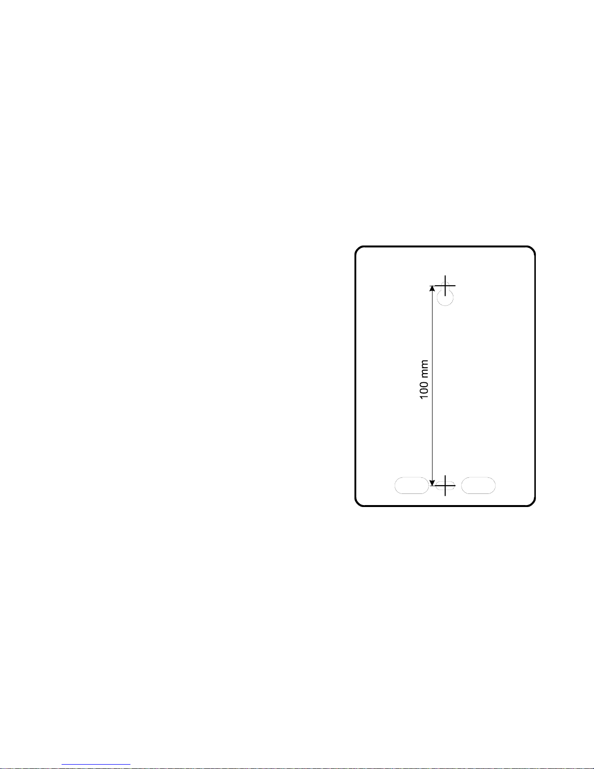
Drilling diagram of TD-101(W)
Page 3

Telephone dialer TD-101 / TD-101W - 3 - MDJ512 10
Conformity:
Hereby, Jablotron Ltd., declares that this TD-101(W) is in compliance with the essential requirements
and other relevant provisions of Directive 1999/5/EC. Original of the conformity assessment can be
found at the web page www.jablotron.cz
, section Technical support.
Notes :
Although this product does not contain any harmful materials we suggest you to return the product to
the dealer or directly to the producer after usage.
1. Description
The TD-101 is an automatic dialing device that transmits prerecorded information via the telephone line.
The dialer can send two different 10 second voice messages (or one 20 second message) to four phone
numbers. It can also send two different Numeric messages to two different PAGERS and four digital codes
to a monitoring station. The desired type of communication is easily selected during installation.
The dialer has two trigger inputs. The optional model TD-101W can also be triggered remotely with a
wireless remote control.
There are three levels of operation for the TD-101: standby, user, and installer. Three light emitting
diodes on the front of the TD-101 show what level the dialer is in.
In standby mode the TD-101 waits for an input from either of the trigger inputs or from the built in keypad.
At the user level (accessible with User Code) you can enter and delete phone numbers, change the
voice messages, change the user code, or test that the TD-101 is functioning properly. Model TD101W can also "learn“ a remote control code in this level.
At the installer level (accessible with Installer Code) you can modify optional functions of the dialer
and enter data for digital communication with a monitoring station.
All data is stored in the TD-101's EEPROM memory. So disconnecting the power from the dialer will not
erase the data. An emergency reset feature can return the dialer to its original factory settings when
necessary.
The autodialer takes priority on your telephone line. When triggered, it will switch all other devices
(phone, fax, PABX) off line. By checking signals on the line (dial, busy or ringing tone) the dialer knows
what its next response should be. A built in speaker can be used as an audible monitor of the dialer
function. The telephone line is electrically separate from the power and trigger inputs. The TD-101 has
specially designed circuits to protect your telephone line from lightning strikes overvoltage. Tamper
protection is also provided.
1.1. Possibilities of use
The TD-101 dialer has a wide spectrum of use:
• property protection - connected with a house alarm system it can send not only an alarm
message, but also arm/disarm information or panic signal
• emergency calls - ill or old people can easily call a doctor or relatives for help using the TD-101.
The dialer can be triggered by pressing the
F key, or by an additional push button wired to the
input. Model TD-101W can also be triggered with a wireless remote control.
• technical information sending - the dialer can automatically report failures of crucial devices
(refrigerator, cooling systems, pumps, heating systems, elevators etc.) or in connection with a
suitable sensor it can inform about reaching of a critical level of controlled parameters
(temperature, humidity, water level etc.).
2. Specifications
operating voltage 12VDC (10-14V)
current consumption stand by 15 mA max.
operating 100 mA max.
trigger inputs IN1 & IN2 separated with optocouplers
option TD-101W also wireless
tamper switch 1A / 60V max.
telephone line electrically separated, over voltage protection
dialing method pulse / tone
phone number Memories voice message 4x 16 digits (Mem1-4)
pager 2x 26 digits (Mem5,6)
monitoring station 2x 16 digits (Mem7,8)
phone line signal detection dialing, busy or ringing tone
voice message duration 2x 10 or 1x 20sec.
monitoring station protocols ADEMCO, SILENT KNIGHT, SESCOA, FRANKLIN, DCI,
VERTEX, RADIONICS, DTMF 1400, DTMF 2300
can be connected to analogue interfaces TBR 21/1998, EG 201 121 V1.13/2000, AS/ACIF S002/2001
(Australia)
Page 4
Telephone dialer TD-101 / TD-101W - 4 - MDJ512 10 Telephone dialer TD-101 / TD-101W - 21 - MDJ512 10
3. TD-101 includes
the dialer, 2.5m telephone cable, set of screws, manual, and
emergency
F button marking label. Model TD-101W, in
addition, includes a wireless remote control (RC-10)
4. Installation
We recommend professional installation of the dialer. The
dialer should be fixed in the desired location using the two
included screws (see drilling diagram at the end of this manual).
First, partially screw in the top screw and slide the screw head
through the hole in the upper part of the TD-101 rear panel. Then
open the dialer terminal compartment cover and mark the position
of the second screw. Place cables through the hole for cables in
the rear panel before installing the second screw. Do not open the
upper part of TD-101 housing during installation; doing so will
result in voiding of warranty.
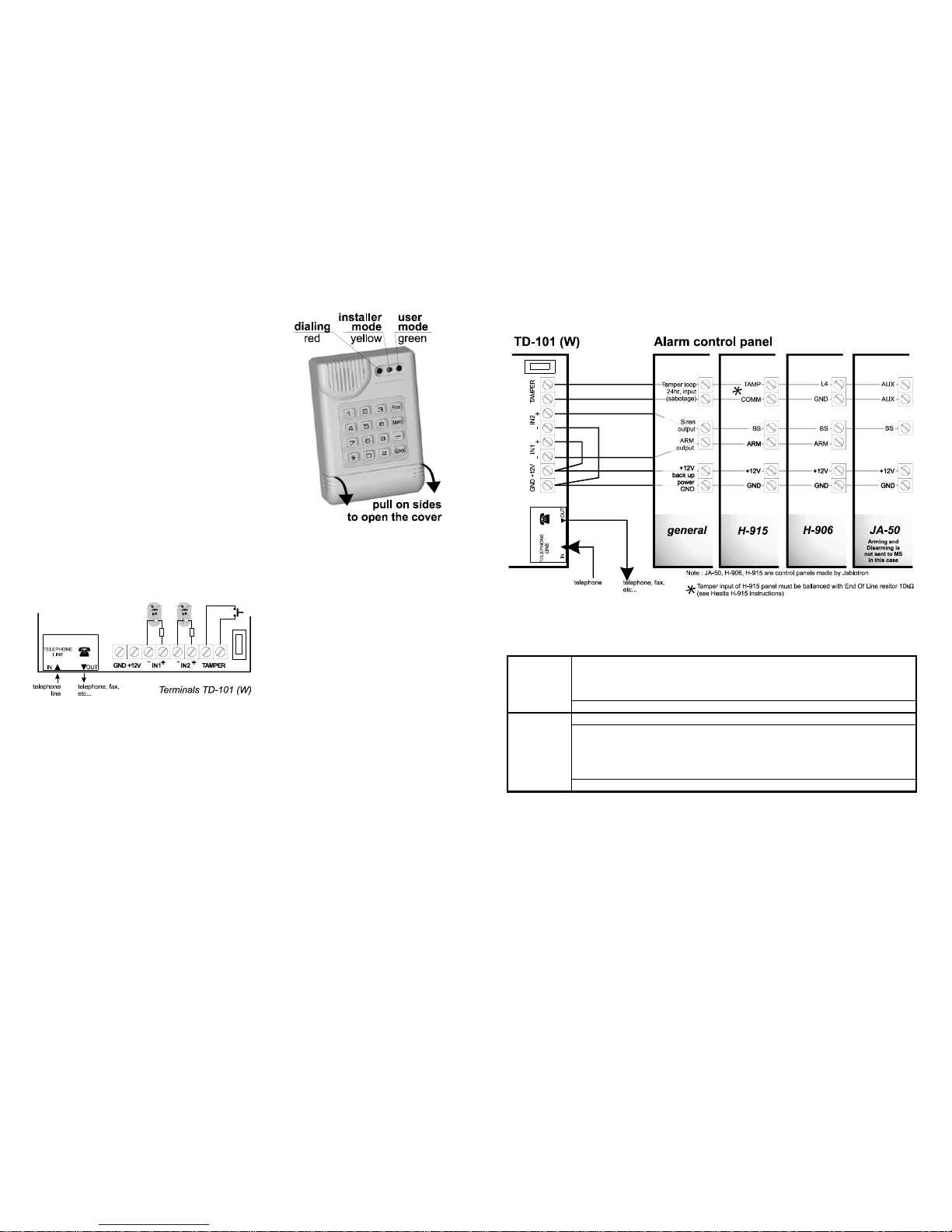
4.1. Terminal Description
IN telephone line input (inlet of the telephone line to
the house)
OUT telephone line output (phone, fax etc.); in the stand by mode the line operates as normal. If
triggered, the TD-101 will use the line (switch off the other devices)
+12V, GND external power supply (12VDC, max. 100mA)
TAMPER tamper switch (normally closed contacts)
IN1 +/- positive and negative poles of the first trigger input
IN2 +/- positive and negative poles of the second trigger input
Both TD-101 trigger inputs have built in optocouplers. The dialer is triggered when an optocoupler current is switched on (factory default),
opposite logic of inputs is programmable (triggering by the current switching off). There are
many possibilities on how to connect the trigger
inputs - see examples on page 20. Consider
that the dialer reacts only to signals with a
duration of 0.1sec. or longer. Each optocoupler
is ON only if its input terminal voltage is 5 to
20V.
5. Operation
When power is supplied, the dialer will perform an automatic self test (red LED turns on for
10 seconds). Then the TD-101 will enter the stand by mode. In this mode, the TD-101 is waiting for an
input form either the keypad or the trigger inputs. For correct function of the dialer, the telephone
numbers and messages must first be programmed (see chapter 6.).
5.1. What does the dialer do if activated:
• seizes the telephone line (switches off all other devices)
• checks dial tone, if the tone is not detected, it will try to release the line again
• dial the first tel. number and if detects:
• ringing tone, it will send the message and will not call this number again
• busy signal, it will call next number and then will try to call the previous number again
The red LED will light when the dialer has been triggered. Once the dialer has been triggered, it's dialing
procedure can be terminated by pressing and holding the
E key (if enabled in installer level). This is
possible only when the IN1 and IN2 inputs are not triggered.
11.3. Example of TD-101(W) use with different alarm systems
Suggestion of programming for the configuration above
tel. number memories
Mem
1, 2 - not used
user mode
3, 4 - numbers for alarm voice message
setting
5 - not used
6 - alarm PAGER number and data
record only voice mess. no. 2
data for Monitoring Station
four report codes disarming
installer
mode
can be programmed arming
setting
(see chapter 8) alarm
end of alarm
logic of IN1 and IN2 inputs Normally Closed contacts
Page 5

Telephone dialer TD-101 / TD-101W - 20 - MDJ512 10 Telephone dialer TD-101 / TD-101W - 5 - MDJ512 10
11. Examples of TD-101(W) use
The dialer inputs are separated with optocouplers, so the variety of possible connections is really
wide. The following examples are only for your reference. Other connections and settings are also
possible to meet your requirements. Ask you distributor if you need any advice regarding the TD-101
installation or programming.
11.1 Trigger inputs IN1 and IN2 connection
The input optocoupler is switched on, if its voltage is from 5 to 20V, minimal trigger signal duration
must be 0.1 sec.
normally open triggering with
contacts triggering switching transistors to GND
(for normally closed contacts
select opposite logic of the IN inputs)
combined triggering one voice message only
ARM = arming of alarm system (20 seconds)
siren = alarm in the system (N.C. or NO. contact
(typical for use with monitoring station) trigger - selectable)
11.2. Use of the dialer only for emergency dialing (old or ill people)
Connect the dialer to the telephone line (between the wall plug and the telephone set). Use an adapter
with output voltage 12VDC, min. 100mA to power the dialer (wire the adapter to +12V and GND terminals,
mind the polarity).
Enter the user mode (see chapter 6.) to program the telephone numbers for the voice message to
memories
Mem3 and Mem4. You can also program a Pager number & data which should be displayed
to memory
Mem6. Then record voice message no. 2 and return to the stand by. Now the dialer is ready for
emergency calls.
It can be triggered with the
Fkey (use an adhesive sticker to make it more visible). Model
TD-101W can also be triggered by remote control. An additional push button (installed by the patient’s
bed for example) can be wired to the dialer input IN2 (see the first diagram above - normally open
contact trigger).
Page 6

Telephone dialer TD-101 / TD-101W - 6 - MDJ512 10 Telephone dialer TD-101 / TD-101W - 19 - MDJ512 10
6. Voice & pager messages setting
Phone numbers, voice messages and Pager numbers & messages can be set in the USER MODE
6.1. How to open USER MODE
Enter User Code (factory setting is 1234) to open the user mode. The user mode is indicated by the
green LED.
All parameters are programmed in the following sequences. If the first key of the sequence is entered,
the red LED will start to flash. When the sequence is completely entered, the red LED will turn off (data will
be stored). A started sequence entering can be terminated by pressing the
E key at any time.
After all programming the user mode must be finished by pressing the
Ekey (all the LEDs will turn
off). The dialer can not be activated in the user level !
6.2. Entering telephone numbers for voice messages sending
Telephone numbers can be entered in the user mode (the green LED is ON - see 6.1.). The dialer
has 4 memories
Mem1 to Mem4 which are for voice messages dialing. Telephone numbers can be
entered including an area code number for long distance calls. The dialer can also be used to call a
mobile phone. To program telephone numbers, enter :
DDDD
... D
M
E
where:
D is a telephone number, keys
to or B i.e. pause. Pause can not be in the first position.
Keys
and can also be programmed in tone dialing mode. Each telephone number can
have up to 16 digits.
E
indicates into which memory (1 to 4) the tel. number will be stored.
When IN1 is triggered, voice message no 1 is sent to Mem1 and Mem2; when IN2 is triggered,
message no. 2 is sent to
Mem3 and Mem4. Remote control button or F key pressing has the same
effect as IN2 triggering. If both inputs, IN1 and IN2, are triggered simultaneously, the dialer will react the
same way as the IN1 is triggered at first and the IN2 after that.
Example: Telephone number 02 311603 will be stored into memory Mem2.
B M
6.3. Voice messages recording
Voice messages can be recorded in the user mode (the green LED is ON - see 6.1.). To record a
message, enter:
M
E
where:
E
is the message number or - press and keep down the number key while speaking in to the
microphone (max. 10 sec). The message will be played back automatically for 40 seconds when
you release the button (can be stopped with
Ekey). The voice messages can also be played in
stand by mode, after entering
M
for the first and M for the second message.
Note: If only one message (20 sec.) is selected in the installer level, record it as message no.1.
Page 7

Telephone dialer TD-101 / TD-101W - 18 - MDJ512 10 Telephone dialer TD-101 / TD-101W - 7 - MDJ512 10
6.4. Entering telephone numbers and data for PAGER
Telephone numbers and data can be entered in the user mode (the green LED is ON - see 6.1.),
entering:
DDDD
... D
M
E
where:
D
can be to or B i.e. pause. Pause can not be used as a first digit. You can enter a
maximum of 26 digits. If the
Fkey is entered, it will make a long pause and will switch for
tone dialing if pulse dialing is selected (so
Fkey should be used as a message code
separator),
and can also be dialed if tone dialing method is selected
E
is the tel. number memory or (with IN1 triggering, the number Mem5 will be dialed,
with IN2 triggering the number
Mem6 will be dialed). Remote control button or Fkey
pressing has the same effect as IN2 triggering. If both inputs IN1 and IN2 are triggered
simultaneously, the dialer will call the first pager according to
Mem5 and then the second
pager according to
Mem6.
Example:
F „Pager number“„message“
M E
Format of the pager number and data can be different, check details with your PAGING provider.
6.5. Deleting telephone numbers
Telephone numbers for voice & pager messages can be deleted in user mode (the green LED is ON
- see 6.1.), entering:
B ME
where:
E
is the memory number 1 to 6 which will be erased. If a number is erased, the corresponding
dialing will not be performed
Example: Deleting of telephone number from memory Mem3 :
B
M
6.6. Remote control code learning (only for model TD-101W)
A new remote control can be taught to the dialer in the user mode (the green LED is ON - see 6.1.),
entering:
M
After entering M the dialer is in the remote control learning mode. Activate all the remote
controls (max. 3) one by one. Learning of the remote control is confirmed with a beep. Close the
learning mode by pressing the
Ekey (learning of the third remote control will close it automatically).
Closing is confirmed with two beeps. Both buttons of the remote control have the same function.
Note: when the first remote control is taught in the learning mode, all previous remote controls are
forgotten.
6.7. Erasing of remote controls (only for model TD-101W)
All remote controls can be erased from the TD-101W memory in the user mode (the green LED is
ON - see 6.1.), entering:
M
B
Note: This instruction can be used if you lost your remote control.
Page 8

Telephone dialer TD-101 / TD-101W - 8 - MDJ512 10 Telephone dialer TD-101 / TD-101W - 17 - MDJ512 10
6.8. Testing the message sending
Sending of voice & Pager messages can be tested in the user mode (the green LED is ON - see
6.1.), entering:
FM
E
where:
E
is the tel. number memory 1 to 6 in which the corresponding message will be sent. If you
enter 0 all tel. numbers will be tested. Testing is always audible (you can hear tel. line
signals and voice messages from the built in speaker).
Example : Voice message no. 1 will be sent to tel. number Mem2 :
FM
6.9. Changing of the User Code
To avoid non authorized access to the user mode, change the User Code for a new one. The code
can be changed in the user mode (the green LED is ON - see 6.1.), entering:
M
DDDDDDDD
where :
DDDD
is your new user code (four digits). The new code must be entered twice to be changed
(protection of accidental change). Original factory default setting of the User Code is 1234.
Example : The user code will be changed for code 2010 :
M
Page 9

Telephone dialer TD-101 / TD-101W - 16 - MDJ512 10 Telephone dialer TD-101 / TD-101W - 9 - MDJ512 10
9. Trouble shooting
• It is impossible to stop the dialing function with the Ekey even if it is enabled in the
installer mode. Check if either trigger input IN1 nor IN2 is active (especially if you changed the
trigger input logic to a normally closed contact). Additionally, remember that communication with
the monitoring station can not be stopped until it is finished.
• Reaction of the dialer is opposite to what you expect - no reaction when trigger inputs are
activated and the dialer starts to work after inputs are deactivated. In this case the trigger input
logic incorrectly (see item 8.4.).
• Dialer does not work when you press the emergency key
F- check that voice message no.
2 was recorded and that there is a telephone number stored in memory
Mem3 or Mem4.
Remember that the emergency function of the
F key can be disabled in the installer mode (see
item 8.11.).
• Dialer does not work after any kind of triggering - check that it is not in the user or installer
mode (green and yellow LEDs must be off). Press the
Ekey to get back to the stand by mode.
Check if the TD-101 is powered correctly (press the
Ekey and you should hear a beep). Check
also, if the voice messages are recorded and that the telephone numbers are stored in
corresponding memories (see chapter 6).
• It is impossible to enter the user or installer mode - it can be entered only if the dialer is not
dialing (red LED must be off). Wait until the dialing is finished or try to stop the dialing with the
Ekey (if stop has been enabled in the installer level).
• You need to temporarily switch the dialer off - for example if the device that controls the dialer
triggers is malfunctioning. In such a case enter the user mode with your user code (the green LED
will be switched on), the TD-101 will be disabled. Remember that the user mode can only be
entered in the moment when the dialer is not calling (red LED must be off). Do not forget to switch
the dialer back to stand by (pressing its
Ekey), after the malfunction is repaired
9.1. Emergency reset
In the event, that you forget your user or installer code (or for some other reason), it is possible to
completely reset all parameters of the TD-101. To do this:
• disconnect the power and wait 1 minute
• reconnect the power (red LED turns on) enter
B
(within
10 seconds after the power is reconnected)
This procedure resets the factory default settings (UC=1234, IC=1010), all phone numbers and remote
controls (TD-101W only) will be deleted. All the optional functions and parameters will be set to the
factory default setting (see table on page 18 for details).
Page 10

Telephone dialer TD-101 / TD-101W - 10 - MDJ512 10 Telephone dialer TD-101 / TD-101W - 15 - MDJ512 10
7. Monitoring station data sending
Function of the TD-101 including the Monitoring Station (MS) communication is demonstrated in the
diagram on page 9. Data is sent to the monitoring station before voice & Pager messages are sent (if
these messages are used). All parameters of the MS communication should be programmed in
cooperation with your monitoring service provider. Programming of the data for the MS is only possible
in the Installer mode.
If you do not use the dialer to send data to a monitoring station, do not program anything in this
section.
7.1. Opening of Installer Mode for monitoring station data programming
To enter Installer level from Standby, enter Installer code IC press B and enter Installer Code
IC again. Factory default IC is 1010 so when you open the Installer mode for the first time, enter
B
. The installer level is indicated by the yellow LED.
All parameters are programmed in the following sequences. If the first key of the sequence is
entered, the red LED will start to flash. When the sequence is completely entered, the red LED will
turn off (data will be stored). A started sequence entering can also be terminated by pressing the
Ekey at any time.
After all programming is finished, the Installer mode must be exited by pressing the
Ekey (all the
LEDs will turn off). The dialer can not be activated in the Installer level !
7.2. Entering telephone numbers of the Monitoring Station
Telephone numbers can be programmed in the Installer mode (the yellow LED is ON - see 7.1.),
entering:
DDDD
... D
M
E
where:
D
is a telephone number, keys to or B (i.e. pause). Pause can not be on the first
position, keys
and can also be programmed in tone dialing mode. Each telephone
number can have up to 16 digits.
E
is the tel. number memory 7 = main tel. number (Mem7), 8 = alternate tel. number (Mem8).
The alternate number is only called if the main number is busy.
Example: The main telephone number of the monitoring station will be 811 777 :
M
7.3. Deleting of Monitoring Station telephone numbers
Telephone numbers for MS can be deleted in the installer mode (the yellow LED is ON - see 7.1.),
entering:
B M%
where:
%
is the memory number 7 or 8 which will be erased. If a number is erased, the corresponding
dialing will not be performed.
Note: If both numbers for MS are erased, there will be no communication to the monitoring
station
Example: Spare MS telephone number will be erased :
B M
If Stop with
Ekey is enabled, the TD-101 action can be stopped only if no input is triggered. The dialer
action is terminated a few seconds after the
Ekey is pressed.
If Stop is disabled, the communication can not be stopped before its end.
Example: The STOP will be disabled :
F
8.11. Emergency triggering with Fkey
Emergency trigger key can be enabled or disabled in the installer mode (the yellow LED is ON - see
8.1.), entering:
F
D
where:
D
=0 emergency trigger disabled
D
=1 emergency trigger enabled (factory default setting)
If you use the
Fkey as an emergency button, you can mark the key with an adhesive label which
is included.
Note: The above setting does not have any effect to the remote control trigger of TD-101W model.
Example: Emergency trigger will be disabled :
F
8.12. Changing of the Installer Code
To avoid non authorized access to the installer mode, change the Installer Code for a new one. The
code can be changed in the installer mode (the yellow LED is ON - see 8.1.), entering:
M
DDDDDDDD
where :
DDDD
is the new installer code (four digits). The new code must be entered twice to be changed
(protection of accidental change). The original factory default setting of the Installer Code is
1010.
Example : The user code will be changed for code 3112 :
M
8.13. Duration of Pause in Pager dialing
Duration of the pause which is generated with the Fkey in pager number programming can be
selected in the installer mode (the yellow LED is ON - see 8.1.) entering.
F F
D
where :
D
=0 pause = 5 seconds (factory default)
D
=1 pause = 10 seconds
Example: 10 seconds Pause will be selected:
F F
Page 11

Telephone dialer TD-101 / TD-101W - 14 - MDJ512 10 Telephone dialer TD-101 / TD-101W - 11 - MDJ512 10
8.7. Number of attempts to call monitoring station
Number of attempts to call MS can be programmed in the installer mode (the yellow LED is ON - see
8.1.), entering:
F
D
D
is a number of attempts to call monitoring station, can be from 1 to 8. A successful
communication handshake cancels all following attempts.
(factory default setting are 3 attempts)
Example: Five cycles will be selected :
F
8.8. Telephone line signals detection
Detection of signals can be enabled or disabled in the installer mode (the yellow LED is ON - see
8.1.), entering:
F
D
where:
D
=0 detection disabled
D
=1 detection enabled (factory default setting)
If the telephone line signals detection is enabled, the dialer will check for the dial tone at first. If a
dial tone is not present, it will try to release the line again. Then it will dial the first stored number and if
it gets a ringing tone, it will send the message once and it will not call this number again.
If the number is busy, it will dial the next number and the dialing will be repeated after that.
If the signals detection is disabled, the dialer will make as many cycles as programmed in
F
, no
matter what the signals on the line are.
Example: Detection will be disabled :
F
8.9. Audible function monitor (built in speaker)
The built in speaker can be enabled or disabled to listen the dialing and calling. It can be selected in
the installer mode (the yellow LED is ON - see 8.1.), entering:
F
D
where:
D
=0, disabled
D
=1, enabled (factory default setting)
The audible line monitoring with built in speaker is always enabled when you test the TD-101.
Example: The audible dialing monitor will be enabled :
F
8.10. Stop function with Ekey
Stop function is selectable in the installer mode (the yellow LED is ON - see 8.1.), entering:
F
D
where:
D
=0 stop is disabled
D
=1 stop is enabled (factory default setting)
7.4. Monitoring station Communication Protocol & Format setting
Protocol and format can be selected in the Installer mode (the yellow LED is ON - see 7.1.), entering:
M
DE
where:
D
means protocol and E means format, see the following table:
D
protocol
E
format
0 ADEMCO / SILENT KNIGHT SLOW 10 BPS 0 3/1 not extended
1 SESCOA, FRANKLIN, DCI, VERTEX 20 BPS 1 3/2
2 SILENT KNIGHT FAST 20 BPS 2 4/1
3 RADIONICS (2300) 3 4/2
4 RADIONICS (1400) 4 3/1 extended
8 DTMF 1400
9 DTMF 2300
Example: SILENT KNIGHT FAST 20 BPS protocol and 4/1 format will be selected
M
7.5. Account number programming
Account number code can be entered in Installer mode (the yellow LED is ON - see 7.1.), entering:
M
EEEE
where :
EEEE
is the account number. If format 3/1 or 3/2 is selected (see 7.4. above) the first digit will
not be sent.
Transmitted codes are usually „HEX“ data, i.e. each digit can be 0 to 15 (F). To enter HEX data,
use
key. Enter number 10(A) as , 11(B)=, 12(C)=, 13(D)=, 14(E)=,
15(F)=
. Number 0 in account number must be entered as
.
Example: Account number 12A5 will be stored :
M
7.6. Reporting codes programming
Reporting codes for activation and deactivation of the dialer inputs can be programmed in the
installer mode (the yellow LED is ON - see 7.1.), entering:
M
D EE
where:
D
means event on the inputs, see following table:
input activation deactivation
IN1 3 4
IN2 5 6
%E
is the report code for MS, (if %E = 00 is selected, this event will not be reported)
Transmitted codes are usually „HEX“ data, i.e. each digit can be 0 to 15 (F). To enter HEX data, use
key. Enter number 10(A) as
, 11(B)=, 12(C)=, 13(D)=, 14(E)=, 15(F)=
.
Example: Code 3D will be reported if IN2 input is triggered :
M
Page 12

Telephone dialer TD-101 / TD-101W - 12 - MDJ512 10 Telephone dialer TD-101 / TD-101W - 13 - MDJ512 10
7.7. Testing the Monitoring Station communication
Communication to the MS can be tested in the installer mode (the yellow LED is ON - see 7.1.), entering:
FM
D E
where:
D
is the tel. number memory 7 or 8 which will be called
E
means event number (3, 4, 5 or 6) which code will be sent (see item 7.6.)
Example: Report code corresponding to IN2 input triggering (activation) will be sent to the main tel. number :
FM
8. Optional functions and parameters programming
The settings chosen in the Installer mode can significantly customize the dialer operation. This
programming should be done by a professional installer.
8.1. Opening of Installer Mode for Optional functions programming
To enter Installer level from the Standby, enter Installer code IC press B and enter Installer
Code IC again. Factory default IC is 1010 so when you open the Installer mode for the first time,
enter
B
. The installer level is indicated by the yellow LED.
All parameters are programmed in the sequences started with
Fkey. If a sequence is entered,
the red LED will start to flash. When the sequence is completely entered, the red LED will turn off
(data will be stored). A started sequence entering can also be terminated by pressing the
Ekey
at any time.
After all programming, the Installer mode must be exited by pressing the
Ekey (all the LEDs will turn
off). The dialer can not be activated in the Installer level !
Note: The installer code IC can also be used to open the user level, the same way as the User Code.
8.2. Dialing method
Pulse or tone dialing can be selected in the Installer mode (the yellow LED is ON - see 8.1.),
entering:
F
D
where:
D
= 0 pulse
D
= 1 tone (factory default)
The dialing method can also be changed from pulse to tone by entering Finside the phone number (it
will insert a pause and it will switch to tone dialing); the
Fkey can not be stored as the first digit.
Example: tone dialing will be selected
F
8.3. Number of voice messages
One or two voice messages can be selected in the installer mode (the yellow LED is ON - see 8.1.),
entering:
F
D
where:
D means number of messages 1 = 1x 20sec. or 2 = 2x 10sec.
(factory default = 2 messages, max. 10sec. each)
If only one message is selected (max. 20sec.) :
• it should be recorded as message no. 1
• IN1 triggering will send the message to
Mem1 and Mem2
• IN2 triggering will send the message to
Mem3 and Mem4
• simultaneous triggering of IN1 and IN2 will send the message to all
Mem1 to Mem4 tel. numbers
• Pager and monitoring station communications will not be effected
• to play the message in stand by press only the
Mkey
Example: Only one voice message, max. 20sec. will be selected :
F
8.4. Trigger inputs IN1 and IN2 logic
The method of IN1 and IN2 triggering can be selected in the installer mode (the yellow LED is ON -
see 8.1.), entering:
F
D
where:
D
= 0 inputs are triggered if the input optocoupler current is switched off (N.C. trigger)
D
= 1 input is triggered if the input optocoupler current is switched on (N.O. trigger)
(factory default setting is 1 = N.O. trigger)
Example: IN1 and IN2 will react to switching the current off (suitable for Normally Closed contacts)
F
8.5. Trigger delay
The dialer reaction delay can be programmed in the Installer mode (the yellow LED is ON - see 8.1.),
entering:
F
D
Dcan be from 0 to 9, it means that the duration of the delay x10sec (i.e. 0 to 90sec.). Dialing
will start with the delay only if the corresponding Input is triggered longer than the selected
delay. If the input is deactivated before the delay time elapses, the dialer will not work. The delay
is valid for all voice, Pager and Monitoring Station dialing.
Note: triggering with
Fkey or with the remote control (TD-101W) will always have no delay.
(factory default setting is no delay = instant reaction)
Example: Delay 30sec. will be selected :
F
8.6. Number of cycles to send voice & Pager messages
Number of attempts to call each number can be selected in the installer mode (the yellow LED is ON
- see 8.1.), entering:
F
D
Dmeans number of cycles, can be 1, 2 or 3. One cycle means sending of the corresponding
messages to all stored phone numbers in the
Mem1 to Mem6 memories
(factory default setting are 3 cycles)
Example: Two cycles will be selected :
F
 Loading...