

Page 1
Detektor požáru SD-280
Výrobek slouží k detekci požárního nebezpečí v interiéru obytných nebo
obchodních budov. Není určen k instalaci do průmyslového prostředí.
Pro lokální varování má zabudovanou varovnou sirénu a červenou signálku.
Napájí se z externích zálohovaných napájecích zdrojů typu A nebo B dle
ČSN EN 50131-6 nebo ústředen poplachových zabezpečovacích systémů.
Pro tyto ústředny poskytuje elektronické relé výstup poplachového signálu
svorkami OUT, informace o odejmutí detektoru z úchytu je k dispozici přes
svorky TMP (bezpotenciálový rozpínací kontakt).
SD-280 obsahuje dva samostatné detektory – optický detektor kouře a
teplotní detektor. Optický detektor kouře pracuje na principu rozptýleného
světla a je velmi citlivý na větší částice, které jsou v hustých dýmech, méně
citlivý je na malé částice vznikající hořením kapalin, jako je například alkohol.
Proto je vestavěn i detektor teplot, který má sice pomalejší reakci, ale na
požár vyvíjející rychle teplo s malým množstvím kouře tento detektor teplot
reaguje podstatně lépe. Mikroprocesor provádí digitální analýzu těchto
veličin, což výrazně zvyšuje odolnost vůči falešným poplachům.
Pokrytí prostoru a umístění detektoru
Kouř se přenáší do detektoru prouděním - musí být proto namontován tak,
aby kouř do detektoru proudil například po stropě. Je vhodný do většiny
objektů, ale nevhodný do volného prostoru nebo venkovního prostředí. Není
vhodný také tam, kde se kouř může před detekcí rozptýlit na velkou plochu,
zvlášť pod vysokými stropy – kouř pak nedosáhne k detektoru.
Pro montáž detektoru je rozhodující výška stropu. Od bodu, kde je
namontován, je schopen pokrýt kruhovou plochu o poloměru dle tabulky:
detekce
kouře
detekce
teploty
< 4,5
4,5÷6 6÷8 8÷11 11÷25
7,5* m 7,5* m 7,5* m 7,5* m
5* m 5* m 5* m
výška stropu (m)
> 25
nevhodné nelze
nevhodné nelze nelze
nelze – v uvedeném rozsahu výšek nelze použít
nevhodné – běžně se v uvedených výškách nepoužívá
* – jedná se o poloměr plochy pod detektorem
• Umístění pod rovnými stropy
Z důvodu možné existence chladné vrstvy u stropu nesmí být detektory
zapuštěny do stropu. Vodorovná vzdálenost z jakéhokoliv místa v
chráněném prostoru k nejbližšímu SD-280 nesmí přesáhnout provozní
poloměr uvedený v tabulce.
• Umístění pod šikmými stropy
Pro SD-280 montované ve hřebenu šikmých stropů mohou být poloměry
uvedené v tabulce zvětšeny o 1 % na každý jeden stupeň sklonu stropu až do
maximálního zvětšení o 25 %. Pokud má chráněný prostor pilovitou
střechu, potom by měly být SD-280 namontovány v každém hřebenu.
Pokud je výškový rozdíl mezi horní a spodní částí hřebenu menší než 5 %
výšky hřebenu nad podlahou, potom může být střecha považována za plochou.
• Stěny, přepážky, zátarasy, příhradové stropy
SD-280 nesmí být montovány blíže jak 0,5 m od jakýchkoliv zdí nebo
přepážek. Pokud je místnost užší než 1,2 m, potom musí být detektory
montovány uvnitř střední třetiny šířky. V případě, že jsou místnosti rozděleny
na sekce pomocí zdí, přepážek nebo skladovacích regálů dosahujících do
0,3 m od stropu, na přepážky se pohlíží stejně, jako kdyby dosahovaly až
ke stropu, a sekce se považují za samostatné místnosti. Ve všech
směrech pod detektorem se musí udržovat volný prostor alespoň 0,5 m.
Stropy, které mají nepravidelnosti o rozměrech menších než 5% výšky
stropu, mohou být považovány za ploché a použijí se hranice poloměrů
z tabulky. Jakékoliv nepravidelnosti stropu (jako je nosník), které mají
rozměry větší než 5 % výšky stropu, jsou považovány za stěnu a platí
vše výše uvedené.
• Ventilace a pohyb vzduchu
Detektory nesmí být namontovány přímo u přívodu čerstvého vzduchu
například z klimatizace. Je-li vzduch přiváděn perforovaným stropem, nesmí
strop být perforován na poloměru alespoň 0,6 m okolo každého detektoru.
• Detektor tedy neumísťujte:
• tam, kde špatně proudí vzduch (výklenky, rohy, vrcholy střech tvaru A apod.)
• tam, kde se práší, kouří cigarety nebo se vyskytuje pára
• v místech, kde intenzivně proudí vzduch (blízkost větráků, tepelných
zdrojů, vyústění vzduchotechniky, průduchů apod.)
• v kuchyních a na místech, kde se vaří (pára, kouř a mastné výpary
mohou způsobit poruchy detekce).
Upozornění: Nejčastější příčinou nežádoucí aktivace
bývá nevhodné umístění detektoru.
Podrobnější pokyny k instalaci jsou uvedeny v ČSN TS 54-14.
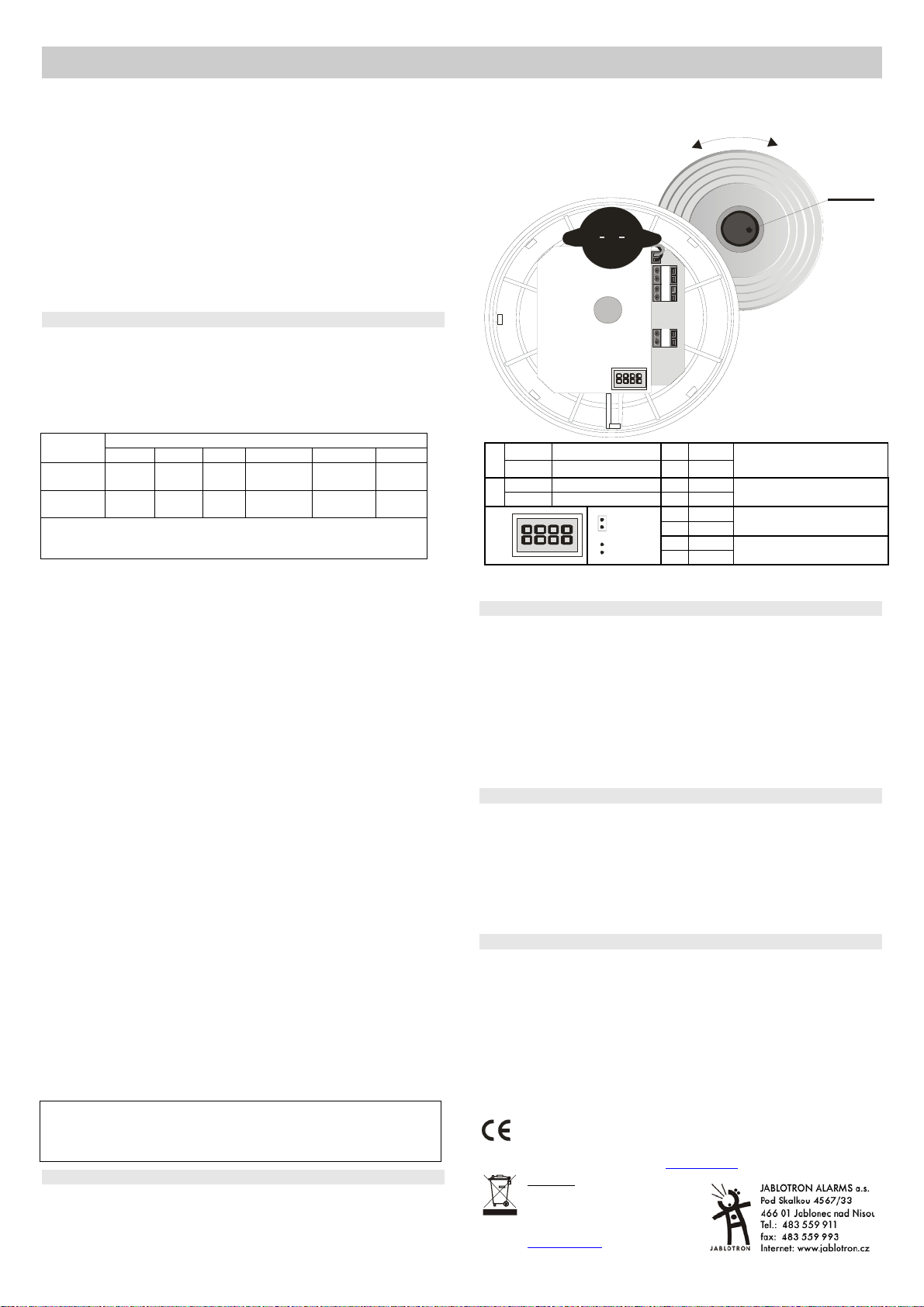
Instalace detektoru
1. otevřete detektor pootočením krytu doleva
2. přišroubujte zadní plast na vybrané místo
3. připojte svorky OUT a TMP - před zapojením vodičů do svorkovnice
detektoru si nejprve prostudujte instalační manuál ústředny
4. nastavte požadované funkce detektoru - viz tabulka níže
Detektor požáru SD-280 1 / 2 MLE51000
5. připojte napájení do svorek 12V
6. detektor potřebuje cca 20 sekund ke stabilizaci kdy svítí signálka.
Následně se provede test jehož úspěšnost je potvrzena pípnutím.
u
t
í
ř
v
e
t
o
z
a
v
ř
í
t
TEST
TMP ALARM
+ 12V -
1
NO spínací kontakt
ON
1
2
OFF
ON
OFF
NC rozp. kontakt
paměť zapnuta
paměť vypnuta
ON
1
12 34
OFF
Při změně nastavení se automaticky do 10 sec. provede test detektoru a
poté se uloží nové nastavení
Požární poplach
Optický detektor: Po vniknutí kouře do detektoru během analýzy jako
předpoplach blikají LED. Pokud zakouření trvá, je spuštěn akustický poplach,
který začíná s nízkou intenzitou, poté přechází na plný výkon.
Teplotní detektor: Signalizace probíhá shodně s optickým detektorem.
Paměť poplachu: Zapíná a vypíná se pomocí DIPu 2 dle tabulky. V případě
zapnuté paměti události při poplachu signálka indikuje aktivaci detektoru i po
vyvětrání. Indikaci lze ukončit stiskem tlačítka.
Umlčení sirénky při poplachu: Po celou dobu požárního nebezpečí
detektor blikne vždy 2x krátce a současně houká (vyšší hlasitostí než při
testu). Při poplachu lze sirénku umlčet stisknutím testovacího tlačítka na cca
3sec. Pokud nedojde k vyvětrání kouře nebo poklesu teploty, akustická
signalizace je po cca 10 minutách znovu aktivována.
Testování detektoru
Test se provádí automaticky po připojení napájení nebo při změně nastavení
pinové lišty. Funkci detektoru lze ověřit stisknutím a podržením testovacího
tlačítka na cca 3 s. Pokud detektor jednou pípne a krátce zasvítí signálkou, je
v pořádku. Přitom dojde k sepnutí / rozepnutí výstupu (viz tabulka).
Tento test by měl být proveden nejméně 1x za 30 dní. V případě poruchy pípne
4x a trvale bliká. V takovém případě odpojte napájení na 1 minutu a pak ho znovu
zapojte. Pokud se cca po 1 minutě signálka opět rozbliká, předejte detektor do servisu.
Pozor: detektor nikdy netestujte rozděláváním ohně v objektu. Pro
testování kouřem se prodávají simulační testovací spreje.
Technické parametry
napájení 9 – 15 V DC / 2,5 mA (100mA při poplachu)
(zdroj typu A nebo B dle ČSN EN 50131-6)
výstupy - poplachový - OUT 60 V/ 100 mA max.
- sabotážní (poruchový) TMP R = 68 Ω (ochrana
detekce kouře optický rozptyl světla
citlivost detektoru kouře m = 0,11
detekce teplot třída A2 dle ČSN EN 54-5
poplachová teplota +60 °C až + 70 °C
akustický výkon zabudované sirénky min. 85dB / 3 m
rozsah pracovních teplot -10 až +70 °C
rozměry průměr 126 mm, výška 65 mm
splňuje požadavky ČSN EN 14 604, A2 ČSN EN 54-5, ČSN EN 50130-4, ČSN EN 55022
1293-CPD-0095
Poznámka: Výrobek, ačkoliv
neobsahuje žádné škodlivé materiály,
nevyhazujte do odpadků, ale předejte
na sběrné místo elektronického
odpadu. Podrobnější informace na
www.jablotron.cz
Detektor je navržen a vyroben ve shodě s na něj se
vztahujícími ustanoveními: Nařízení vlády č. 616/2006Sb.,
190/2002Sb., je-li použit dle jeho určení. Originál prohlášení
o shodě je na www.jablotron.cz
sekce Poradenství.
3 OFF
4 OFF
3 ON
4 OFF
3 OFF
4 ON
3 ON
4 ON
kouř (ČSN EN 14064) nebo
teplota (ČSN EN 54-5)
pouze kouř (ČSN EN 14604)
(ne teplota)
pouze teplota (ČSN EN 54-5)
(ne kouř)
Kouř a zároveň teplota (obě
podmínky současně)
÷
0,13 dB/m dle ČSN EN 14 604
v sekci Poradenství.
Page 2
The SD-280 fire detector
This device is designed to detect the presence of fire inside residential or commercial
buildings. It should not be installed in industrial premises.
The detector has a built-in local warning siren combined with a red LED indicator. It
is powered by Type A or B external uninterruptible power sources in
conformity with EN 50131-6, or a security alarm system control panel.
The alarm signal output for these control panels is provided by an electronic
relay via the OUT terminals. A signal concerning detector removal from the
holder is available via the TMP terminals.
The SD-280 detector combines an optical smoke sensor with a heat sensor. Both
sensors have their outgoing signals processed digitally, resulting in higher false
alarm immunity. The optical sensor works using a light diffusion principle and is very
sensitive to the presence of large-sized particles which are characteristic of dense
smokes. By contrast, the sensor is less sensitive to small-sized particles which are
typical of cleanly burning fires. In particular, the smoke sensor is not capable of
detecting the by-products of cleanly-burning fluids such as alcohols, for instance.
This deficiency is compensated for by the built-in heat sensor. This sensor provides
a slower reaction when compared to the smoke sensor, but is much better at
reacting to fires with rapidly rising heat producing only a little smoke.
Detection range, detector positioning
Exposing fire conditions to the smoke and heat sensors requires some level of air
circulation. It is therefore necessary to install the detector in such a place on the
ceiling that (in the case of fire) smoke masses are forced to go in the direction of the
detector’s position. This can usually be achieved in most buildings. However, the
detector is not suitable for installation in outdoor spaces or interiors with an extremely
high ceiling where fire by-products would not reach the detector position.
The following table shows the detector’s working range in relation to the height of
the ceiling on which the detector is installed. The range is expressed as the radius of
the circular fire detection area for a detector installed on a ceiling directly above:
Smoke
detection
Heat
detection
< 4,5
7,5* m 7,5* m 7,5* m 7,5* m
5* m 5* m 5* m
4,5÷6 6÷8 8÷11 11÷25
Not applicable – meant for a particular ceiling height range
Not suitable –not usually used in such cases
* – the radius of the detection area below the detector
• Installation on a horizontal level ceiling
Due to the possible occurrence of a cold air layer right under the ceiling, the
detectors must not be imbedded into the ceiling. The distance between any
point to be protected and an imaginary vertical line from the nearest SD-280
detector down to the floor must not exceed the radius indicated in the table.
• Installation on a sloping ceiling
If the SD-280 is installed just under an apex formed by the joining of two
sloping ceilings the values indicated in the table can be increased by 1% for
every degree of slope up to a maximum of 25%. If the space to be protected
is under a saw-tooth type of roof, SD-280 detectors should be installed
under each apex. However, a roof with a shallow saw-tooth form can be
acceptable if the height difference between the highest and lowest parts of
the ceiling does not exceed 5% of the total ceiling height
• Walls, partitions, obstacles, and trussed ceilings
The SD-280 must not be installed closer than 0.5 m from any wall or
partition. A narrow room with a width of less than 1.2m requires the
detector(s) to be placed at a distance of at least one third of the room’s width
away. In the case of separating walls (partitions, warehouse objects) which
do not reach the ceiling, the space is considered to be fully separated if
the gap between the top of the separating wall and the ceiling does not
exceed 0.3 m. A free space of at least 0.5m is required under the detector.
Irregularities in ceiling shape which do not exceed 5% of ceiling height are
considered insignificant – the ceiling can be regarded as being even and
limits from the table are applicable. However, any irregularity (including
beams) exceeding 5% of the ceiling height is considered to be a wall
with the consequences stated above.
• Ventilation and air circulation
The detectors must not be installed directly by a fresh air inlet, e.g. air
conditioning vents. In the case of air being supplied through a perforated ceiling, each
detector must be placed so that no perforation hole occurs within 0.6m of the detector.
• Avoid installing the detector in the following locations:
• Places with poor air circulation (niches, corners, apexes of A-shaped roofs).
• Places exposed to dust, cigarette smoke or steam.
• Places with over-intense air circulation (close to ventilators, heat sources or air
conditioning outlets).
• Kitchens and other cooking places (because steam, smoke or oily fumes can
reduce detector sensitivity).
Caution: The most common reason for the detector to be
accidentally triggered is improper detector location.
See CEN/TS 54-14 standards for detailed installation guidelines.
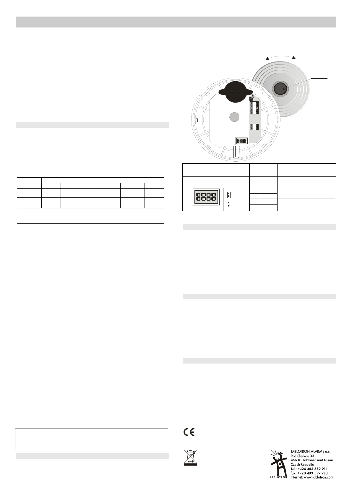
Installation
1. Open the detector by turning the rear cover to the left
2. Screw the rear cover onto the desired location
3. connect the OUT and TMP terminals – consult the control panel manual
before connecting wires to the detector terminal board
Ceiling height (m)
Not suitable
Not suitable
Not
applicable
> 25
Not
applicable
Not
applicable
4. Set the required function via the jumpers – see the table below
5. Connect the power supply to the 12V terminals – regardless of polarity
6. After installing the detector, allow approx. 20 seconds for stabilisation. This
period is indicated by the LED being continuously lit and is followed by an auto-
test. Successful performance of the auto-test is confirmed acoustically
C
n
e
p
O
l
o
s
e
TEST
TMP ALARM
+ 12V -
1
NO closing contact
ON
1
2
1
Testing the detector is automatically performed up to 10 secs after
battery insertion. New settings are saved directly afterwards.
OFF
ON
OFF
12 34
NC break contact
Memory ON
Memory OFF
ON
OFF
3 OFF
4 OFF
3 ON
4 OFF
3 OFF
4 ON
3 ON
4 ON
Smoke (EN 14064) or heat
(EN 54-5)
Only smoke (EN 14604) (heat
indifferent)
Only heat (EN 54-5) (smoke
indifferent)
Smoke and heat (both
simultaneously)
Fire alarm
Optical smoke sensor: Smoke entry into the detector is indicated as a pre-alarm
state by the LED flashing. If the smoke threshold density is exceeded, a siren sound
is generated, gradually increasing in volume.
Heat sensor: indication logic is equal to that of the smoke sensor.
Alarm memory: It is switched ON/OFF via DIP 2 as shown in the table. If the event
memory is armed at the time of alarm, alarm LED indication continues even if normal
conditions are restored. The indication can be stopped by pressing the button.
Silencing the siren during an alarm: During a fire alarm, the detector LED flashes 2
times briefly and the built-in siren sounds (at a higher intensity than during a test). Under
these conditions the siren can be silenced by pressing the test button for approx. 3sec.
However, if normal conditions are not restored within approx. 10 minutes (the smoke
does not clear from the room or the temperature does not drop), the siren re-activates.
Testing the detector
Testing the detector is automatically performed up to 10 secs after
battery insertion or after changing the settings on the jumpers. The
functioning of the detector can be tested by pressing and holding the test button for
approx. 3 seconds. A properly functioning detector responds with one beep and a
short flash. The output is concurrently switched ON / OFF (see the table)
A fault is indicated by 4 beeps and the LED permanently flashing. In this case,
remove the battery and re-insert it after 1 minute. If the fault indication occurs again (the
LED starts permanently flashing after about 1 minute), consult the installer company.
The detector should be tested this way at least once in every 30 days.
Warning: Never start a fire in a building to test the detector. Instead, use smoke-
simulating aerosols for realistic testing.
Specification
Voltage 9 – 15 V DC / 2,5 mA (100mA during alarm)
(Type A or B source pursuant to EN 50131-6)
Outputs - alarm - OUT 60 V/ 100 mA max.
- sabotage (failure) TMP R = 68 Ω (protection)
Smoke detection optical, light dispersion
Smoke sensor sensitivity m = 0.11 - 0.13 dB/m pursuant to EN 14 604
Temperature detection A2 c lass pursu ant to EN 54-5
Fire-alarm temperature +60 °C to + 70 °C
Acoustic power of the built-in siren min. 85dB / 3 m
Operational temperature range -10 to +70 °C
Dimensions diameter 126 mm, height 65 mm
Com plies wit h EN 14 604, A2 EN 54-5, EN 50130-4, EN 55022
1293-CPD-0095
Note: Dispose of batteries safely depending
on battery type and local regulations.
Although this product does not contain any
harmful materials we suggest you return the
product to the dealer or directly to the
manufacturer after use.
JABLOTRON ALARMS a.s. hereby declares that the SD-280 is in
compliance with the essential requirements and other relevant
provisions of Directive 1999/5/EC. The original of the conformity
assessment can be found on the web site www.jablotron.com
Technical Support section
,
The SD-280 fire detector 2 / 2 MLE51000
 Loading...