

Page 1
The OS-360/365 outdoor siren
terminal
siren connector
LED flash light
tampers
battery connector
C
H
I
R
P
F
L
A
S
HOK
setting jumpers
ARM disconnected
Voltage of the charging battery
FLA disconnected
Flasher activated – battery is loaded by 100mA
SIR disconnected
Siren activated – battery is loaded by 1A
ON - one chirp on connecting ARM to GND, and 2
chirps sound on disconnecting from GND
OFF – chirps are disabled
ON - flashing for 60 minutes after siren deactivation
immediately
OFF - flashing is terminated immediately when FLA
is connected to GND
ON the siren flashes once every 45 sec.
(confirmation of readiness)
OFF – indication is disabled
The OS-360/365 is an hardwired outdoor backup siren combining a
loud acoustic siren with a flashing light. The high-powered flashing
light helps to locate the active siren.
Model OS-360 is equipped with a piezo-electric siren mainly
suitable for urban areas with a high building density. If necessary
another piezo-electric siren (ACM-OS360) can be used.
Model OS-365 is equipped with a magneto-dynamic horn siren
mainly suitable for family houses or for buildings with more space
around them.
Two tamper switches are built into the unit. They react to removing the
cover from the unit or removing the siren from the wall. The siren’s
housing is made of mechanical, weather and UV-resistant plastic. The
circuit board is protected against air humidity by a double layer of
varnish.
Specification
Power supply 10 to 17 V DC
Current Consumption < 50 mA / 12 V
Backup battery NiCd pack 4.8 V / 1800 mAh
Lifetime approx. 3 years
Piezoelectric siren (OS-360) sound level 113 dB /1 m
With second piezo-electric siren (ACM-OS360) 118 dB /1 m
Electro-acoustic siren (OS-365) sound level 110 dB /1 m
Siren timer 5 minutes
Flasher timer
60 minutes / continuously (depending on the FLA input activation)
Resistance of the tamper loop in stand-by < 70 Ω
Enclosure IP 34D
Security grade 3 (with internal cover) EN 50131-1
Security grade 2 (without internal cover) EN 50131
Environmental class IV -25 to +60°C
Dimensions 230 x 158 x 75 mm
Hereby, Jablotron Ltd., declares that this OS-360/OS-365 is in
compliance with the essential requirements and other relevant provisions
of 73/23/EC Low Voltage Directive and 89/336/EC EMC Directive.
Original of the conformity assessment can be found at the web page
www.jablotron.com, section Technical support.
.
Installation
The siren should be fixed to a place which is not easily accessible,
and protected against direct rain, if possible. It is recommended to
place the siren in visible places to discourage criminals. It is also an
advantage if the flashing light can be seen from a distance to help the
police or security guards with locating the active siren.
Do not place the siren near eaves where ice could form in winter.
• Remove the plastic cover by removing the two screws (under
plastic caps) with a screwdriver
• Route all cabling into the siren through the desired hole on the
rear part
• Fix the siren in the desired place by hanging the siren housing on
the top screw and fix it using two other screws.
• Connect the wires from the control panel to the siren (see the
examples of connections on Picture 2).
• Fix the cable using the plastic holder which is to the left of the
board
• Connect the back-up battery
• Assemble the siren and tighten the screws
• Insert the plastic caps onto the screws
Please keep in mind the high acoustic power of the siren and
protect your hearing during testing.
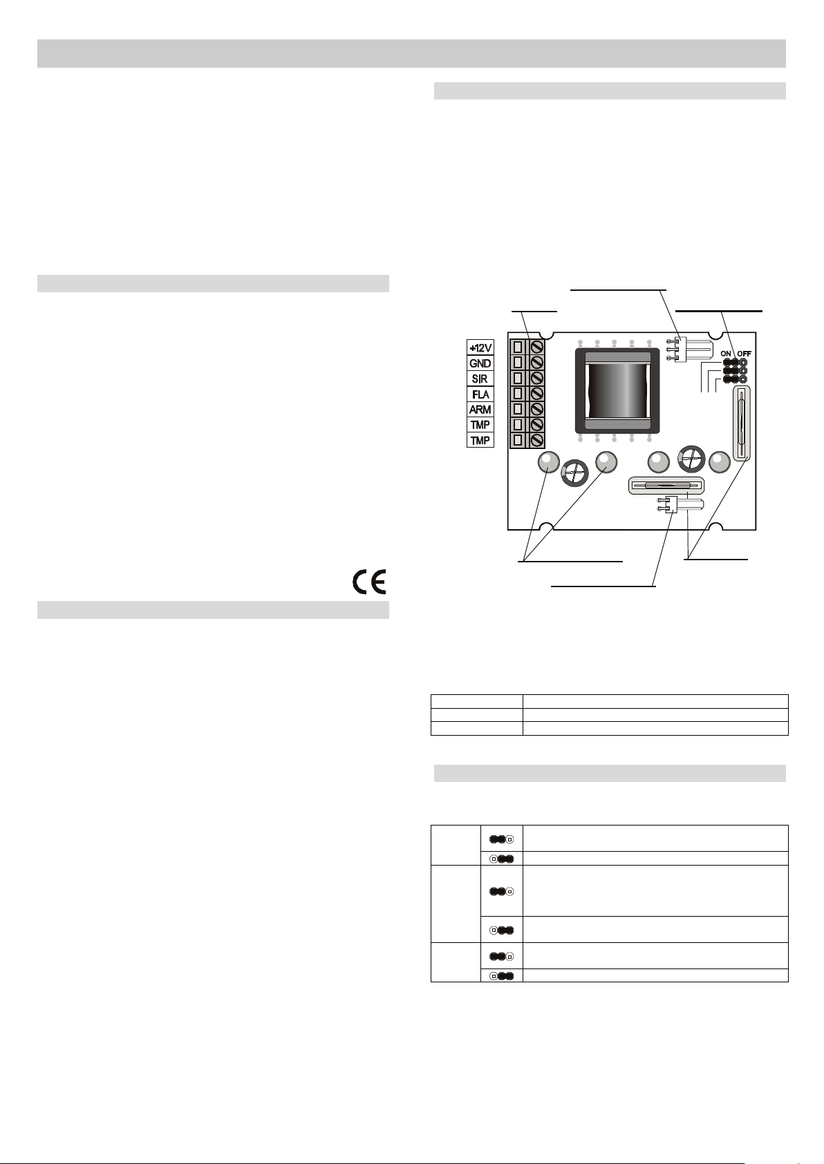
The terminal block connections
+12V - power voltage (+10 to 17V)
GND – ground
Power supply voltage drops cause the siren and the flasher to activate.
SIR - disconnection from GND will cause activation of the siren.
FLA – disconnection from GND will cause activation of the flasher.
ARM – a terminal for additional features. Its function depends on the
setting of the CHIRP and FLASH jumpers (see table 2).
TMP, TMP -
68R protection resistor)
NC tamper switch output (connected in series with the
There are also NiCd backup battery and siren connectors. The NiCd
backup battery comes from the factory disconnected. Only connect it
during installation.
Picture 1 the top side of the electronic circuit board
Terminals ARM , FL A and SIR can also be used for the remote
measurement of the backup battery voltage without the necessity of
climbing up to the siren. Measurement is always made on a single
disconnected cable against GND, directly in the control panel – see
Table 1.
Table 1
The setting jumpers
There are three jumpers on the PCB (Picture 1 shows their location)
to select the optional functions:
CHIRP
FLASH
(connection of FLA to GND)
Any change on the ARM line will terminate flashing
The OS-360/365 outdoor siren 1 MGZ 51203
OK
Table 2
Page 2
Finishing installation
JA-63K(R)
2k2
L4 set to tamper
PGY set to ARM
(see also the control panel manual)
CHIRP
FLASH
OK
ON
ON
OFF
measurem en t s po i nts
-
see Table 1
(if remote measurement is not needed, then it is possible to
connect the SIR and FLA terminals to GND n the sirendirectly i
measurement points
-
see Table 1
JA-65K
2k2
CHIRP
FLASH
OK
OFF
ON
ON
Internet: www.jablotron.com
tel.: 483 559
999
fax: 483 559 993
Pod Skalkou 33
466 01 Jablonec nad Nisou
The following conditions are necessary for the OS-360/365 to be
ready:
1. SIR terminal connected to GND
2. FLA terminal connected to GND
3. Connected and charged NiCd battery (voltage higher than 4 V)
4. Power supply connected to the +12 V and GND terminals
The siren will flash once after 2 seconds and if the battery is charged
enough the siren will shortly sound in 45 seconds to confirm
operational readiness. If the battery is discharged the start-up cycle is
repeated until the battery is charged enough. This will be confirmed by
a short siren sound.
Functions:
Power supply failure will cause the activation of both the siren and
flasher. W hen the power supply is restored siren, sounding and flashing
will be terminated in 3 seconds. If the power supply is permanently
disconnected, the siren will be switched off automatically in 5 minutes.
Disconnecting SIR from GND - will cause the siren to be activated
(but without flasher activation). If SIR is connected back to GND the
siren sounding will be terminated immediately. Otherwise the siren will
be automatically deactivated in 5 minutes.
Disconnection of FLA from GND - will cause the flasher to be
activated (but without siren activation). If FLA is connected back to
GND, flashing will be terminated immediately or in 60 minutes
depending on the settings (this time can be shortened by any change
in the ARM input). There is no limit on flasher activation – flashing will
continue until the FLA input is connected to GND.
Change of ARM input – if the CHIRP jumper is in the ON position,
then on connection of ARM to GND the siren will make one chirp and
the flasher will flash briefly. On disconnection from GND the siren will
make two chirps and the flasher will flash twice.
If the flasher is flashing due to FLA activation, then any change in the
ARM input (connection or disconnection from GND) will terminate the
flashing. (The FLA terminal must be deactivated – connected to GND).
Stand-by – if the SIR and FLA inputs are connected to GND, there is a
proper power supply, the backup battery is charged and the OK jumper
is in position ON, then the siren will flash once every 45 seconds.
Example of use
In this configuration the siren and the flasher are activated during an alarm
from the control panel. Arming and disarming are confirmed by chirps.
Flashing is terminated immediately after disarming the control panel
regardless of the setting of the FLASH jumper. The battery voltage can be
measured at the measurement points shown – see Table 1.
Picture 3 – example of connection to the JA-–65Kcontrol panel
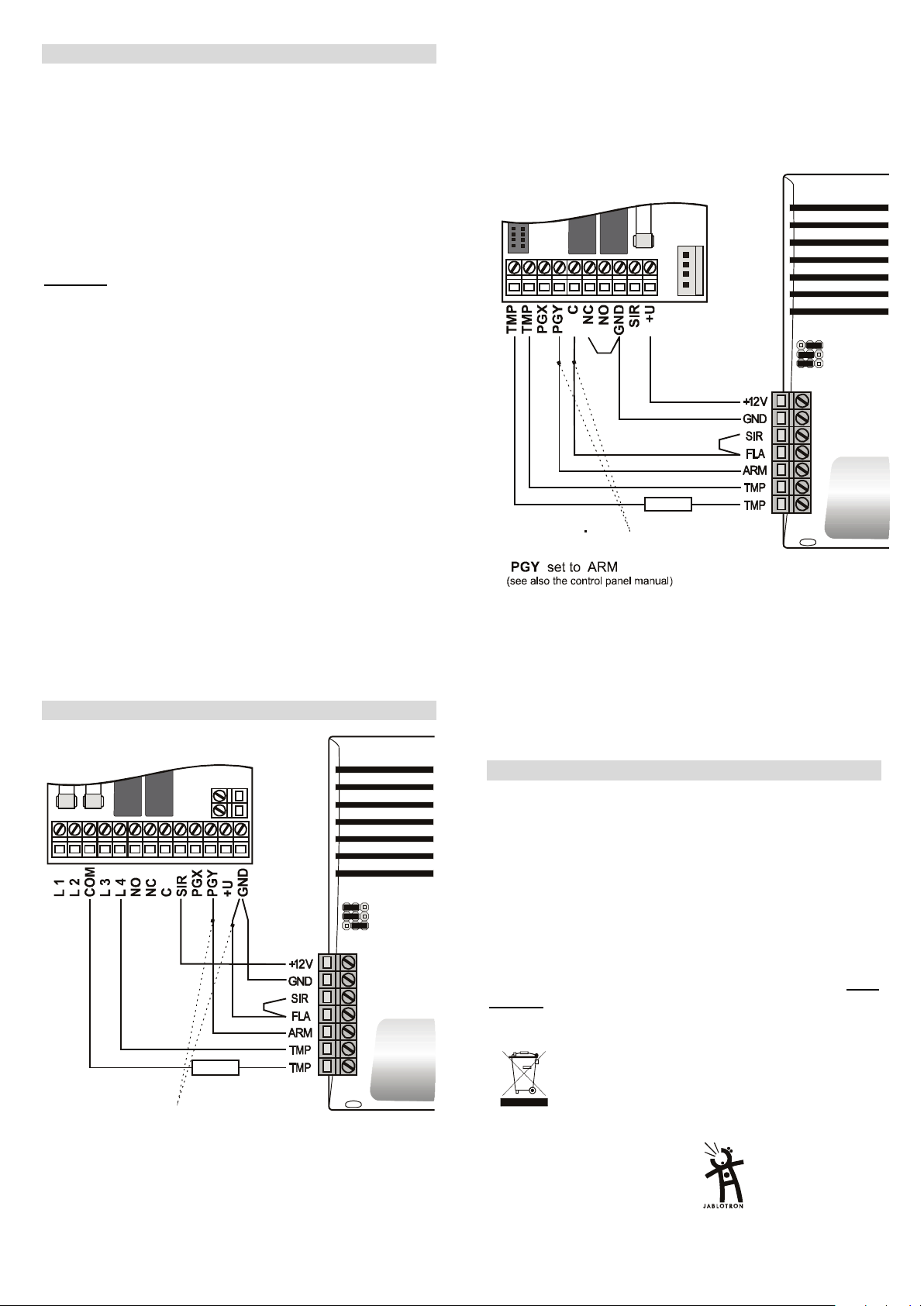
In this configuration, the siren sounds for the duration of the alarm.
Additionally the flasher flashes for another 60 minutes. Flashing can be
terminated by arming or disarming. The chirps are disabled and the flasher
will flash once every 45 seconds to confirm operational readiness of the
siren. The battery voltage can be measured at the measurement points
shown– see Table 1.
Picture 2 example of connection to the JA-63K(R) control panel
The OS-360/365 outdoor siren 2 MGZ 51203
Maintenance
The siren does not need any special maintenance. The lifetime of the
NiCd battery is about 3 years, depending on the working conditions. If
the power supply (+12V and GND) is cut off for longer period of time,
then also disconnect the battery. The battery can be checked remotely
(see Table 1).
Note:
In order not to activate the siren before disconnecting the power
supply, first disconnect the battery.
Warning! If the siren is activated when the siren
connector (see picture 1) is being disconnected, the
siren will not be damaged, but there will be high
voltage on the terminal.
Note: There is NiCd battery containing Cd (cadmium)
Although this product does not contain any harmful
materials we suggest you to return the product to the
dealer or directly to the producer after usage.
 Loading...