

Page 1
JA-65 “MAESTRO” Alarm system
Installation manual
Page 2

This manual is valid for control panel model
JA-65 versions FM61107
(control panel board)
and DY61229
(telephone
communicator board).
The use of Comlink Windows v. 53 software or higher is required for this control panel and can be obtained from our home
page at WWW.JABLOTRON.CZ
Page 3

Contents:
1. Architecture of the control panel 4
2. Configuration of the control panel 5
3. Control panel installation 5
3.1. Power cable wiring 5
4. Antenna of the JA-65R module 5
4.1 Rubber antenna use in the control panel 5
4.2 External antenna use 6
5. Connection of a telephone line to the JA-65X module 6
6. Connectors and terminals of the main board 6
7. The JA-65H hard wired input module terminals 7
8. Wiring of the JA-60 keypad(s) 8
9. Installation of wireless items 8
10. Back up battery installation 8
11. First powering of the control panel 8
12. Control panel programming 9
12.1. Enrollment (teaching) of wireless items 10
12.2. Hard-wired zone input setting 10
12.3. Exit / Entrance delay 10
12.4. Alarm duration 11
12.5. PgX and PgY output functions 11
12.6. Recorded message and phone number editing in the user mode 11
12.7. Radio signal jamming testing 11
12.8. Regular communication checking 11
12.9. Reset enabled 12
12.10. Enrollment of the control panel to a UC-2xx or to a master control panel 12
12.11 No code requested for F1, F2, F3, F4 & F9 12
12.12. Partial (Home) arming with (F2) (non split control panel) 12
12.13. Hard wired siren alarm enabled 13
12.14. Exit delay audible indication 13
12.15. Partial arming exit delay audible indication 13
12.16. Entrance delay audible indication 13
12.17. Arming and disarming chirps with hard wired siren 13
12.18. Siren alarm in Disarm & Partial arming 13
12.19. Wireless siren alarm 14
12.20. Indication of system problems when arming 14
12.21. Control panel splitting 14
12.22. Addressing of wireless detectors to sections 14
12.23. Addressing of the user codes to sections 14
12.24. Addressing of wireless controllers to sections 15
12.25. Automatic arming / disarming setting 15
12.26. New service code setting 15
12.27. Real time and date setting 16
13. System testing 16
14. Voice & Pager message setting 16
14.1. Telephone number entering 17
14.2. Voice message(s) recording 18
14.3. Telephone dialer testing 18
14.4. Dialing method 18
14.5. Telephone dialer triggering 18
14.6. Telephone line checking 18
15. To enable a remote computer to dial in 19
15.1. Reaction to an incoming call 19
15.2. Remote access code setting 19
16. Monitoring station communication setting 20
16.1. Reporting code setting 20
16.2. Account code setting 21
12.3 Protocol and Format setting 21
16.4. Re-dialing pause setting 21
16.5. Phone number entering 22
16.6. Digital communicator reset 22
17. Control panel factory default reset 22
18. Monitoring station report code table 23
18.1. Internal structure of Contact ID protocol 24
19. Personal Computer Interface with PC-60A 25
20. Remote access to the system 26
20.1. Establishing connection with a remote control panel 26
21. Recommended Professional installer basic rules 26
22. Trouble shooting table 26
23. Possibilities to extend the system 27
24. Control panel specifications: 34
Page 4
Alarm system JA-65 MAESTRO - 4 - MFM51202
This product is to be installed by professional installers only. The manufacturer assumes no liability for damages caused by incorrect
installation or improper use of this system.
1. Architecture of the control panel
The JA-65 "Maestro" is a fully programm able control panel with b uilding block architec ture. This allows th e JA-65 to be
tailored to particular installation requirements. The Maestro can operate as a wireless, wired or combined system.
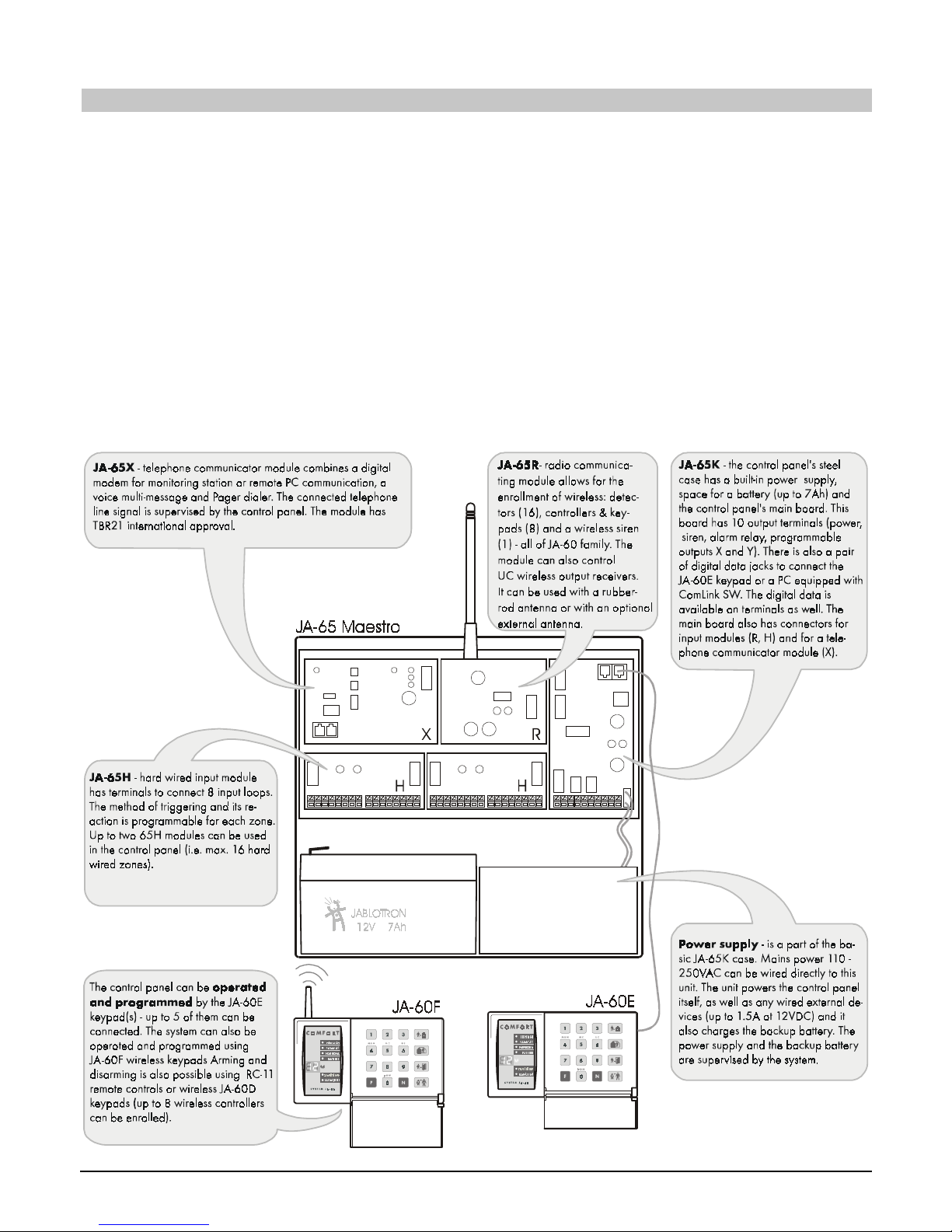
The JA-65K m etal box has a bu ilt in electronic power suppl y. There is spac e for a 12V, 7Ah back up b attery. The 16
zone control panel’s main board is installed in the int ernal platform. The main board do es not have any physical zone
inputs. This allows you to co figurate the control panel by using the following modules:
• Radio communicating module JA-65R can enroll wireless item s (JA-60): up to 16 detec tors, up to 8 contr ollers
(remote controls or wireless keypads), a JA-60A wireless siren and UC family wireless output modules.
• Hard-wired input module JA-65H has 8 input loops with programmable triggering (NC, balanced or double
balanced) and program mable reactions. Up to two JA-65H hard- wired input modules can be used in the c ontrol
panel.
• Telephone communicator JA-65X can communicate with a Monitoring Station, send voice messages and dial a
numeric Pager. It can also communicate with a remote PC (using ComLink SW and a JA-60U modem).
• Operation and programming is possible via the J A-60E ke ypad (or by its wireles s option, JA-6 0F). The co ntrol
panel can also be operated by an RC-11 or RC-22 remote control or by a JA-60D wireless keypad. Operation and
programming is also possible via a PC using ComLink SW.
This allows the JA-65 to operate as a wire less (16 detec tors), wired ( 8 or 16 inputs ) or combine d system. An additional
JA-60 or JA-65 subsystem control panel can expand the system . The control panel can be split in to two independent
sections with a shared common area.
Page 5
Alarm system JA-65 MAESTRO - 5 - MFM51202
2. Configuration of the control panel
The metal case of the JA-65K control pa nel is shipped from the factory with a built-i n power supply unit and the main
board. To be able t o work as an alarm s ystem, it should be equippe d with interface modules (R, H, X) in the follo wing
way:
• open the case and remove the cover
• disconnect the power unit cable from the main board connector K5
• unscrew the module platform (screw on the left side)
• open the platform and remove it from the case
• attach the desired modules to the positions shown in the previous diagram
• connect the modules' cables to the main board in the following way:
o 65X = K1
o 65R = K2
o 65H = K3 (if two 65H m odules are used, co nnect the l eft module c able to t he righ t 65H
module and the right module cable to the main board's K3 connector)
3. Control panel installation
The control panel’s c ase is designed to b e attached to the wal l, or it can be partl y installed int o the wall. T he rectangular
hole on the back side is for cable routing. The hole m atches a KT-250 standard junction box. This allows for easy
specification on how to prepare cables in a house before an alarm system installation.
• If the 65R radio-communicating module is used, keep in mind that the antenn a will need about 20 cm of
clearance. The 65R module com es with a rubber antenna, but it can also be used with an ex ternal antenna ,
model AN-01. The working range of the wireless accessories is about 100 meters under optimal conditions.
However, buil ding materials can abs orb or obstruct radio s ignals and comm unication can also be ef fected by
interference f rom other r ad io si gnals. For thes e re aso ns , you sh oul d ant icipa te a s hor ter work ing r ange f or ind oor
installations.
• Before attaching the case to the wall, remove the power supply unit (two screws from the front side)
• Route all the cables to the c ontrol panel (power, inp ut loops, outputs, telephon e line etc.) before you att ach
the case to the desired location.
Note: if you inst all the c ase in the w all, th e hinges for both t he cov er & modu le mount ing platform s houl d not be pl aced
within the wall.
3.1. Power cable wiring
The power cable should be connected only by a licensed electrician. The control panel is a class II. device with
double insulation a nd power to its po wer unit must be wired with double insulated t wo core power cord. No power wire
should be connected to the metal case. Instructions:
• use flexible 2 core (size from 0.75 to 1.5 mm
2
) double insulated power
cord. The system should not share a fuse with any other household item.
• route the power cable thro ugh the plastic bush ing of the power supply unit
cover and screw its wires tightly to the AC terminals
• attach the cable firm ly to the board using the pl astic bracket. Before you
tighten the bracket, check that the wires are tightly screwed in the
terminals and be sure that the wires are not longer than shown in the
diagram.
• reattach the power supply unit in the case, but do not switch the power on
• install the module m ounting platform to the case and connect t he power
unit cable to connector K5 on the main board .
Warning: never open the cover of the power supply unit when the system is powered!
4. Antenna of the JA-65R module
If the JA-65R module is installed, it will be possible to enroll wireless detectors,
controllers, a JA-60A siren, output modules and another wireless subsystem if
required. Enrollm ent is described in the part 9. T he 65R module m ust be equipped
with an antenna.
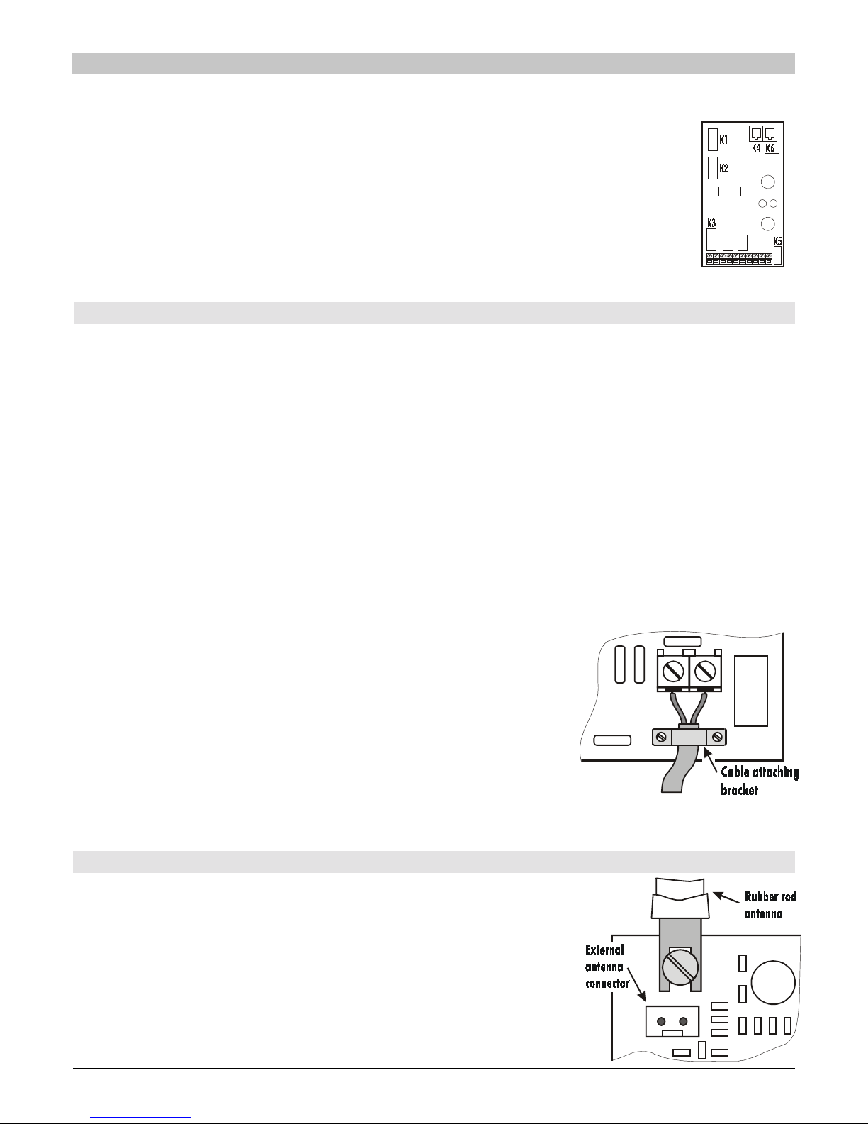
4.1 Rubber antenna use in the control panel
There is a hole on the top of the control pane l case (rem ove the plastic c ap) for the
rubber antenna. The rubber antenna is supplied with the 65R module. Install the
antenna after the module mounting platform is inserted and screwed inside the
control panel case. Attac h the antenn a to the 65R bo ar d using a sc rew as sho wn in
the diagram. The antenna must not be obstructed by any large metal object.
Page 6
Alarm system JA-65 MAESTRO - 6 - MFM51202
4.2 External antenna use
An optional externa l antenna, m odel AN-01, c an be us ed with the 65R m odule. T his antenna has a connector , which fits
the connector on the 65R module. If you use the external an ten na, t he r ub ber an tenn a s hou ld n ot be ins ta lle d. The AN-01
antenna has a small plas tic ring on its en d, used to hang i t from the wall. Its active part ( from the plastic ring to the coi l)
should be installed ver tically an d should not be o bstru cted by an y large m etal object. T he antenna can b e located behi nd
furniture, etc.
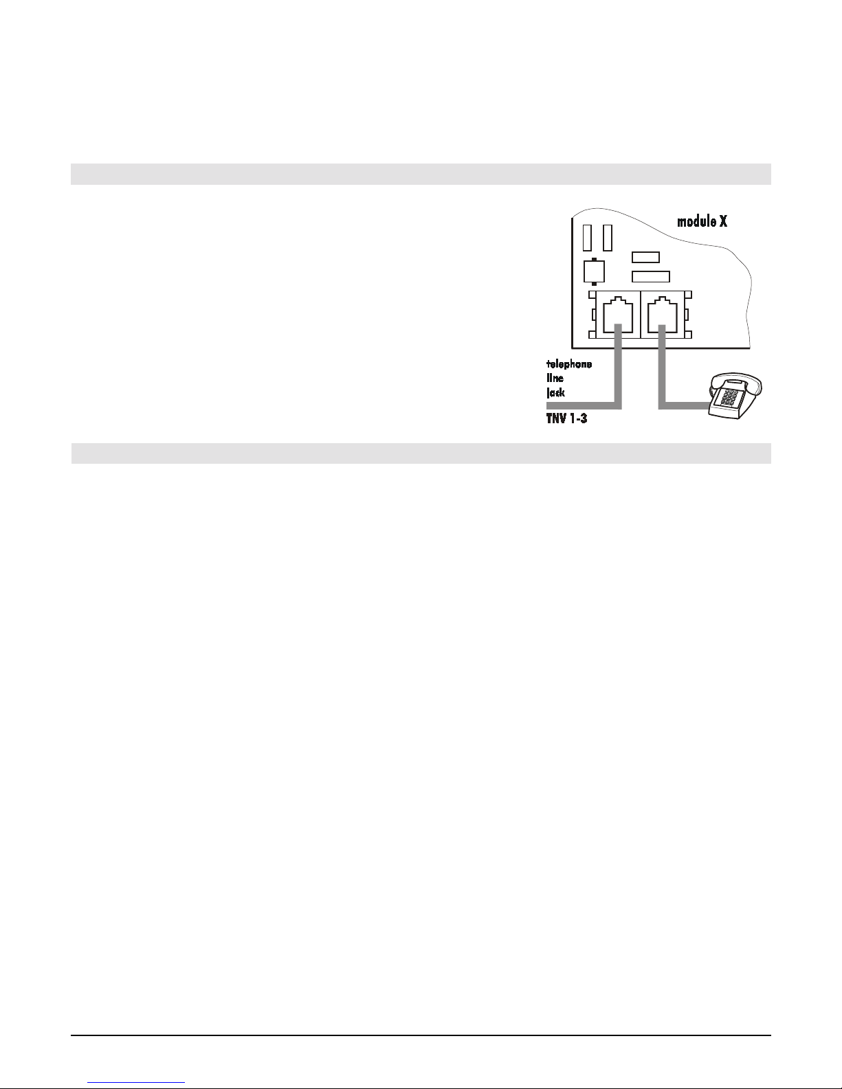
5. Connection of a telephone line to the JA-65X module
If the JA-65X module is installed, the control panel can communicate with a
Monitoring Station, s end voice messages and d ial a numeric Pager as well as
communicate with a r emote PC. A s tandard analog t elephone line ( type TNV 1-
3) must be connected to the 65X module for these functions.
• Use the provided telephone cable to connect the telephone line to the IN
jack in the 65X module (see diagram )
• Connect a telephone, fax or other phone operated device to the OUT jack,
marked with a phone symbol
• When the control panel is in normal stand by mode, the phone line and any
attached device will operate as normal
Note: The communicator must be plugged directly to a telephone line socket.
All other devices (telephone, facsimile machine, modem etc.) should be
connected to the communicator output.
6. Connectors and terminals of the main board
In addition to the interface module connectors (K1, K2 and K3) the main board has the following connectors:
K5 - power supply connector: the cable from the power unit is connected to this . By disconnecting t his cable you
completely power-down the system (for example, when you perform a factory default reset).
K4, K6 - digital data jack s for the J A-60E keypad(s) an d/or for a PC inte rface cabl e. Up to five JA-60 E keypads can
be connected to a JA- 65 a nd the m ax imum lengt h of the cab le ca n be 5 00 m eters. W e rec omm end use of a CT- 04 cable
and RJ-44 (Jablotron) crim ping c onnect ors to m ake the k e ypad cables. T he digita l data is also a vaila ble on the ter m inals:
see the following description.
1,2,3,4 - digital data terminals (see K4, K6) provide an option to use standard cable for the wiring of JA-60E keypads. The
keypads are also equipped with both jacks and terminals.
The following terminals are on the bottom side of the main board:
TMP a pair of terminals to c o nne c t the tamper switch of an ex ternal de vic e ( f or ex ample: a wire operated out door s iren,
OS-300). In normal use, thes e terminals should be c onnected together via a 10k r esistor. Triggering of this loo p
has the same effect as control panel tampering (a change of ±30% or more of the End Of Line resistor wi ll trigger the
input).
PGX is an output (t rans i stor swit ching to GND, max. 12V , 1 00mA) . The fun ctio n o f t hi s o utp ut i s de te r mined by the settin g in
the programming mode (see 12.5). The control panel also wirelessly transmits the PGX signal and unit UC-216 or
UC-222 can be used as a remote output of this signal.
PGY is an output (t ransistor switching to GND, max. 12V , 1 00mA). The fun ctio n o f t hi s outp ut is determined by the se ttin g in
the programming mode (see 12.5). The control panel also wirelessly transmits the PGY signal and unit UC-216 can
be used as a remote output of this signal.
C is a common contact of the alarm output relay, max. load 60V / 1A. The relay is turned on during any alarm of the
control panel.
NC is a normally closed contact of the alarm output relay.
NO is a normally open contact of the alarm output relay.
GND is a common ground terminal of the power output (-). This terminal is also available on 65H modules.
SIR is an external siren output. In the normal mode it has the +U terminal voltage. In the alarm mode it has a GND terminal
potential. Connect an ordinary external siren to +U and SIR terminals (max. load 1A). A back up siren charging input
should be connected to the GND and the SIR terminals (during an alarm, the charging will temporarily halt). The siren
can also be used for sounding arming and disarming chirps and as an audible indicator while in the testing mode.
+U is a back up power output for external items (detectors etc.). A positive voltage on this terminal is a duplicate of the
backup battery voltage. The permanent load should not be higher than 1,5 A. This output is fused and supervised by
the control panel. If it is overloaded, a control panel failure will be indicated (fault C). The multiple +U terminals are also
Page 7
Alarm system JA-65 MAESTRO - 7 - MFM51202
available on the JA-65H hard-wire modules for easier wiring. All +U terminals are connected in parallel to the +U
terminal of the main board.
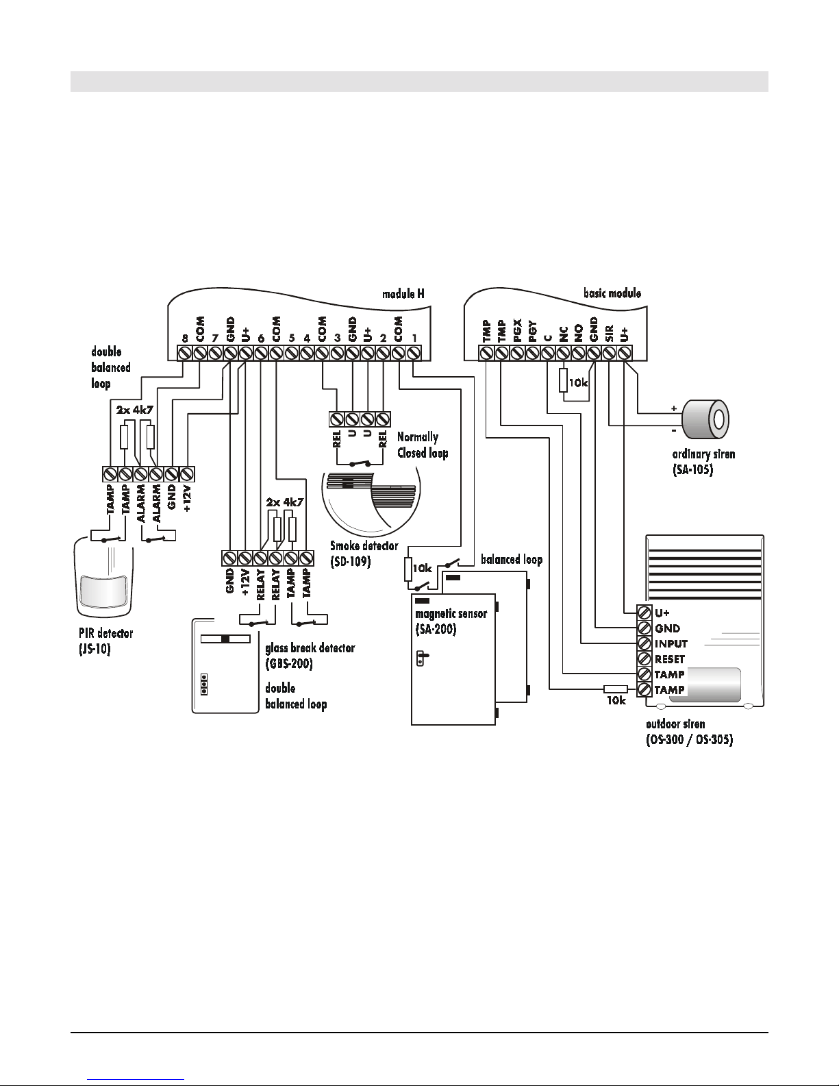
7. The JA-65H hard wired input module terminal s
Up to two 65H modules can be us ed i n the contr ol pa nel. T he m odule with its ca ble co nnecte d direc tly to th e m ain board
provides zone inp uts 1 to 8 . If the s econd m odule is install ed it wil l provide zone i nputs 9 to 16. The 65H m odule has the
following terminals:
1 to 8 zon e inputs – N ormally, detector outputs are wired here: see exam ples of wiring in diagram . For each input it is
possible to program its method of triggering: Norm ally Closed loop, balanced loop ( 10kΩ) or double balanced
loop (2x 4k7) and the type of reaction of the system (see section 12).
COM Four common terminals to close (balance) the input loops
GND ground (negative pole) of the power supplier
+U backup powe r outp ut for externa l devic es (det ectors etc.) , max. t otal c onsum ption f orm all +U ter minals in the c ontro l
panel can be 1.5A.
Example of t he JA - 6 5 con t rol panel w irin
g
Page 8
Alarm system JA-65 MAESTRO - 8 - MFM51202
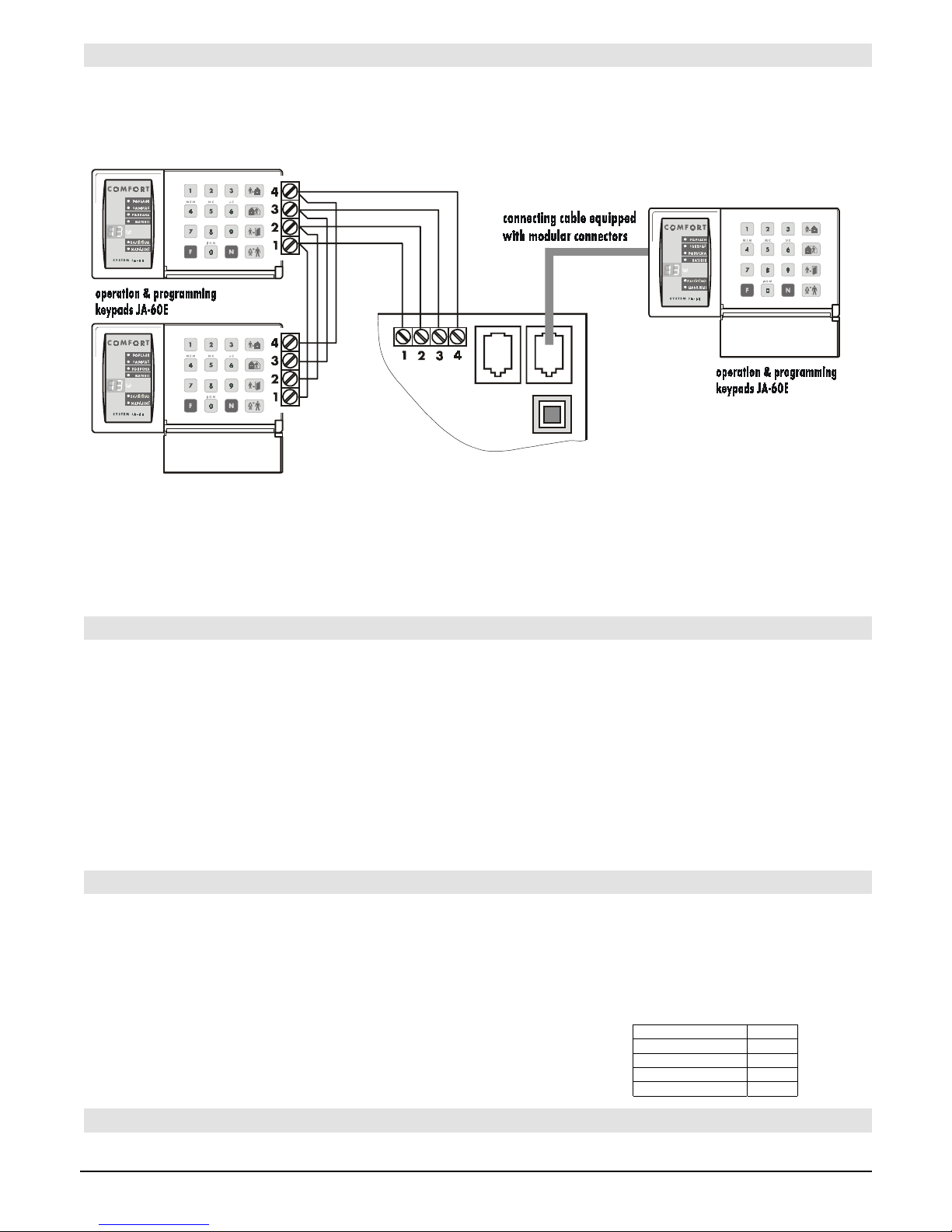
8. Wiring of the JA-60 keypad(s)
The system can be progra mmed and operated by JA-60E keypad(s ). As a maximum, 5 keypads can be wired to th e
control panel. The k eypads can either be wired by cables equ ipped with modula r jacks to connectors K4 and K5 or b y
standard cables to terminals 1,2.3 & 4 on the main control panel board. The same numbered terminals (pins in the
connectors) must be linked together. It is possible to combine arbitrary wiring with modular connectors and ordinary
cables - see diagram.
When a control pan el has a JA-65R radio c ommunicating m odule insta lled, it can a lso be operat ed and program med
via JA-60F wireless keypad(s) asunder this situation, a minimum of one JA-60E keypad should be connected to the
control panel. With a 65R module, the system can also be operated by remote controls RC-11 & RC-22, as well as by a
JA-60D wireless keypad. The control panel can have up to 8 wireless controllers.
It is also possib le to operate and program the J A-65 system via a connect ed PC with SW ComLink. T he PC can be
connected locally with a PC-60A interface cable or remotely, using a JA-60U modem (see section 19 and 20).
9. Installation of wireless items
If the control panel is equipped with a JA-65R module, it can work with all types of JA-60 wireless items and wireless UC
output modules (see brief overview of items in section 25.1).
• Detectors - one wireless JA-60 detector can be enrolled to each control panel zone (i.e. up to 16 detector)
• Keypads and remote controls - up to 8 wireless controllers can be enrolled to the control panel (JA-60F and
JA-60D keypads, RC-11 and RC-22 remote controls)
• JA-60A Wireless siren - only one can be enrolled to a control panel
• wireless output modules UC-216 and UC-222 have relays, which copy the status of the control panel’s
programmable outputs PgX and Pg Y. An unlimited number of the UC modules can be used with each system.
Follow the particular wireless item manual when installing. After you install the item to desired location, leave it un
powered and without its cover. The method of enrollment is described in section 12.1.
10. Back up battery installation
there is a space for size 12V, 7 Ah batter y. Accordin g to the des ired backup p eriod a 12 V back up ba ttery from 1.3Ah to
45Ah can be used instead. A battery larger than 7Ah must be installed in an external case and the case must be
equipped with tamper protection.
The control panel recharges an d check s the condit ion of the back up battery. If the system is powered from the battery
for a long time and t he batter y is nearly d ischarged, the c ontrol pan el will fir st trigger a tec hnical a larm and i t will then
disconnect the batt ery to pr event dam age. Af ter the m ain power is o n aga in, th e
battery will be re-connected and will automatically re-charge.
• insert the battery into the control panel
• connect the battery cables (red +, black - )
Warning
- do not make any short connection of the battery terminals!
11. First power ing of the control panel
• Check that all cables are connected correctly
For battery back up time calculation use the
following stand-by consumption rates:
module JA-65R 20mA
module JA-65X 12mA
module JA-65H 15mA
main b. JA-65K 10mA
keypad JA-60E 25mA
Page 9
Alarm system JA-65 MAESTRO - 9 - MFM51202
• Switch on the AC power
• The keypad will display a "P", confirming that the system is in the programming mode (for system setting, enrollment of
wireless items and for testing).
Note: if „P“ is not displayed, the control panel is not in the factory default setting. Perform a Factory default reset. (See section 17).
12. Control panel programming
Functions of the system can be customized. The most convenient programming method is via a connected PC using the Comlink
software (see 19). Programming can also be performed by entering programming sequences from the system keypad while in the
programming mode:
• If the control panel is not in the programming mode, open it (entering F 0 SC - SC = Service Code, factory default SC=6060) –
The programming mode will be indicated by a „P“ on the LED display. This mode can only be entered when the panel is
disarmed. In this mode, no alarm can be triggered. Detectors and other accessories can be enrolled, the system parameters
can be set up and the system can be tested.
• The parameters of the control panel can be set by entering programming sequences from the keypad. Any unfinished
programming sequence can be terminated by pressing the N key.
• To exit the programming mode, press the N key („P“ will turn off). If any fault is indicated when you try to exit the
programming mode, the control panel will inform you of the problem (see programming sequence 39x for more details).
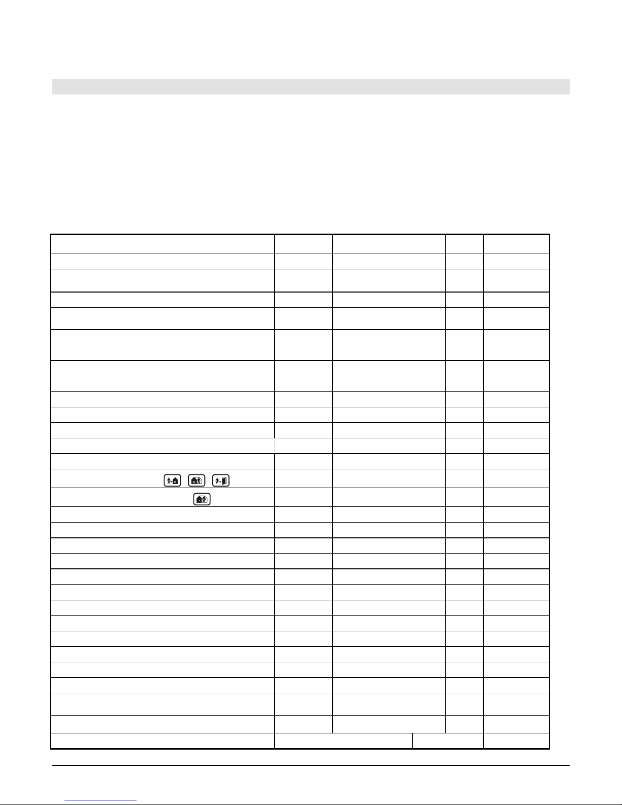
List of control panel programmable parameters
Function sequence
options
factory
d.
note
Enrolling of detectors and controllers
1
1& 7 scroll, 2 erase pos., 4 all
-
w. R module only
Hard-wired zone input setting 60 nn xyz
nn– zone n., x– triggering,
y– reaction, s- section
all off
w. H module only
Exit / Entrance delay
21x
x = 1 to 9 (x 10sec.)
30sec.
Alarm duration
22x
x = 1 to 8 (min.), 0=10s,
9=15min
4min.
Function of PgX output
23x
x = 0 to 7 (0-Chime, 1-Fire, 2-
Arm, 3-Panik, 4-Al arm, 5-Door,
6-Home, 7-No AC
Chime split system has
different setting
Function of PgY output
24x
x = 0 to 7 (0-Chime, 1-Fire, 2-
Arm, 3-Panik, 4-Al arm, 5-Door,
6-Home, 7-No AC
Arm split system has
different setting
Voice m. & tel. Numbers editable in the user mode
25x
251 = YES 250 = NO
NO
w. X module onl y
Radio signal jamming regular testing
26x
261 = YES 260 = NO
NO
w. R module only
Regular communication check enabled
27x
271 = YES 270 = NO
NE
w. R module only
RESET enabled 28x
281 = YES 280 = NO
YES
Control panel teaching to a UC-2xx, subsystem,...
299
will send enrolling signal
w. R module only
No code requested (effects
, ,
, F4 & F9)
30x
301 = YES 300 = NO
YES
Partial (Home) arming enabled ( )
31x
311 = YES 310 = NO
YES
Siren alarm enabled
32x
321 = YES 320 = NO
YES
Exit delay audible indication enabled
33x
331 = YES 330 = NO
YES
Partial arming exit delay audible indication
34x
341 = YES 340 = NO
NO
Entrance delay audible indication enabled
35x
351 = YES 350 = NO
YES
Arming & disarming chirp sounds enabled
36x
361 = YES 360 = NO
NO
Siren in Disarm & Partial arming enabled
37x
371 = YES 370 = NO
YES
Wireless siren alarm enabled
38x
381 = YES 380 = NO
YES
w. R module only
Indication of system problems when arming
39x
391 = YES 390 = NO
NO
Split control panel (A, B & C sections) 690x
6901 = YES 6900 = N0
NO
Addressing of wireless detectors to sections 61 nns
nn– zone n., s- section
1-10 A
w. R module only
Addressing of user codes to sections 62 nns
nn– code n., s- section
all A
only when split
Addressing of wireless controllers to sections 63 nns
nn– controller n., s- section
all A split & R module
Automatic arming/disarming setting
64nahhmm
n- 0-9, a-action #, hh-hours,
mm-min.
all off spl i t & partial
arming see 12.21
New Service Code setting
5
nSC nSC
nSC = new Service Code
6060 enter code twice
Real time and date setting
4 hh mm DD MM RR
00 00 01 01 00
Page 10

Alarm system JA-65 MAESTRO - 10 - MFM51202
12.1. Enrollment (teaching) of wireless items enter: 1
If the control panel has a 65R module, as a maximum 16 wireless detectors and 8 controllers (remote controls & keypads)
can be enrolled to the control panel. A wireless siren and an additional JA-60 or JA-65 control panel (a subsystem) can be
enrolled as well.
• press ke y 1 (while „P“ is d isplayed) to enter the e nrolling m ode. The contr ol panel will displa y the next f ree posit ion
to enroll a detector.
• Use key 1 and 6 to scroll (up and down) all control panel wireless positions – 1 to 16 (detectors) – c1 to c8
(controllers & k eypads) – A (wireless s iren) – J (sub control panel JA-6x). The disp lay shows the positio n number
while the Battery LED indicates if the position is occupied.
• Detectors and keypads are automatically enrolled when their power is switched on (batteries are installed). A
remote control is enrolled only after both of its buttons are simultaneously pressed and held for 3 seconds. A
subsystem control pa nel wi ll enr o ll af ter s eque nce 299 is entered while it is in its program ming mode. The system will
not allow enrollm ent of an item into a non-corresponding posit ion (a detector can not be enrolled into a c ontroller
position etc.).
• Control panel confirms enrollment with a „b eep“ (press F to select a l ouder “beep” sound). The L ED display will
show the number of the enrolled item for 2 seconds and then it will display the number of the next free position.
• To change the position of an enrolled item is simple. Enroll it to the new selected position (the item will „move“).
If you enroll an item to an occupied position, the former item will be deleted and only the new enrollment is valid. Only
one item (detector, controller etc.) can be stored to each position.
• Erase an enrolled item the following way: in the enr olling mode select t he corresponding position and then pr ess
and hold key 2 for tw o sec o nds . The item will be erase d ( confirmed with a long b e ep) . If you pres s a nd h old key 3, all
enrolled controllers (r emote controls and k eypads) will be erased. Pr essing and holding k ey 4 will erase all enrolled
items (detectors, controllers, siren and the sub system).
• The JA-60A wireless siren will generate an enrollment signal when its power is switched on (it will enroll to
position A). If you need t o enrol l a siren which is already powered and it is not possible to easi ly switch of f its power ,
you can enroll it t he fo llowing wa y: enter the enrol ling m ode and the n enter the 6 digit s iren produc tion co de (printe d
in the siren’s manual). T he control pane l will “reques t” the siren to send its enrollm ent signal. The s iren will send the
signal only if it has no current communication with any other control panel (This pr otects you from enrolling your
neighbor’s siren). Enrollment is completed about five seconds after the code is entered.
Note: if an item was not enrolled after its batteries were installed, it is because the control panel recognized its radio signal as a weak
one. Items are only enrolled if their radio signal has a level which guarantees reliable communication. Check the detector’s batteries
and try to enroll the problematic sensor once more. If it is not accepted by the control panel, you should change the location of the item.
All items should be located 1 m or more from the control panel.
12.2. Hard-wired zone input setting sequence: 60 nn xys
If there is a 65H module in the control panel, wire operated detectors can be connected to the control panel. Setting of the
zone inputs is possible by entering:
60 nn xys
where: nn = zone number: 01 to 16
x = input triggering: 0 = of f, 1 = Normally Closed, 2 = balanced loop (EOL r esistor 10kΩ), 3 = double
balanced loop (EOL resistors 2x4k7Ω)
y = reaction: 0 = Instant, 1 = Delayed, 2 = Fire, 3 = Panic, 4 = Tamper, 5 = Next delayed
s = address to section, 1 = A, 2 = B, 3 = C (shared common section, which is armed only if both A and B
sections are arm ed) . If the c ontrol pa nel is not s plit, s e lec t s =1; if you select s =2 t hen this zone will b e
automatically bypassed within partial arming. For details about splitting see section 12.21.
Notes:
• If you will not use a particular input, switch it off with x = 0
• Next delayed input (y=5) provides entrance delay only if in the moment of its triggering the entrance delay has been in progress
(activated before by any delayed input). If no delayed input is triggered before next delayed, the triggering will cause instant alarm.
• Addressing of inputs to section C when the control panel is not split has the same effect as addressing to B section (i.e. automatic
bypass while partial arming is used).
Example: to set zone 2 input as a balanced loop with an instant reaction, addressed to A section, enter: 60 02 201
Factory default setting: all hard-wired inputs are switched off.
12.3. Exit / Entrance delay sequence: 2 1 x
To change the duration of the exit and entr a nce de lay (both of them) enter 21x (where x represe nts time in seconds x10) .
The delay can be selected from 10 to 90 seconds.
Example: to select an Exit and Entrance delay duration of 20 seconds, enter 212
Factory default setting is 30 seconds
Page 11

Alarm system JA-65 MAESTRO - 11 - MFM51202
12.4. Alarm duration sequence: 2 2 x
The alarm duration c an be selected from 1 to 8 m inutes (or 10 s econds or 15 m inutes) enter ing 22x (where x r epresents
time in minutes, for x=0 the duration will be 10 seconds, for x=9 the duration will be 15 minutes).
Example: to select an alarm duration of 5 minutes, enter 225
Factory default setting is 4 minutes
12.5. PgX and PgY output functions sequences: 2 3 x & 2 4 x
The control panel output s PgX and PgY can have different functions , depending on parameter x in the correspond ing
sequence:
2 3 x – determines triggering of PgX
2 4 x – determines triggering of PgY
where x represents the following functions (non split system):
0 Chime – triggered during the entrance delay (pre-alarm output)
1 Fire – triggered by a fire alarm (by a smoke or a gas detector)
2 Arm – activated when the control panel is armed (complete & partial arming)
3 Panic – activated when a silent panic alarm is triggered
4 Alarm – triggered by any audible alarm (except panic alarm)
5 Door – activated for 5sec. after
(F3) entering (electric door lock opening)
6 Home – activated when the control panel is partially armed (Home arming)
7 No AC – triggered by an AC power failure
Example: the PgX will work as a Panic output when 233 is entered, PgY as Door output when 245 is entered.
Factory default setting: PgX=Chime, PgY=Arm
Note: the control panel also wirelessly transmits the PgX and PgY signals. Wireless output modules UC-216 and UC-222 can be used
to receive the signals (see 25.1.). The function of the UC module output relays is determined by the 23x and 24x setting.
12.6. Recorded message and phone number editing in the user mode sequence: 2 5 x
The User mode, which is accessible with F 0 “Master Code”, is for bypass setting, system testing and battery
replacement. This s etting enables th e user to chang e the voice m essage and te lephone number s of the built in d ialer. If
the changes are enabled, t hen programming sequences f or number programming, voice m essage recording and dialer
testing are accessible in the User mode. These settin gs have effect onl y wh en th e c on tr ol pa nel has a 65X c ommunicator
module.
options:
2 5 1 changes enabled
2 5 0 changes disabled (no dialer programming in the User mode)
Factory default setting: changes disabled
12.7. Radio signal jamming testing sequence: 2 6 x
When this f unction is enabled, the contr ol panel will indicate troub le if the working band is j ammed for more than 30
seconds. Jamming will tr igger an alarm when the contr ol panel is armed. Do not enable th is testing, if the control pane l
does not have a 65R radio module.
options:
2 6 1 testing enabled
2 6 0 testing disabled
Factory default setting: disabled
Note: in some locations the system can be repeatedly jammed for some period of time (near radar, TV or radio station etc.). In these cases the control
panel can work without any problems because all important data is repeated, but the jamming tes t should not be enabled. The level of the si gnals and
interference can be observed usi ng the Comlink software (see 19.)
12.8. Regular communication checking sequence: 2 7 x
The control panel will check communication reg ularly with all enrolled item s (detectors, keypads, siren etc .) when this
function is enabled. If communication is lost with any item, the control panel will indicate the fault of this item (when armed
it will also trigger an alarm). Do not enable this checking, if the control panel does not have the 65R radio module.
If the system is split:
x
23x (PgX) 24x (PgY)
0 Alarm A Alarm A
1 Alarm B Alarm B
2 Chime A Chime A
3 Chime B Chime B
4 Arm A Arm B
5 Door A Door B
6 Panic A Panic B
7 FIRE NoAC
Page 12

Alarm system JA-65 MAESTRO - 12 - MFM51202
options:
2 7 1 checking enabled
2 7 0 checking disabled
Factory default setting: checking disabled
Note: in some locations with a strong radio interf erence (near radar, TV or radio station etc.) the communication can be jammed periodically. The control
panel can detect such a strong interference as a temporary loss of communication with an item. Even in this case, the system is usually able to work
without any problems, becaus e al l i mportant data is repeated, but the communicat i on check should not be used.
12.9. Reset enabled sequence: 2 8 x
The factory default reset ( s ee 17.) c an be d is ab led. This way no unauthorize d f utu r e progr am ming of the control panel wi ll
be possible.
options:
2 8 1 reset enabled
2 8 0 reset disabled
Factory default setting: reset enabled
Note: if the Master or Service code is forgotten when the reset is disabled, the reset of the control panel will be possible only by the manufacturer.
12.10. Enrollment of the control panel to a UC-2xx or to a master control panel sequence: 2 9 9
The control panel can send wireless data to output modules UC-2xx (see section 25.) and it can also work as a
subsystem of another JA-65 or JA-60 control panel.
Enter the enrolling mode of the UC receiving device and then enter 299 and the control panel will generate the
enrollment signal.
If you want to enroll a subsystem to your control panel, enter the enrolling mode o n the MASTER control pane l (see
12.1.) and then enter sequence 299 in the programming mode of the sub control panel.
If the system is split, the sub control panel enrolls to the common shared section.
12.11 No code requested for , ,
,
(F1, F2, F3), F4 & F9 sequence: 3 0 x
If this parameter is enabled, no code is requested for functions F1, F2, F3, F4 and F9 (or the
, ,
,
keys on the
keypad). When this param eter is disabled, th ese functions (ke ys) can be used only when follo wed by a code (Master or
User) – see the following table:
function / setting 300 301
arming „code“ F 1
partial arming F 2 „code“ F 2
door opening F 3 „code“ F 3
memory reading F 4 „code“ F 4
message listening F 9 „code“ F 9
„code“ = Master or User
Factory default setting: no code requested
Note: this feature is al so selectable on the JA-60D w i rel ess keypad and it is independent f rom t he control panel setting.
12.12. Partial (Home) arming with (F2) (non split control panel) sequence: 3 1 x
In partial arming, the contr ol panel reacts only to det ectors addressed to sectio n A (see 12.2 and 12.22) and it ignores
the triggering of detect ors in section B or C (except smoke and gas detectors). Partial arm ing can be disabled with this
sequence.
options:
3 1 1 partial arming enabled
3 1 0 partial arming disabled
Factory default setting: partial arming enabled
Page 13

Alarm system JA-65 MAESTRO - 13 - MFM51202
12.13. Hard wired siren alarm enabled sequence: 3 2 x
The SIR siren output is activated when any alarm is triggered (except silent Panic a larm). The siren indication can be
disabled with this parameter.
options:
3 2 1 siren enabled
3 2 0 siren disabled
Factory default setting: siren enabled
12.14. Exit delay audible indication sequence: 3 3 x
The exit delay can be indicated by the „beepi ng“ of the keypad (for the l ast five seconds, the beep ing is faster). The
audible indication can be disabled with this setting.
options:
3 3 1 indication enabled
3 3 0 indication disabled
Factory default setting: indication enabled
12.15. Partial arming exit delay audible indication sequence: 3 4 x
Partial arming with (F 2) provides a n exit delay for delayed reac tion detec tors in section A. The exit delay for par tial
arming can be indicated by the „beeping“ of the keypad (for the last five seconds the beeping is faster).
options:
3 4 1 indication enabled
3 4 0 indication disabled
Factory default setting: indication disabled
Note: when this indication is disabled, the confirmation of partial arming and disarming will automatically be s ilent, regardless of the 36x s etting.
12.16. Entrance delay audible indication sequence: 3 5 x
The entrance delay can be indicated by a rapid „beeping“ of the keypad. This indication can be disabled with this setting.
options:
3 5 1 indication enabled
3 5 0 indication disabled
Factory default setting: indication enabled
12.17. Arming and disarming chirps with hard wired siren sequence: 3 6 x
An ordinary siren connecte d to t he contro l panel SIR output ca n conf irm arm ing with a loud beep a nd disar ming with two
loud beeps (3 beeps after disarming indicates user information on the LED display).
options:
3 6 1 siren chirps enabled
3 6 0 siren chirps disabled
Factory default setting: siren chirps disabled
Note: setting of chirp sounds is valid even if the siren is disabled for alarms with parameter 320. Partial arming is always s ilent, if sequence 340 is
selected. Chirp sounds can al so be generated with the JA-60A wireless siren (self-c ontained setting in the wireless siren).
12.18. Siren alarm in Disarm & Partial arming sequence: 3 7 x
The SIR output can be dis abled for alarms during the Disarm & Partia l arming of the contro l panel (while som ebody is
indoors). If the siren output is completely disabled for alarms with parameter 320, this setting has no effect.
options:
3 7 1 alarm in disarm & partial arming enabled
3 7 0 alarm in disarm & partial arming disabled
Factory default setting: enabled
Page 14

Alarm system JA-65 MAESTRO - 14 - MFM51202
12.19. Wireless siren alarm sequence: 3 8 x
The wireless siren alarm function can be disab led with this param eter. This settin g will have no influenc e on the outdoor
wireless siren chirp so und func tion if ena bled in the s iren. This setting has ef fec t only when th e control p anel is eq uipped
with a 65R module:
options:
3 8 1 siren enabled
3 8 0 siren disabled
Factory default setting: siren enabled
12.20. Indication of system problems when arming sequence: 3 9 x
The system regularly checks the conditions of all items (detectors, keypads etc.). This setting ensures that the user will be
warned with 4 rapid beeps after arming, if any component of the system is not ready for arming. Cause of the problem (for
example permanently triggered detector, l os t c om munication etc.) will r emain displayed on th e keypad. If the user ign or es
this warning, the s ystem will arm after the ex it delay, then an alarm will be triggered a nd finally the problematic item will
be bypassed for this arming period. After disarming in such a mode, three beeps will be generated as well.
When the indication is not selected, the problematic item will be bypassed when arming with neither warning nor alarm.
If a permanently activated detector is deactivated during arming (for example your main door is not closed), the bypass of
this detector will be cance led automatically and the detec tor will be ready to trigger an alarm aft er it is activated (if you
close the door after the system is armed).
options:
3 9 1 warning enabled
3 9 0 warning disabled
Factory default setting: warning disabled
Note: if this indication is enabled, t he problems will also be indicated if there are any when leaving the programming or user mode.
12.21. Control panel splitting sequence: 690 x
The control panel can be split in to 2 independent sections A and B, with a shared common area C. This way the system
can be operated b y two indepen dent user gr oups. In f act the s ystem in this m ode work s like two in depend ent system s. If
the system is split t o the sections with this setting, i t is possible to address detectors (bot h wireless and wired), user
codes and remote controls to the above sections (see 12.2., 12.22 and 12.23.).
options:
6 9 0 0 no splitting (partial arming available in this mode)
6 9 0 1 splitting to sections A, B and common C (C is armed only when both A and B are armed)
Factory default setting: no splitting
12.22. Addressing of wireless detectors to sections sequence: 61 nns
If the control panel is spl it (see 12.21.) and is equ ipped with a 65R m odule, the wireless detec tors can be addressed t o
sections by entering:
61 nns
where: nn = wireless detector zone number: from 01 to 16
s = section: 1 = A, 2 = B, 3 = C ( c om mon section - it is armed only when both A and B are armed). If the
control panel is not sp lit, and s=2 (or s=3) is selected, th is detector will be bypassed while partial
arming.
Example: to address wireless detector zone number 3 to section A enter: 61 031
Factory default setting: detectors 1 - 10 are addressed to A, detectors 11 - 16 are addressed to B
12.23. Addressing of the user codes to sections sequence: 62 nns
If the control panel is split (see 12.21.), the user codes can be addressed to sections A or B by entering:
62 nns
where: nn = user code number: from 01 to 14
s =section: 1 = A, 2 = B
Page 15

Alarm system JA-65 MAESTRO - 15 - MFM51202
actions' table
a no spl i tting split system
0 no action no action
1 arm all arm all
2 disarm disarm all
3 partial arming arm A
4 partial arming arm B
5 disarm disarm A
6 disarm disarm B
Notes:
• If the control panel is not split, this setting has no effect.
• Master code (MC) can not be addressed. If the system is split, the use of MC will arm all sections if no section is armed or it will
disarm all sections if any is armed.
Example: to address user code number 4 to section A enter: 62 04 1
Factory default setting: all user codes (01 - 14) are addressed to section A
12.24. Addressing of wireless controllers to sections sequence: 63 nns
If the control panel is split (see 12.21.) and is equipped with a 65R m odule, the wireless c ontrollers (RC-11, RC-22 and
JA-60D) can be addressed to A or B section by entering:
63 nns
where: nn = number of the enrolled controller from 01 to 08 (c1 to c8)
s = section: 1 = A, 2 = B
Notes:
• If the control panel is not split, this setting has no effect
• For the JA-60F keypad this setting has no effect (its user codes are determined by 62nns setting)
Example: to address controller number 5 to section A enter: 63 051
Factory default setting: all wireless controllers are addressed to section A
12.25. Automatic arming / disarming setting sequence: 64 nahhmm
The control panel c a n a uto matically arm and dis arm for a requested period of a da y. U p t o t en ins tr uc t ions ( time & action)
can be programmed in the period of one day by entering:
64 nahhmm
where: n = instruction number from 0 to 9
a = action (see the actions' table)
hh = hours (from 00 to 23)
mm = minutes (from 00 to 59)
Notes:
• If any automatic action is selected, it will be preformed everyday in the programmed time, following the internal control panel clock
(see 12.27.).
• The automatic arming and disarming can be overridden manually anytime (by an user code or a remote control)
• If the control panel is in the requested arming mode before the action time, performance of the programmed action will not change
the arming
Example: to program an automatic complete arming of the system at 21:15 everyday enter: 64 0 1 21 15
Factory default setting: all instructions are set for no action
12.26. New service code setting sequence: 5 nSC nSC
The Service Code can be used to enter the programming mode. A new Service Code must be entered twice in the
sequence to avoid an error.
To change the code enter:
5 nSC nSC
where nSC is your new Service Code (four digits)
Example: to change service code to 1276 enter: 5 1276 1276
Factory default setting: service code is 6060
Page 16

Alarm system JA-65 MAESTRO - 16 - MFM51202
12.27. Real time and date setting sequence: 4 hh mm dd MM YY
The control panel has a bu ilt in rea l tim e c lock . All e vents are s tored to t he e vent m em ory includin g t he tim e of the event .
The clock should be set after the installation is completed. Time Setting:
4 hh mm dd MM YY
where
hh = hours (24 hr. cycle)
mm = minutes
dd = day
MM = month
RR = year
Example: on Jun. 30 2005 at 17:15 enter: 4 17 15 30 06 05
After the control panel is powered, its internal clock’s default setting is: 00 00 01 01 00
Note: detail control panel event history can be viewed with a connected PC using Comlink software.
13. System testing
For testing, the contro l panel should be in the pro gramming mode - "P" ind icated on the keypad (see part 12. how to
enter programming). No alarm can be triggered in the programming m ode and any triggering of a detector (wireles s or
wired) will make a beep (press F to select for a loud beep b y siren) and the LED displa y will show for a while which zone
was triggered. An enrolled wireless controller or siren signal receiving will be similarly indicated.
• Some detectors (JA-60P, JA-60M, JA-60B etc.) have an extra testing mode, which is usua lly activated for 5
minutes after the detec tor’s cover is attached ( s ee manuals of the partic u lar d ete c tor s ). If the detec tor is in t es ting
mode, it will indicate tr iggering locally, and it will also indicate the triggeri ng on the control panel keypad. N ote,
that the JA-60P motion detector in normal mode (after 5 minutes testing mode) is ready to send information about
next triggering 5 m inutes after the previous trigger ing (this per iod can be s hortened to 1 minute - see sett ing of
the JA-60P detector).
• Triggering of a detector wired to the H module is indicated at the co ntrol panel keypad for about 2 s econds
after the triggering. It means, that if a detect or is permanently triggered f o r a lon g er peri od, it wi ll not be in dicated.
If a double balanced in put loop (2x 4k7) is used, then the control panel distingui shes triggering of the detector
from its tampering.
• The best way of testing is via a connected PC using the Comlink software (s ee section 19). In the service
events window you will get a chronological record of all performed tests, including zones setting, quality of
communication etc.
The system can also be tested by a us er in the user mode ( confir med by a “U ”). The us er mode is acc essibl e with t he
Master code. To open the user mode enter F 0 MC (= Master Code) when the control panel is disarmed.
14. Voice & Pager message setting
A control panel equipped with the X module can automatically send a voice message(s) and a code to a Pager. The most
convenient programm ing of the dialer is via a co nnected PC using the C omlink software ( see section 19). Pr ogramming
can also be performed by entering programming sequences from the system keypad while in the control panel
programming mode:
• Enter the programming mode (entering F 0 SC - SC = Serv ic e Co de, f ac tory default SC=6060), in dicat ed by a „P“
on the LED display. This can only be done while the panel is disarmed.
• The parameters of the dialer can be set by enterin g programming sequences f rom the keypad. Any unfinished
programming sequence can be terminated by pressing the N key.
• To exit the programming mod e, press the N key („P“ will turn of f). If any fault is indicat ed when you try to ex it
the programming mode, the control panel will inform you about the problem (see 12.20.).
• Telephone number s and the voice m essage(s ) can also be set up in the User Mode when en abled (see se ction
12.6.)
List of the voice & Pager programmable parameters
Function sequence options
factory
d.
note
Dialing method
90x
901 = tone 900 = pulse
tone
valid also for
digital dialer
Triggering of the dialer with a Panic alarm
91x
911 = YES 910 = NO
1
2 messages
see 14.5
Triggering of the dialer with an Intruder alar m
92x
921 = YES 920 = NO
1
2 messages
see 14.5
Triggering of the dialer with a Fire alarm
93x
931 = YES 930 = NO
1
2 messages
see 14.5
Triggering of the dialer with a Tamper alarm
94x
941 = YES 940 = NO
1
2 messages
see 14.5
Page 17

Alarm system JA-65 MAESTRO - 17 - MFM51202
Triggering of the dialer with a Technical alarm
95x
951 = YES 950 = NO
1
2 messages
see 14.5
Telephone line checking enabled
99x
991 = YES 990 = NO
NO
Store telephone numbers for voice message
7xx..x F y
xx...x = tel. number, y =
memory 1 to 4, pause = F0
Pager dialing programming
7x.xF9z..zF5
x..x = provider tel. number
z..z = pager number +
message
1:
2:
3:
4:
5:
Erase telephone number
7F0Fy
y = memory 1 to 5, entering
7F0F0 erases all
Record voice message
8 4
(& hold REC button at the X module)
2 messages - see 14.2.
Dialer testing
89
2 messages - 88 & 89
14.1. Telephone number entering sequence: 7xxx....xxFy
Store telephone numbers for voice message entering:
7 xx... xx F y
where xx...xx = telephone number
y = memory number from 1 to 4
A telephone number can have a maximum of 16 digits. A pause can be entered with F0 (pause can not be entered as the
first digit).
Example: to store tel. number 02 123456 to memory no. 2 enter: 7 02 F0 12345 F2
Note: enter a pause (F0) after the last digit of a number which is calling a mobile phone. This way the number will be
called only once and the dialer will not check the line signals (some mobile phone systems do not generate standard
telephone line signals).
When activated, the dialer will disengage all other devices hooked up to the phone line (telephone, fax..). It will then,
one by one, call and play the user recorded message, for all programmed numbers. If the dialer makes a successful
connection to a programmed number, it will not call that number again. If the number is busy, the dialer will make 3 more
attempts to call it.
Empty tel. number memories are skipped. If all memories are empty, the dialer is completely disabled. If the dialer is
communicating to the monitoring station, the data is sent to the monitoring station at first.
To delete a telephone number enter:
7 F0 Fy
where y is a memory number from 1 to 4
entering 7 F0 F0 will erase all tel. numbers, including the Pager number
Store number to call Pager (to memory number 5) entering:
7 xx..x F9 zzz....zz F5
where xx...x = provider prefix
F9 = separator (it will wait for a provider’s signal and will switch to DTMF if not used)
zzz...zz = pager number and numeric message and other specific codes (language
selectors, end of message etc.) if requested by the Paging provider
F5 = to store the number to memory no. 5
As a maximum 32 digits can be stored to memory number 5. Special characters can be entered with the following Fx codes:
pause
F0
∗∗∗∗
F7
####
F8
Example: enter 7 0611 F9 1 1234 555 F80 F5 if the provider prefix is 0611, the Pager number 1234 and the message
555. Number 1 after F9 is a language selector, code F80 represents # 0
# 0# 0
# 0 = end of message.
Note: some Paging providers also offer an option to send the message as an SMS to the GSM network. Consult your
Paging provider for details if you have trouble sending a message to the Pager.
To delete the Pager number enter:
7 F0 F5
If the memory number 5 is empty, no message will be sent to a Pager.
Factory default setting: all memories from 1 to 5 are empty.
Page 18

Alarm system JA-65 MAESTRO - 18 - MFM51202
14.2. Voice message(s) recording sequence: 8 4
The existing message(s) can be played by momentarily pressing the push button on the 65X module.
To record your voice m es sage, enter 84 on the keypad and the n pres s and ho ld t he pus h butt on o n th e 65X module while
talking into the 65X m icrophone (m ax. 20 seconds) . After releas ing the button , the m essage will pla y back . The message
is stored in non-volat ile memory and can be changed when ever you want to by repeating the abo ve steps. Make the
message clear and brief. The dialer repeats the message to each called number for 40 seconds.
It is possible to sp lit the voice mess age into two dif ferent messages (10 s econds each). D epending on the s etting in
section 14.5., a particular message will be sent under different situations.
If you want to record two mess ages (max . 10 sec on ds each) : enter 85 on the keypad and then pres s and hold the pus h
button on the 65X m odule to record the f irst message. T o record the seco nd message enter 86 on the keypad and the n
press and hold the push button on the 65X module.
14.3. Telephone dialer testing sequence: 8 9
Entering 89 and the dialer will call the programmed numbers once. You will hear the telephone line s ignals from the
control panel built in speaker durin g the test (if the dialer is tri ggered b y an alarm in norm al operation, it will call si lently).
Testing can be terminated with the N key.
If two different voice messages were recorded, then use sequence 88 to tes t the sending of the first m essage and 89 to
test the sending of the second message.
14.4. Dialing method sequence: 9 0 x
Enter:
9 0 1 for tone dialing
9 0 0 for pulse dialing (this option is blocked for some countries)
Note: this dialing method setting is also valid for Monitoring station communications as well as remote PC access
Factory default: tone dialing
14.5. Telephone dialer triggering sequences: 9 y x
With sequences 91x to 9 5x you can select which alarms will tri gger the telephone d ialer to call and which ones will not.
Enter:
9 y x
where
If two different voice messages were recorded (see 14.2.), then parameter x specifies which message will be sent.
x
Reaction
0
not to call
1
send message #1 and Pager code
2
send message #2 only
3
Send Pager code only
14.6. Telephone line checking sequence: 9 9 x
If this function is enabled, the dialer will check regularly if the telephone line is ready to make a phone call. If the line is not
ready for more than 15 minutes, the keypad will indicate a telephone line failure (failure L). The failure will also be
indicated, if you make (or receive) a phone call or fax longer than 15 minutes.
options:
9 9 1 checking enabled
9 9 0 checking disabled
Note: this setting is also valid when the dialer is used for Monitoring station communications as well as remote PC access
Factory default setting: checking disabled
y Alarm
1
Panic – silent
2
Intruder
3
Fire
4
Tampering
5
Technical trouble
x reaction
0
not to call
1
voice message & Pager c ode
2
voice message only
3
Pager code only
Example: if the dialer should not call when the system is tampered, enter 940
Factory default setting: all alarms will trigger the dialer (it means 911, 921, 931, 941 & 951)
Page 19

Alarm system JA-65 MAESTRO - 19 - MFM51202
15. To enable a remote computer to dial in
W hen the user or installer wants to dial in to the installation from their JA-60U modem equipped computer (see 20.), the following
parameters should be programmed in the 65X control panel’s telephone dialer.
The most convenient programming of the dialer is via a connected PC using the Comlink software (see 19). Programming can also be
performed by entering programming sequences from the system keypad while in the control panel programming mode:
• Enter the programming mode (entering F 0 SC - SC = Service Code, factory default SC=6060), indicated by a „P“ on the LED
display. This can only be done while the panel is disarmed.
• The programming sequences can be entered from the keypad. Any unfinished sequence can be terminated by the N key.
• To exit the programming mode, press the N key („P“ will turn off).
Dialing in parameters
Function sequence options
factory d.
note
Incoming call reaction
0 5 x
0=disabled, 1= second c all, 2-6 =
after ring No. 2 - No.6
disabled
Remote access code (8 digits)
0 7
xxxxxxxx
any 8 digits code
00000000
15.1. Reaction to an incoming call sequence: 05
This sequence sets how the comm unicator will react to i ncoming cal ls on the tel ephone line. This setti ng is im portant for
access from a remote computer.
0 5 x
x can be 0 - never answer
1 - answer after second c all = after 1 or 2 rings are detected, there m ust be a pause of 10 - 45
seconds. The dialer wil l then answer on the ver y first ring of the seco nd call. This settin g can be
used to bypass an answering or facsimile machine connected to the same line. This “Second
Call” feature is supported by the Comlink software
2, 3, 4, 5, 6 - answer after 2
nd
, 3rd, 4th, 5th or 6th ring
Note: Remote access connection can also be enabled by the alarm system user (regardless of the above setting) by
entering code 89 during service or user mode, when a remote call rings.
Factory setting: 0 = never answer
15.2. Remote access code setting sequence: 07
In order to access the pane l fr om a rem ote com puter, i t is nec essar y to authori ze the acces s with an 8-d igit a cces s code.
This code is com pared with the one programmed in t he control panel. If the remote com puter tries to access the panel
with an other code, the connecti on will be terminated immediate ly and a wrong code alarm will tri ggered on the control
panel. Store your access code to the control panels by entering:
0 7 xxxxxxxx
x x . . . . . x - any 8 digits access code
Factory setting: 00000000
Page 20

Alarm system JA-65 MAESTRO - 20 - MFM51202
16. Monitoring station communi cation setting
This part of the manual is intended only for the use of specialists involved in monitoring. We recommend to use a
computer equipped with Comlink program for complete setting of the monitoring station communication (see 19).
Changes of the setting can also be performed manually using the keypad:
• Enter the programming mode (entering F 0 SC - SC = Service Code, factory default SC=6060), indicated by a „P“ on the LED
display.
• To exit the programming mode, press the N key („P“ will turn off).
Monitoring station communication parameters
Sequence Description Factory default setting
0 001 xx
to
0 198 xx
Reporting codes table (see part 18)
where: x= 0 – 9, F0 = A
h
, F1 = Bh , F2 = Ch, F3 = Dh, F4 = Eh, F5 = F
h
if 00 is set, the event is not reported
00
For all events
0 2 xxxx
Account code (4 digits, for 3/1 and 3/2 formats the structure is 0xxx)
x = 0 – 9 (hexadecimal codes can be used too - see above)
0000
0 3 xy Protocol x:
0 = Ademco Slow
1 = Ademco Fast
2 = Telemax
3 = Franklin
4 = Radionics 2300
5 = Radionics 1400
6 = DTMF 2300
7 = Sur Guard
8 = Ademco Express
9 = Contact ID
Format y:
0 = 3/1 (xxx R)
1 = 3/2 (xxx rc)
2 = 4/1/1 (xxxx Rn)
3 = 4/2 (xxxx rc)
90
Contact ID
0 4 x Re-dialing pause, x= 1 – 9 (x 10 min.)
1 10 minutes
0 6 xx..xFy Phone numbers xx...x to memory y (1 and 2), pause = F0
erased
0 9 6060
Communicator reset to factory default settings
-
Dialing method ( tone / pulse) and telephone line checking has a common setting with the voic e & Pager message setti ng - see part 14.4. and 14.6.
Notes:
Some of the protocols are not st andardi zed
and some manufacturers of Monitoring Station
receivers use different paramet ers in some of
their protocols. Therefore Jabl ot ron cannot
guarantee full compatibility with all Monitoring
Station receivers.
If the connection with the Monitoring Station is
not available, the events are queued i n t he
communicator’s memory and are transmitted in
one burst as soon as the connection is
established. All events are reported to the
Monitoring Station in the s ame order as they
happened.
Once communication has started, it can not
be interrupted unless the control panel is
switched to the programming or to the user
mode. For example, if the user causes a false
alarm and then cancels it, both events are sent
to Monitoring Station.
Events occurring while the JA-65 control
panel is in a programming or user mode are
reported to the Monitoring Station after the
closing of these modes. (They are stored in the
memory and reported together with reporting
codes describing the change of operation
modes.)
When the dialer is activated, the
communication to the monitoring station has
the highest priority (voice and Pager messages
are sent later with lower priority). A User or
Installer can interrupt the digital dialer
communication by entering the User mode or
Programming mode. Reset of the control panel
has no influence to the digital communicator’s
settings (it is reported to the Monitoring station
as an event).
The RESET of the digital communicator
itself (sequence 0 9 6060), the change of the
Monitoring Station’s telephone numbers, the
change of an account number code or the
change of a format setting will erase all the
reporting codes queued in the communicator ’s
memory. However the events remain stored in
the control panel’s internal memory.
Jablotron recommends use of the MS300 monitoring station with ComGuard SW.
16.1. Reporting code setting sequences: 00 and 01
These sequences can be us ed to program the report codes for all poss ible events. Depen ding on the used protocol and
format, different amounts of data should be entered. The complete re por t code programming tabl e is s h o wn in s ec tio n 18 .
The setting sequence structure is as follows:
0 x x x r c
xxx = event number (from 001 to 198)
rc = report code (two d igits). For 3/1 and 4/1/1 formats onl y the first digit of the report code is
used (R). Codes should b e entered in a hexadecim al format, with numbers high er than 9
beginning with the F key: A
h
= F0 Bh = F1 Ch = F2 Dh = F3 Eh = F4 Fh = F5
If the reporting code 00 is programmed, the event will not be reported to the Monitoring Station.
Factory setting: 00 for all events
Notes:
• Abbreviation "Rc" is used in the report code programming table for the major events group. Only the first digit of this group of codes
is transmitted when formats 3/1 or 4/1/1 are used. Other formats use both digits of the "Rc" and "rc" report codes.
• The Contact ID (CID) is an automatic protocol. If you enter any report code other than zero for a major event (Rc), all events of this
type will be transmitted automatically including all details regarding the event source. Internal structure of the CID protocol is shown
in the part 18.1. This protocol provides the most in-depth data for the monitoring station and its use is recommended by Jablotron.
• The Sur Guard protocol has 4/2 structure plus one more digit which is generated automatically (see 16.3.)
• If the control panel is split and only one section is armed, then a partial arming report code is sent. If all sections are armed, a
complete arming report code is sent. If the system was completely armed and only one section is disarmed, the disarming report
code will be sent and then it will be followed by the partial arming report code.
Page 21

Alarm system JA-65 MAESTRO - 21 - MFM51202
• The pulse formats are not capable to report zero and numbers above 15. For this reason events in zone 16 or in a subsystem are
reported to the Monitoring Station as events in zone 10. This means that from the point of view of the monitoring station zone 10
also covers zone 16 and the subsystem if used. This problem does not exist in the CID protocol.
16.2. Account code setting sequence: 02
This sequence is used for the alarm system identification by a Monitoring Station. The sequence structure is as follows:
02 x x x x
xxxx – account code ( x are numbers from 0 to 9 or hexadecimals).
When using only three-digit codes (formats 3/1 and 3/2) enter a zero in the first position. The communicator will then ignore it (example
- 0123)
Note: Changing of the acc ount code erases the internal communica tor’s memory of non reported events a nd sends a
„Reset“ reporting code (051) to the Monitoring Station. If pulse formats are used, zero is transmitted as Ah
Factory setting: 0000
12.3 Protocol and Format setting sequence: 03
This sequence is used to select the communication protocol and format. Its structure is as follows:
03 x y
x - protocol (0 – 9, see table bellow)
y - format (0 - 3 see table on right
)
Protocols
x Name
Hand-shake Data Kiss off Speed
format
0
Ademco Slow
(Silent Knight)
1400Hz 1900Hz 1400Hz 10bps Next
table
1
Ademco Fast
1400Hz 1900Hz 1400Hz 14bps Next
table
2
Telemax
2100Hz 1650Hz 2100Hz 10bps Next
table
3
Franklin
2300Hz 1800Hz 2300Hz 20bps Next
table
4
Radionics 2300
2300Hz 1800Hz 2300Hz 40bps Next
table
5
Radionics 1400
1400Hz 1900Hz 1400Hz 40bps Next
table
6
DTMF 2300
2300Hz DTMF 2300Hz DTMF Next
table
7
Sur Guard*
2300Hz DTMF 2300Hz DTMF 4/3
8
Ademco express*
Dual tone DTMF 1400Hz DTMF 4ID/2
9
Contact ID*
Dual tone DTMF 1400Hz DTMF CID
*
fixed format, “y” is
arbitrary (0 is recommended)
Notes:
1/ Some Monitoring Station recei vers do not support all formats.
2/ Logic of the format marking - 4/2 means, that an account code has
4 digits and an event report code has 2 di gi ts.
Changing of a format erases the internal communicator’s memory of non reported ev ents and sends a „Reset“ reporting code (051) to the
Monitoring Station.
Factory setting: 90 (Contact ID)
16.4. Re-dialing pause setting sequence: 04
When activated, the com municator tries to comm unicate with the Monitoring Station (al ternates between the main and
back up phone number if no handshak e is recei ved). After 8 attempts it stops and tries a gain after a pause program med
in this section. All non sent events will be queued and transmitted together after establishing a connection.
0 4 x
x – time multiplied by 10 minutes (from 1 to 9, example 3 = 30 minutes)
Factory setting: 1 = 10 min.
Formats
y
format reports
structure
0
3/1
Major events only
xxx R
1
3/2
All events
xxx rc
2
4/1/1
Major events with autom.
source identification
xxxx Rn
3
4/2
All events
xxxx rc
xxxx = account number
R = major event code (only first di gi t counts)
rc = detailed event code (two digits)
n = source identification (generated automatically)
Sur Guard protocol has structure: xxxx E rc, where
E is a group identifier (generated automatically)
E Event Note
1 Fire
2 Panic
3 Alarm General
4 Arming Incl. Partial
5 Disarming
6 Failure Mains failure, RF jamming etc..
8 Report Enter/Exit service mode …
9 Rest ore End of alarm, pani c …
A Test 24 hour test
Page 22

Alarm system JA-65 MAESTRO - 22 - MFM51202
16.5. Phone number entering sequence: 06
Monitoring station modem phone numbers can be stored by entering the following sequence:
0 6 x x .... x F y
xx...x - Monitoring Station phone number (up to 16 digits)
y is 1 for main phone number memory
2 for back up phone number memory
Pause (3 sec.) can be inserted into the telephone number by entering F0. It is also possible to insert the ∗
∗ ∗
∗ tone by F7 or
the # tone by F8 if requested for DTMF dialing.
Example: number 02 123456 as main Monitoring Station number is entered with 06 02 F0 123456 F1.
Phone number erasing
0 6 F 0 F y
y is 1 to erase the main telephone number
2 to erase the back up telephone number
Note: Changing of a phone number erases the internal communicator’s memory of non reported events and sends a „Reset“ reporting
code (051) to the Monitoring Station.
Factory setting: both numbers are erased
16.6. Digital communicator reset sequence: 096060
By entering this seque nce t he fac tor y default s ettin gs of all p aram eters are res tored. All ph one num bers , reporting codes ,
account codes etc. are erased. This reset doesn’t effect the voice dialer’s settings. The reset sequence is:
0 9 6060
Note: All communicator settings are normally stored in non-volatile memory and remain unchanged even after switching off the power
supply.
17. Control panel factory default reset
If you forgot the control panel codes or you have a control panel which is currently not under factory default setting, perform the
following procedure:
•
disconnect the power unit cable from the K5 connector on the main board of the control panel
•
connect the RESET jumper on the main board
•
reconnect the power cable to the K5 connector, "-" will be displayed on the keypad
•
within 1 minute enter 6060 on the keypad
•
reset is confirmed with “P” (panel is in programming mode)
•
disconnect the RESET jumper on the main board
Note: this procedure resets the factory default settings (see part 12.). The Master code will be 1234, Service code 6060 and all user
codes, wireless detectors & controllers will be forgotten. All telephone numbers for voice message and Pager dialing will be erased in
the 65X communicator. The reset will not erase event memory and information about the reset will be recorded there.
Warning: if the Master code is forgotten when reset is disabled (with sequence 280), the control panel reset will be possible only by the
manufacturer.
Page 23

Alarm system JA-65 MAESTRO - 23 - MFM51202
18. Monitoring station r e por t code table
A two digit report code rc (00 to FFh) can be set for every event. If 00 is programmed as a report code, that event will not be reported.
The major events group is marked by Rc. When formats 3/1 or 4/1/1 are used, only 16 of these major events are reported to the
Monitoring Station. This makes it necessary to only program the R digits. The second digit does not count. Zero can not be used in the
pulse protocols.
For Contact ID protocol, program code 11 for major events (Rc) which you want to report and the system will generate all details
regarding the event automatically including the events source details (see part 18.1).
N. Event
Code
001 Arming with remote control N.1 Rc
002 Arming with remote control N.2 Rc
003 Arming with remote control N.3 Rc
004 Arming with remote control N.4 Rc
005 Arming with remote control N.5 Rc
006 Arming with remote control N.6 Rc
007 Arming with remote control N.7 Rc
008 Arming with remote control N.8 Rc
009 Arming with master code Rc
010 Arming with user code N.1 Rc
011 Arming with user code N.2 Rc
012 Arming with user code N.3 Rc
013 Arming with user code N.4 Rc
014 Arming with user code N.5 Rc
015 Arming with user code N.6 Rc
016 Arming with user code N.7 Rc
017 Arming with user code N.8 Rc
018 Arming with user code N.9 Rc
019 Arming with user code N.10 Rc
020 Arming with user code N.11 Rc
021 Arming with user code N.12 Rc
022 Arming with user code N.13 Rc
023 Arming with user code N.14 Rc
024 Partial arming Rc
025 Quick arming without code Rc
026 Disarming with remote control N.1 Rc
027 Disarming with remote control N.2 Rc
028 Disarming with remote control N.3 Rc
029 Disarming with remote control N.4 rc
030 Disarming with remote control N.5 rc
031 Disarming with remote control N.6 rc
032 Disarming with remote control N.7 rc
033 Disarming with remote control N.8 rc
034 Disarming with master code rc
035 Disarming with user code N.1 rc
036 Disarming with user code N.2 rc
037 Disarming with user code N.3 rc
038 Disarming with user code N.4 rc
039 Disarming with user code N.5 rc
040 Disarming with user code N.6 rc
041 Disarming with user code N.7 rc
042 Disarming with user code N.8 rc
043 Disarming with user code N.9 rc
044 Disarming with user code N.10 rc
045 Disarming with user code N.11 rc
046 Disarming with user code N.12 rc
047 Disarming with user code N.13 rc
048 Disarming with user code N.14 rc
049 Entering of the programming mode Rc
050 Exiting the programming mode Rc
051 Communicator Reset Rc
052 Initial AC powering Rc
053 Alarm after initial AC powering Rc
054 General battery trouble Rc
055 General battery trouble end Rc
056 Control panel battery trouble Rc
057 Control panel battery trouble end Rc
058 Zone alarm 1
Rc
059 Zone alarm 2 rc
060 Zone alarm 3 rc
061 Zone alarm 4 rc
062 Zone alarm 5 rc
063 Zone alarm 6 rc
064 Zone alarm 7 rc
065 Zone alarm 8 rc
066 Zone alarm 9 rc
067 Zone alarm 10
rc
068 Zone alarm 11 rc
069 Zone alarm 12 rc
070 Zone alarm 13 rc
071 Zone alarm 14 rc
072 Zone alarm 15 rc
073 Zone alarm 16
rc
074 Wrong access code alarm Rc
075 Zone tamper 1
Rc
076 Zone tamper 2 rc
077 Zone tamper 3 rc
078 Zone tamper 4 rc
079 Zone tamper 5 rc
080 Zone tamper 6 rc
081 Zone tamper 7 rc
082 Zone tamper 8 rc
083 Zone tamper 9 rc
084 Zone tamper 10 rc
085 Zone tamper 11 rc
086 Zone tamper 12
rc
087 Zone tamper 13 Rc
088 Zone tamper 14 Rc
089 Zone tamper 15 Rc
090 Zone tamper 16 Rc
091 Keypad tamper Rc
092 Control panel tamper Rc
093 Siren tamper Rc
094 Zone fault 1
Rc
095 Zone fault 2
Rc
096 Zone fault 3 Rc
097 Zone fault 4 Rc
098 Zone fault 5
Rc
099 Zone fault 6 Rc
100 Zone fault 7 Rc
101 Zone fault 8 Rc
102 Zone fault 9
Rc
103 Zone fault 10 Rc
104 Zone fault 11 Rc
105 Zone fault 12
Rc
106 Zone fault 13
Rc
107 Zone fault 14 Rc
108 Zone fault 15 Rc
109 Zone fault 16
Rc
110 Keypad fault Rc
111 Control panel fault Rc
112 Siren fault Rc
113 Zone alarm end 1 Rc
114 Zone alarm end 2
Rc
115 Zone alarm end 3
Rc
116 Zone alarm end 4 Rc
117 Zone alarm end 5
Rc
118 Zone alarm end 6
Rc
119 Zone alarm end 7 Rc
120 Zone alarm end 8
Rc
121 Zone alarm end 9 Rc
122 Zone alarm end 10 Rc
123 Zone alarm end 11 Rc
124 Zone alarm end 12 Rc
125 Zone alarm end 13 Rc
126 Zone alarm end 14 Rc
127 Zone alarm end 15 Rc
128 Zone alarm end 16 Rc
129 Zone tamper end 1 Rc
130 Zone tamper end 2 Rc
131 Zone tamper end 3 Rc
132 Zone tamper end 4 Rc
133 Zone tamper end 5 Rc
134 Zone tamper end 6
Rc
135 Zone tamper end 7 Rc
136 Zone tamper end 8 Rc
137 Zone tamper end 9 Rc
138 Zone tamper end 10 Rc
139 Zone tamper end 11 Rc
140 Zone tamper end 12
Rc
141 Zone tamper end 13 Rc
142 Zone tamper end 14 Rc
143 Zone tamper end 15 Rc
144 Zone tamper end 16 Rc
145 Keypad tamper end Rc
146 Control panel tamper end Rc
147 Siren tamper end Rc
148 Zone fault end 1 Rc
149 Zone fault end 2 Rc
150 Zone fault end 3 Rc
151 Zone fault end 4 Rc
152 Zone fault end 5 Rc
153 Zone fault end 6
Rc
154 Zone fault end 7 Rc
155 Zone fault end 8 Rc
156 Zone fault end 9 Rc
157 Zone fault end 10 Rc
158 Zone fault end 11
rc
159 Zone fault end 12 rc
160 Zone fault end 13 rc
161 Zone fault end 14
rc
162 Zone fault end 15
rc
163 Zone fault end 16 rc
164 Keypad fault end rc
165 Control panel fault end rc
166 Siren fault end rc
167 Telephone line trouble Rc
168 Telephone line trouble end Rc
169 Control panel failure Rc
170 End of control panel failure Rc
171 Periodic test (24 hr. from last com.) Rc
172 AC failure (in 30 min. after failure) Rc
173 AC failure end Rc
174 RF jamming Rc
175 Wrong code alarm end Rc
176 RF jamming end Rc
177 Panic alarm from remote control N.1 Rc
178 Panic alarm from remote control N.2 rc
179 Panic alarm from remote control N.3 rc
180 Panic alarm from remote control N.4 rc
181 Panic alarm from remote control N.5 rc
182 Panic alarm from remote control N.6 rc
183 Panic alarm from remote control N.7 rc
184 Panic alarm from remote control N.8 rc
185 Master code panic alarm rc
186 User code panic alarm rc
187 Panic alarm end from remote contr. 1 Rc
188 Panic alarm end from remote control N.2 rc
189 Panic alarm end from remote control N.3 rc
190 Panic alarm end from remote control N.4 rc
191 Panic alarm end from remote control N.5 rc
192 Panic alarm end from remote control N.6 rc
193 Panic alarm end from remote control N.7 rc
194 Panic alarm end from remote control N.8 rc
195 Master code panic alarm end rc
196 User code panic alarm end rc
197 Subsystem panic alarm Rc
198 Subsystem panic alarm end Rc
Page 24

Alarm system JA-65 MAESTRO - 24 - MFM51202
18.1. Internal structure of Contact ID protocol
The data in the CID protocol has following standardized structure:
XXXX 18 Q XYZ 01 CCC
where XXXX is the account code of the installation, 18 is the code identification (identical for all events), Q is a number from 1 to
3, XYZ is the event number, 01 is the subsystem number, CCC event source details (see the tab l e below).
possible source in
JA-60
JA-65
event no.
Q XYZ
Event description
C S c A J L d
058
1 110 Fire alarm
!"!! !"!! !
113
3 110 Fire alarm end
!"!! !"!! !
177
1 120 Panic alarm
"!!"!! ! !"!
058
1 120 Panic alarm from a detector
!"!! ! ! ! !
197
1 120 Panic alarm in the subsystem
!!!!"!!!
187
3 120 End of the panic alarm
"!!"!! ! !"!
113
3 120 End of the panic alarm from a detec t or
!"!! ! ! ! !
198
3 120 End of the subsystem panic alarm
!!!!"!!!
058
1 130 Intruder alarm in an instant zone
!"!! ! ! ! !
113
3 130 End of the intruder alarm in an instant zone
!"!! ! ! ! !
058
1 134 Intruder alarm in a delayed zone
!"!! ! ! ! !
113
3 134 End of the intruder alarm in a delayed zone
!"!! ! ! ! !
075
1 137 System tamper alarm
"! ! "! "! "! ! "!
129
3 137 All system tampers OK
"! ! "! "! "! ! "!
074
1 138 Wrong access code alarm
"!!"!! !"!"!
175
3 138 End of a wrong access code alarm
"!!"!! !"!"!
053
1 140 Alarm after powering of the control panel
"!!!!!!!
075
1 144 Detector tamper alarm
!"!! ! ! ! !
129
3 144 All detector tampers OK
!"!! ! ! ! !
094
1 300 Failure (blown fuse in control panel or other general failure)
"! ! "! "! "! "! "!
052
3 300 Control panel powering
"!!!!!!!
148
3 300 No failure in the system
"! ! "! "! "! "! "!
172
1 301 AC failure
"!!!!!!!
173
3 301 AC switched on
"!!!!!!!
054
1 302 Problem with power in an item
! ! "! "! "! ! !
056
1 302 Back up battery failure in the control panel
"!!!!!!!
057
3 302 End of the back up battery failure
"!!!!!!!
055
3 302 End of the problem with power in the item
! ! "! "! "! ! !
051
1 305 Reset
" !!!!"!!
049
1 306 Entering of programming or user mode
" !"!! ! !"
050
3 306 End of programming or user mode
" !"!! ! !"
058
1 330 Subsystem alarm
!!!!"!!!
167
1 354 Tel. line failure
!!!!!" !
169
1 354 Failure of communication in the digital bus
!!!!!"!!
168
3 354 End of tel. line failure
!!!!!" !
170
3 354 End of a communication failure in t he digit al bus
!!!!!"!!
174
1 355 RF jamming
"!!!!!!!
176
3 355 End of RF jamming
"!!!!!!!
094
1 380 Detector failure
!"!! ! ! ! !
148
3 380 End of all detector failures
!"!! ! ! ! !
094
1 381 Wireless it em c om m unic at ion los t
!" "! "! " !!
148
3 381 Wireless it em c om m unic at ion rees t ablis hed
!" "! "! " !!
054
1 384 Detector power problem
!" !!! !!
055
3 384 End of the detector power problem
! "! ! ! ! ! !
026
1 401 Disarming
" !"!! ! !"
001
3 401 Complete arming
" !"!! ! !"
024
3 402 Partial (Home) arming
" !"!! ! !"
025
3 408 No code arming
" !"!! ! !"
171
1 602 Monitoring station comm unic at ion t es t ing (in 24 hr. )
!!!!!"!!
Event sources specification in the Contact ID protocol:
JA-65 source mark code CCC
Wireless s ensor
S
001 to 016
Sensor
201 to 216
Controller
c
401 to 408
User code
501 to514
Control panel
C
701
Wireless siren
A
711
Sub control panel
J
721
Tel. Line
L
731
Digital bus
D
741
Page 25

Alarm system JA-65 MAESTRO - 25 - MFM51202
19. Personal Computer Interface with PC-60A
The JA-65 system can be connected to a Personal Computer (PC) locally, using the PC-60A interface cable. It is also possible to dial
into the system from a remote PC using the JA-60U modem (see section 20). Comlink software is available for Windows system.
User can check and operate the JA-65 system easily via their PC, can read complete events memory with all details, can view the
map of the installation (seeing topical triggering of the detectors) etc. However, the user can not change settings of the system.
Installer who has access rights can program the system, can check the communication quality of the items, can view the level of
interference in the location etc. There is also a convenient tool to make a map of the installation, which includes a library of
components.
Depending on your access rights, the Comlink software will allow you to open the corresponding screens (see following examples).
There is a comprehensive help file in the Comlink program.
"virtual" control panel access & complete events list item testing window & RF signal oscilloscope
programming dialogs map of the system (shows current conditions in the house)
Page 26

Alarm system JA-65 MAESTRO - 26 - MFM51202
20. Remote access to the system
It is possible to dial in to the JA-65 control panel from a remote computer equipped with a JA-60U modem and Comlink SW . The
remote access is protected by an 8 digit access code stored in the JA-65 control panel (see 15.2.).
After the modem dials in to the remote control panel, the Comlink SW provides identical features as if connected locally (see 19). The
only difference is that exchange of some larger data (complete events memory list reading etc.) is a bit slower, depending on the
quality of the telephone line connection.
20.1. Establishing connection with a remote control panel
Start Comlink SW on a computer equipped with a JA-60U modem. The dialing dialog requires the following data:
• telephone number of the called control panel
• dialing method (tone or pulse)
• COM port number to which the modem is connected
• control panel’s remote access code (must be identical as code programmed in the control panel - 8 digits)
• select bypassing of answering machine (if this option was programmed in the control panel)
• select call back feature and enter your telephone number, if you want the control panel to call your computer back (that way
the end user’s telephone line will be charged for the remote access communication)
“Dialing in” dialog of the Comlink sof tware
21. Recommended Professional installer basic rules
If you install the system for a customer, you should follow these rules:
• make a drawing of intended location of the items, keeping in mind proper protection for the intended area.
• if the customer requests reduction of the system (price reasons etc.), ask for a written confirmation that he does not want the
particular items you recommended (to avoid blame and liability if poorly covered area is robed in the future)
• make a professional installation and do not forget to clean and be tidy.
• it is very important to explain to the customer all functions of the system, to teach to him or her how to program access codes,
how to test the system and how to replace batteries in the items
• offer your regular assistance for testing and battery replacement (we recommend annually)
• make a written report signed by the customer, that the installation was finished properly and that she or he received your
training on how to operate and test the system
22. Trouble shooting table
Problem possible cause solution
alarm after first powering the control panel i s not in factory default s etting perform a factory default reset
connected JA-60E keypad has no
function
connecting cable does not connect the corresponding positions in the
keypad and in the control panel (1-1, 2-2, 3-3, 4-4)
Check the colors of the c ores in the cable
and positions on each side
impossible to enroll a wireless item location of the item i s not suitable and the radio signal level is too low
(too far away or an obstacle is in the way of communication)
change location of the item, (fix it in the
new place temporary at first and then try it)
a fault is indicated on the keypad
and it is beeping
check display for the reas on of the trouble. Press key N to disable
beeping. The trouble information i s stored in the event mem ory and it
can be reviewed entering F4 anytime in the fut ure
check the reason of the troubl e i n user
manual and fix it, or call the i nstaller
telephone line failure is indicated
and the phone works as normal
when you make a phone call longer than 15 minut es, it is interpreted
by the system that t he tel. line is not ready.
if this problem repeats , disable tel. line
checking in programm i ng mode
PIR movement detector repeatedly
triggers alarms with no visi bl e
reason
check if there are: animals in the protected area (m i ce...), sudden
changes of temperature or int ense air circulation, m ovement of
objects with temperature of about 37°C etc.
increase detector’s immunity (internal
setting), change locati on of the detector or
use an optional sensor’s lens
fault or alarm C is indic ated blown fuse in the control panel or radio communication jamming PC with Comlink S W gives details
when activated, the tel. dialer c al l s
a number multiple times
the telephone network does not use standard recognition signals and
the dialer is not sure if the connection was successf ul or not
store F0 after the last digit of the
problematic number
system does not communicate
with connected PC
the PC-60A cable is not connec ted to the correct COM connector on
the PC
check the connection or select the port
number in SW manually
problem is not in this l i st call installer or the di stributor for advice local hot line number:
Page 27

Alarm system JA-65 MAESTRO - 27 - MFM51202
23. Possibilities to extend the system
The JA-65 alarm s ystem is a kit which can be tailor c onfigured according to the size of the house or the needs of the
user. It can combine wireless and wire operated components.
23.1 Extension of the system with a subsystem
An additional JA- 65 or JA-60 control panel can be enrolled as a subsystem to the control panel (see 12.10.). Each
system then work s as an independent system. Ho wever, any event in the s ubsystem (alarm, tampering, f ailure or low
battery) will trigger the same k ind of event on the m ain control panel (the m ain control panel will displa y "J" as the event
source). The m ain control pane l will not indicate t he num ber of the item which trigger ed the eve nt, but this inform ation is
available on the subsystem’s control panel.
Using this method, multiple level subsystems can be chained.
Warning: never enroll the top level control panel as a subsystem of the lower level control panel. This would create endless circle for
the data and such an alarm system chain would not work properly.
24. Brief overview of parts suitable for the JA-65 system
The following description includes the basic assortment of accessories. Jablotron is systematically introducing new and improved
items to the market. You can get the most current information from your distributor or you can visit Jablotron’s Internet home page at:
www.jablotron.com
24.1. Wireless items - can be used with module 65R
JA-60M Magnetic door detector - is equipped with a magnet. Mo vement of the m agnet triggers the internal sens or in
the detector. It can trigger an Instant or Dela yed intru der al arm and it also has built in t am per detec tors. T here are in puts
for external sensors . It is powered with two AAA batte ries, battery life t ime 1 year, radio c ommunication dis tance 100m,
designed for indoor use.
JA-60P PIR motion detector - triggers an Ins tant or Delayed in truder alarm when the movement of a human body is
detected. It has built in ta mpering sensors and it uses dig ital processing of the signal for a high false alarm immunity.
Coverage 12m/60°. Option al lenses (long corridor, pet zone) are available for this detector. It is powered with two AAA
batteries, battery life time 1 year, radio communication distance 100m, designed for indoor use.
JA-60B Wireless glass break detector - its sens or covers an entire room (up to 9m), r egardless of the number of
windows. A dual tec hnology detection method (a ir pressure and sound anal ysis) is combined with dig ital processing to
guarantee high sensitivity to the breaking of all types of glass (Plate, Tempered, Laminated, Wired). It is powered with two
AAA batteries, battery life time 1 year, radio communication distance 100m, designed for indoor use.
JA-60S Smoke detector - triggers a Fire alarm when smoke is detected. It also has a built i n siren. A built in ionic
chamber ensures high stability of the sensor. It is powered with two AA batteries, battery life time 1 year, radio
communication distance 100m, designed for indoor use.
JA-60G Gas leak d etector - tri ggers a F ir e a larm when any com bustibl e g as is detecte d ( n atur a l gas , c ity gas, propane,
butane etc.). The d etector is powered direc tly form the AC power network and it wireles sly transmits infor mation to the
control panel. The JA-6 0G has a built in s iren and an output rela y. The relay, for exam ple, can be wired to an electrical
valve to turn off the gas supply when a leak is detected. Radio communication distance 50m, designed for indoor use.
RC-11 Remote control - this key chain tag s ized controller can Arm and Disar m the system . It can also trigger a silent
Panic alarm. It is powered by a 6V battery and its working range is up to 30 meters. The RC-11 can also be used
separately to control UC receiving modules directly (pulse, latch or ON and OFF modes).
RC-22 Panic button - is a large size button, which can be e asily attached to a select ed location (under a desk , on the
wall etc.). This b utton can be used to trig ger a silent Panic alarm . The RC-22 can be enrolled to the control panel th e
same way as the RC-11 remote c ontrol. It has a work ing range up to 3 0 meter s. The RC-22 can als o be used separat el y
to control UC receiving modules directly (pulse, latch or ON and OFF modes).
JA-60D Wireless contro l keypad - can operate the s ystem in a sim ilar way as the s ystem keypad (arm ing, disarming,
no code arming, partial arming, door opening and under duress operat ion). It has its own Master code and one User
code, which can be pro gramm ed independent ly from the control pa nel’s c odes. If the system is split, the k eypad can b e
addressed to section A or B. It is power ed with two AAA batteries, batter y life tim e 1 year, radio com municatio n distance
100m, designed for indoor use.
Page 28

Alarm system JA-65 MAESTRO - 28 - MFM51202
JA-60F Wireless keypad - can operate s ystem in exactly the same way as the wi red keypad JA-60E. It can also be use d
for programming an d tes ting of the s ystem . The al arm system 's status is in dicat ed b y the LED ind icators, t he b uilt in L ED
display and buzzer. Illuminated keys can be covered with a bottom - swinging cover. The keypad has TWO-WAY
communication with the contr ol pa nel a nd it can be enrolle d as a c ontro ller ( positi ons c 1 to c 8). M ult iple JA- 60F k e ypads
can be enrolled to a single control panel. It is powered with four AAA batteries, battery life time 1 year, radio
communication distance (open area, no interference) is about 40 meters, indoors the distance from the control panel
should not exceed 10 meter s
. As an option the k eypad can also b e powered by a DC adapter (the k eys are perm anentl y
illuminated in this case).
Wireless siren JA-60 A is designated f or outdo or use. It is po wered f rom its own AC adapt er and it has a bu ilt in back up
battery. The siren wireless ly communicates with the c ontrol panel. It contains a high powered siren and a flas hing light.
Besides signaling alarms, it c an also prov ide arming and disarming c hirps. The siren has built in tam per detectors. Onl y
one JA-60A siren can be used with each JA-65 control panel. The siren has cover class IP44 and TWO-WAY
communication with the control pane l, radio comm unication distance 100m. An optiona l external anten na AN-01 can b e
used with the siren for an even better working range.
Wireless outputs un it UC -216 is a receiver, which receives signals from the JA-65 control panel. The unit has two output
relays (X and Y, m ax. load 120V / 1 A eac h). T hese re lays ha ve id entic al func tion s as outpu ts PgX and P gY of the contro l
panel. The unit r equires ext ernal p ower f rom 12 to 24V DC or 15 VAC. Multip le UC- 216 ’s can be us ed with a c ontrol pane l
and each UC-216 can receive s ig na ls f r om mor e than one control panel. The m odule can als o b e us ed direc tl y wit h JA-60
wireless detectors or controllers.
Wireless output unit UC-222 is a receiver, which receives signals from the JA-65 contr ol panel. The u nit has a po wer
output relay (max. 250VAC / 5A). This relay has an identical function as output PgX of the control panel. T he unit is
powered directly from the AC power (230 VAC). Mult iple UC-222’s can be used with a control panel and e ach UC-222
can receive signals from more than one control panel. The module can also be used directly with JA-60 wireless detectors
or controllers.
24.2. The JA-6x system items:
JA-60E Wire operated keypad - can be used to operate an d program the s ystem . It is connected to th e contr ol pane l b y
a cable. Up to five ke ypads can be wired to a single control panel. The alarm system's s tatus is indicated by the LED
indicators, the built in display and built in buzzer. Illuminated keys can be covered with a closable cover.
PC interface cable PC-60A - can b e use d to con nect the co ntro l pane l to a s eria l port ( COM) i n your com put er. Suit able
SW, ComLink, is provided on a floppy disk or you can visit Jablotron’s Internet home page at: www.jablotron.com to
download a beta ver s io n of it. The software is a c o n ve nie nt way to setup the c on t r ol pan el, to supervise t he system whic h
is on line, to read, v iew and store data from the event memory and to recor d other information about t he system. The
software can be installed under MS Windows system.
Modem JA-60U - can be used for rem ote acc ess fr om the user's or installer 's PC. T he modem is supporte d by Com link
software. It can be used not only for programming and trouble shooting, but also to operate and check the system
remotely. The JA-60U m odem c omes with an AC a dapter, PC data c abl e (for COM) and Com link SW installi ng disc . T he
modem is designed for ordinary analog telephone lines (TNV-3 type).
24.3. Wire operated items
SA-200, SA-201 Magnetic door sensors - can be used as door or window opening sensors. The built in reed contact opens
when the magnet more far than 25mm.
JS-11 Movement detector - PIR sensor which uses di g i ta l pr oc es sing of the signal for a h i gh f a ls e a l arm immunit y. Co v er ag e
12m/60°. Optional lenses (long corridor, pet zone) are available for this detector. The detector has a high RF signal immunity,
stand by consumption 10mA/12VDC.
GBS-200 glass break d etector - its sensor covers an entire room (up to 9m), regardless of the num ber of windows. A
dual technology detect ion method (air pressure and s ound a na l ysis ) is c om bined with d igi tal processing to guarantee h ig h
sensitivity to the breaking of all types of glass (Plate, Tempered, Laminated, Wired). It has stand by consumption
15mA/12VDC.
SD-112 Smoke detector - triggers a Fire alarm when smoke is detected. It also has a built in siren. A built in ionic
chamber ensures high stability of the sensor. It has stand by consumption 5mA/12VDC.
Page 29

Alarm system JA-65 MAESTRO - 29 - MFM51202
GS-130, GS-133 Gas l eak detectors - trigger a Fire alarm when an y com bustible g as is detect ed (na tural gas, c it y gas,
propane, butane etc.). T he detector has a built in sire n and an output relay. The relay, for example, can be wired to an
electrical valve to turn of f the gas supp ly when a leak is detec ted. Mod el GS-1 30 is po wered d irectl y form the AC po wer
network and model GS-133 is powered from the control panel - 150mA/12V.
SA-105, SA-107 indoor sirens - are powerful ordinary piezo sirens with loudness in level of 120dB/1m, power consumption
about 250mA/12V.
OS-300, OS-305 outdoor sirens - are double covered with backup power supply. External housing is made of a highly
resistive polycarbonate. Siren has cover class IP44, built in DC to DC converter for optimal back up battery charging. Both
models have loudness in level of 118dB/1m. Model OS-300 uses a magneto-dynamic sounder, OS-305 a piezo one. The siren
uses balanced loop type trigger input for higher safety and it has a sophisticated tampering protection..
Page 30

Alarm system JA-65 MAESTRO - 30 - MFM51202
25. Control panel specifications:
Electrical
Power 110-230 VAC, (built in electronic power supply), supervised
Backup battery 12 V, from 1.3 to 7 Ah (external up to 40 Ah), supervised, not included
Backup power output for wired items 13VDC, max. 1.5A, supervised
Hard-wired inputs module 65H: 8 input zones, up to two 65H modules can be used (16 zones)
Zone input triggering selectable: NC, End Of Line resistor or Double End Of Line resistor
Zone reaction selectable: instant, delayed, panic, fire, 24 hour, next delayed
Wireless communication
module 65R: up to 16 detectors (JA-60), 8 controllers, 1 outdoor siren JA-60A
Working frequency 433.92 MHz; digital hopping code; supervised communication
Keypads max. 5 wired JA-60E keypads, max. 8 JA-60F wireless keypads or RC-11 or
JA-60D remote controllers
Access codes master code and 14 user codes. When system is split, codes, detectors and
remote controls can be addressed to particular sectors
Wired outputs Alarm relay dry contacts 1A/60V; programmable outputs PgX & PgY (Chime,
Fire, Arm, Panic, Alarm, Door, Home, AC failure), siren output (12 V, 1 A)
Wireless outputs module 65R transmits signals for siren and PgX, PgY data for UC-2xx receivers
Events memory 127 most recent events including date, time and detailed specification
Telephone communicator module 65X: digital communication to a monitoring station, Pager dialing, 2
voice messages, modem communication with a remote PC (ComLink SW + JA-
60U modem), remote keypad access with JA-60E and JA-60U
Monitoring station formats Contact ID, Ademco, Telemax, Franklin, Radionics, SurGard, DTMF2300, (198
reports codes)
Environmental
Operating temperature -10°C to 40° C
Operating humidity max 80 %
Working environment indoor use (class II, EN 50131-1)
Electronic design
Design SMT; modular system (radio module 65R, hardwired zones module 65H, telephone communicator module
65X); full supervision; monitoring of RF jamming
Electrostatic discharge 8 kV
RF immunity 30 V / m
Physical
Housing metal box with built-in electronic power supply
Dimensions 295 x 280 x 90mm
Shipping weight 2.72kg
Color white or light gray
Standards
Complies with: EN 50131-1 (Grade 2), EN 50131-6, EN 300220, ETS 300 683, EN 50136, ETS 300001, TBR 21
 Loading...