

Page 1
JA-182SH wireless shock and tilt detektor
The detector is a component of the JABLOTRON ALARMS intruder
alarm system. It has two selectable operation modes. The mode for the
detection of shocks / vibrations of doors, windows, etc. can be used to
indicate attempts to breach these by force. The tilt detection mode can be
used to indicate unwanted tampering with the object to which the detector is
firmly fixed. This may be used for safes, artworks etc. The detec tor uses a
semiconductor tri-axial accelerometer with digital output. Its signal
processing guarantees a high immunity against false alarms . The detector
communicates wirelessly using Jablotron protocol and it is battery powered.
Installation
The device should be installed only by a technician holding a certificate
issued by an authorized distributor.. When in shock detection mode, the
detector reacts to vibrations and shocks caused by the base to which it is
mounted – the mechanical connection must ensure the smooth transmission
of shocks to the detector body. The detec tor should be installed in places
where stronger shocks can be expected – i.e. away from firmly fixed
sections of window frames, door frames, etc.
Fig. 1 Location of the detec tor
When in tilt detection mode, the detector reacts to changes in its position.
It is recommended to install the detec tor in a vertical position if possible.
Avoid installing it directly onto metal surfaces (they negatively influence radio
communication).
Fig. 2 Opening the detector cover and securing it with a screw
1. Open the detector cover (by pushing the tab - see Fig. 2).
2. Attach the removed plastic base to the desired place with screws (not
shown above).
3. Enroll the detector to a control panel (receiver). Follow the instruct ions
in the control panel manual. The enrollment signal is sent when a
battery is connected.
4. Set the detector functions – see Se ttings
5. Put the detector back onto the plastic base and push it until th e tab
snaps back into the opening.
6. Once shock testing and settings have been f inalized, secure the cover
to the base by screw as shown a bove.
Note: If you want to enroll a detector which has already been connected to a
battery, first disconnect the battery, then press and release the tamper
contact in the cover in order to release the remai ning charge and then you
can proceed with the enrollment.
Settings
The NORM / CONFIRM (DIP1) switch only has a function in SHOCK
mode. It allows you to set whether the detector should be activated by o ne
(NORM DIP1 on) or two consecutive shocks (CONFIRM DIP1 off) of the
selected strength. If the shock confirmation mode is active, the first detection
(pre-alarm) triggers a 10 s inter val of inactivity and dete ction of the second
(confirmatory) alarm is activated after this period. The second alarm must be
activated within 30 s, otherwise the pre-alarm is erased.
The trimmer is used to set the shock/tilt sensitivity. The maximum
sensitivity is to the right, the minimum is to the left.
The changes in the settings are alwa ys activated after closing the
cover (deactivatio n of the t amper co ntact ).
Detector testing
The detector indicates its functioning for 15 minutes after closing the
cover as follows:
Each sufficiently strong shock / chan ge of po sition (acco rdi ng to t he trimme r
setting) is indicated with a short flash. Detector activation (signal transmission)
is indicated with a 2s flash of the indicator. If the CONFIRM mode is set, the
signal blocking after the first detection is ind icated with rapid flashing .
Small scale shocks / tilt changes are added together and if their sum
exceeds the set limit within a 30 s interval, an alarm is triggered too.
When the sensitivity has been set, the detector should be put in the place
where it is to be installed and tested whether it reacts to the required
intensity and number of shocks or change of tilt.
NOTE: If the detector is installed in a place which could be affected
by vibrations e.g. from passing traffic or possibly vibrations of the
building itself, etc., it should also be checked whether the LED flashes.
If it does, it can lead to false alarms and also to an increased power
consumption from the battery which results in a reduced battery
lifetime.
Power save mode
The power save mode can prolong ba ttery lif etime . The de tector has two
function modes which are indicated wit h either one or two flashes of the
indicator when the battery is inserted. One flash indicates that the detector
does not react to any shocks / tilts for 5 minu tes after each activation. Two
flashes indicate that the detector reacts in all cases.
To change the mode, press and ho ld the tamper contact in the cover,
insert the battery and release the tamper contact 3-5 seconds after the
battery insertion. The detector th en flashes either once or t wice to indicate
the currently selected power save mode.
Battery replacement
The system checks the battery charge and when it is low, it informs the
user (or possibly also the service technician). The detector continues
functioning and it also indicates its activation with indicator flashes. We
recommend changing the battery within 2 weeks. The battery should be
replaced in service mode by a service techn ician. It is recommende d to test
the detector functioning after battery replacement.
If a battery with low charge is inserted into the detector, its indicat or
flashes for approx. 1 min. The detector then starts functioning, but it
continues reporting that the battery is low.
Do not throw used batteries into o rdinary household waste. Dispose of
them at authorized collection points.
Removal of the detector from th e system
The system reports any possible detector loss. If you have removed
it on purpose, you also have to erase it from the control panel memory.
Technical specifications
Power supply CR-123A type lithium battery 3 V / 1400 mAh
Typical battery lifetime approx. 2 years (with max. 20 activations a day)
Tillt detection (according the settings) 10° - 45°
Communication band 868,1 MHz, Jablotron protocol
Communication range approx 300m (direct visibility)
Dimensions 75 x 31 x 26 mm
Environment according to EN 50131-1 II.indoor general
Operating temperature range -10 to +40 °C
Security Grade 2
according to EN 50131-1, EN 50131-5-3
Also complies with ETSI EN 300220, EN50130-4,
EN 55022, EN 60950-1
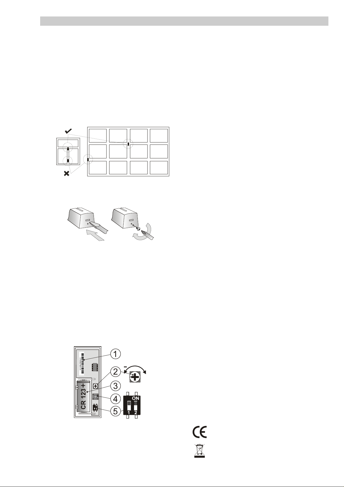
Fig. 3 1 – serial number; 2 – swiv el trimmer for adjusting sensitivity; 3 -
CR-123 battery; 4 – tamper contact; 5 – configuration switch
The detector always transmits a DEL (delayed) reaction. If a different
reaction is required in the Jablotron system, it can be set in the control panel.
The SHOCK / TILT (DIP2) switch selects the detector function. When the
switch is in SHOCK (DIP2 off) position, the detector works in shock mode; tilt
detection mode is selected by switching it to the TILT position (DIP2 on).
JA-182SH wireless shock and tilt detektor 1/1 MLB51501
Can be operated according to ERC REC 70-03
JABLOTRON ALARMS. hereby declares that the JA-182SH
is in compliance with the essential requirements and other
relevant provisions of Directive 1999/5/EC. The original of the
conformity assessment can be found at www.jablotron.com,
Technical Support section
Note: Although this product does not contain any harmful
materials we suggest you return the produc t to the dealer or
directly to the producer after use.
 Loading...