

Page 1
The JA-114E Bus access module with LCD, keypad and RFID
The JA-114E Bus access module with LCD, keypad and RFID MLU51105
The keypad is a component of the JABLOTRON JA-100 system. Its
modular architecture enables users to create a combination whose size
of installation perfectly meets their needs. The device should be
installed by a trained technician with a valid certificate issued by
authorized distributor.
The keypad comprises a display, an RFID card / chip reader and the
first control segment (1). JA-192E segments can be used to extend the
JA-114E unit by the required number of segments (the max. allowed
amount is 20 on one unit). The tilting keypad cover (6) can be removed
if the user prefers permanent access.
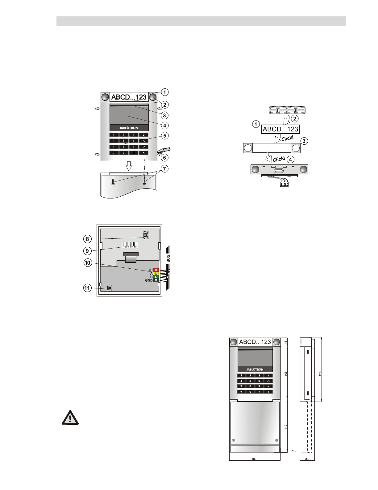
Figure: 1 – control segment; 2 – segment buttons; 3 – backlit activation
button; 4 – LCD; 5 – keypad module with RFID; 6 – tabs for opening;
7 - cover screws
Figure: 8 – control segment connector; 9 – production code;
10 – bus terminals; 11 – tamper contact
Installation
1. Gradually press the four tabs (6) on the sides and release the
keypad from the plastic base.
2. When installing more control segments, first remove the socket
cover on the 1st segment.
3. Remove the plastic windows from the segments (by levering on
both sides of the segments near the buttons).
4. Always connect the segment wires to the connector of the previous
segment and click them into each other (we recommend coiling the
wires by turning the segment by 360° – this will prevent any
possible damage to the wires between the plastic parts). Use this
method to install all the required control segments. Finally, push the
socket cover in.
5. Push the cable through the plastic base and attach it to the
selected place together with the segments using screws. If
multiple control segments are required, attach them onto the wall
using screws as well (use the number of screws required).
6. Connect the bus cable to the bus terminals (10).
When connecting the module to the bus,
always switch the power off.
7. Connect the segment wires to the internal connector of the keypad
(8).
8. Insert the keypad into the base.
9. Proceed according to the control panel installation manual. Basic
procedure:
a. When the device is switched on, the yellow LED starts flashing
repeatedly to indicate that the keypad has not been enrolled
into the system.
b. Go to the F-Link program, select the required position in the
Devices window and launch the enrollment mode by clicking
on the Enroll option.
c. Press the backlit activation button (3) above the screen – the
keypad is thus enrolled and the yellow LED indicator goes off.
10. When you have completed the installation, insert descriptive labels
onto the segment plastic windows and close them. Label printing is
a part of the F-Link program (Devices window, at the keypad
position – Internal settings).
Note: To comply with the EN 50131-3 norm it is necessary to fix the
cover tab by the screws from the accessories. In picture no 1 the
cover tabs are fixed by the arrows.
Figure: Inserting a label into a control segment
Setting the properties
Go to the Devices window in the F-Link program. When you are at
the keypad position, use the Internal settings option. The particular
unit is displayed and it is possible to set its properties. It is possible to
set the required functions for individual segments (control of sections,
section status signalling, alarm triggering, PG output control, PG output
status signalling, etc.). More details are available in the F-Link program.
A common segment (up to 2 of them allowed on one keyboard) simulates
the simultaneous pressing of several segments which are placed on this
keyboard and which control sections. The selection of sections which are
assigned to the common segment is performed by F-Link SW, the Devices
window. At the keyboard position select Internal settings / and Common
segment 1 (2) and mark the segments which will be operated en bloc. The
selected sections will be set / unset after pressing a button on the common
segment. If the states of the segments which are operated by the common
segment are mixed, then only the segments that need changing will be set /
unset. If partial setting is enabled for some segments, then the common
segment respects this: 1 st. press = partially setting, 2nd press = full setting. It
is not suitable to combine a common segment with a common section
The indication of the common segment is: all segments set = green, some
set (partially set) = yellow, all sections fully set = red.
Unit modifications
If you need to change the unit’s individual segments, it is possible to
separate them by levering the corresponding separating gaps from one
side (sideways from the buttons).
Page 2

The JA-114E Bus access module with LCD, keypad and RFID
The JA-114E Bus access module with LCD, keypad and RFID MLU51105
Technical specifications
Power from control panel digital bus (9…15 V)
Current consumption in standby mode 15 mA
Current consumption for cable selection 50 mA
Each additional control segment 0.5mA
RFID frequency 125 kHz
Operating temperature range -10 to +40 °C
Operational environment according to EN 50131-1 II. Indoor general
Classification Grade 2
according to ETSI EN 300330, EN 50131-1, EN 50131-3,
Also complies with EN 50130-4, EN 55022, EN 60950-1
Can be operated according to ERC REC 70-03
JABLOTRON ALARMS a.s. hereby declares that the JA-114E module is in
compliance with the essential requirements and other relevant provisions of
Directive 1999/5/EC. The original of the conformity assessment can be found
at www.jablotron.com - Technical Support section
Note: Although this product does not contain any harmful materials we
suggest you return the product to the dealer or directly to the producer
after use. For more detailed information visit www.jablotron.com.
 Loading...