

Page 1
JA-111ST Bus combined smoke and heat detector
{
The JA-111ST is a component of the JABLOTRON JA-100 alarm
system. It is used to detect fire hazards in the interior of residential or
commercial buildings. The product is not designed to be installed in
industrial premises. The detector is powered via the control panel digital
bus (EN 54-7; EN 54-5). When the detector is used with inserted
batteries (3x 1.5 V AA) from which it can be powered, it can continue
operating as a stand-alone detector when the 12 V power supply
is disconnected (EN 14604).
The detector indicates fire hazard using the built-in LED indicator and
acoustic signalling.
The JA-111ST consists of two independent detectors – an optical
smoke detector and a heat detector. The optical smoke detector works
on the principle of scattered light. It is very sensitive to large dust
particles which are present in dense smoke. It is less sensitive
to smaller particles generated by the combustion of liquids such
as alcohol. That is why the fire detector also contains a built-in heat detector
which has a slower reaction but is much better at detecting fire which
generates only a small amount of smoke.
Detector range and location
The smoke detector must be installed so that any smoke easily drifts
into the detector owing to natural thermal currents, e.g. on the ceiling. It is
suitable for residential buildings but not suitable for free spaces, outdoor
environments or interiors with extremely high ceilings (above 5 m)
where fire by-products can disperse over a large area – the smoke
would not reach the detector position.
The detectors should be installed by a trained technician with a valid
manufacturer’s certificate.
Detectors should be installed in the building according to the project
documentation. If such documentation is not available, their position
should comply with the effective standards for fire alarm signalling
systems.
The detector must always be placed in the section leading to the exit
of the building (escape route), see Fig. 1. If the building has a floor area
greater than 150 m
suitable place is required, see Fig.2.
2
, installation of an additional detector in some other
Fig 1
1. kitchen,
2. living room,
3. – 6. bedrooms
y / basic coverage
Fig 2
/ recommended coverage
0,9 m
Fig 1
Fig 2
centre of the room, best location
acceptable location
Walls, partitions, barriers and lattice ceilings
The JA-111ST detector must not be installed closer than 0.5 m
from any wall or partition. A narrow room with a width of less than 1.2 m
requires the detector(s) to be placed at a distance of at least one third of the
room’s width away. In a case when a room is separated into sections with
walls, semi partition walls or furniture which do not reach the ceiling, the
space is considered as a fully separated if the gap between the top of
these and the ceiling does not exceed 0.3 m are performed as a single
rooms. A free space of at least 0.5 m is required under and around the
detector. Any irregularities of the ceiling (e.g. girders) exceeding 5 % of the
ceiling height should be considered a wall and the above mentioned limitations
should apply.
Ventilation and air circulation
The detectors must not be installed directly by ventilation or air
conditioning vents. In the case of air being supplied through a
perforated ceiling, each detector must be placed so that no perforation
hole occurs within 0.6 m of the detector.
Avoid installing the detector in the following locations:
x places with poor air circulation (niches, corners, apexes of
A-shaped roofs, etc.)
x places exposed to dust, cigarette smoke or steam
x places with over-intense air circulation (close to ventilators, heat
sources, air conditioning outlets, etc.)
x in kitchens and other cooking places (because steam, smoke or oily
fumes can cause false alarms or reduce detector sensitivity).
x beside fluorescent lights or energy-saving light bulbs (electrical
interference can cause a false alarm)
x in areas with lots of small insects
Warning: Most false alarms are caused by improper detector
location.
See CEN/TS 54-14 standards for detailed installation guidelines.
Installation
When installing the detector, abide by the procedures recommended
in the previous paragraphs.
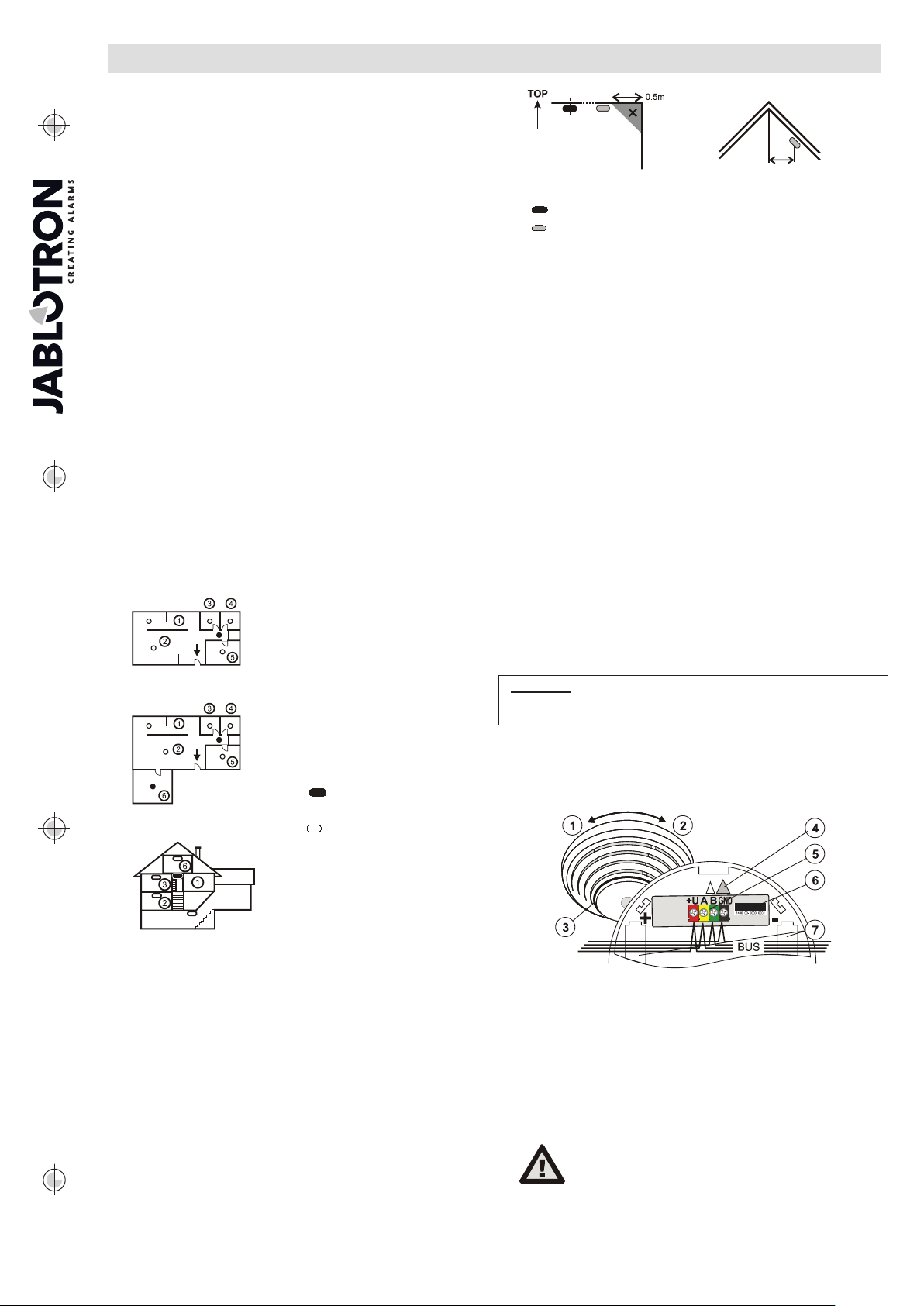
Fig 3
In multi-storey flats and family houses the detector should be
installed above the stairs. It is recommended to place additional
||
JABLOTRON ALARMS a.s.
Pod Skalkou 4567/33 46601 Jablonec n. Nisou
detectors in rooms where people sleep. See Fig 3.
Installation on level ceilings
|
Czech Republic www.jablotron.com
Place the detector in the centre of the room if possible. The detector
must not be recessed into the ceiling due to the possible existence
of a cool air layer on the ceiling. Never place the detector in the
corner of the room (always keep at least 0.5 m distance from the
corner - see Fig 4). There is an insufficient circulation of air in the
corners.
Installation on sloping ceilings
If the ceiling is not suitable for mounting on a level surface (e.g. a
room under a roof ridge), the detector can be installed as in Fig. 5.
Fig 3: 1 – detector cover opening; 2 – detector cover closing;
3 – optical status signalling; 4 – arrow showing where to insert the detector;
5 – bus terminal; 6 – production code; 7 – battery holders
1. Open the detector cover, by turning it anti-clockwise (1)
2. Push the bus cable through the base and attach the base to the
selected place using screws.
3. Connect the bus cable.
4. When the device is switched on, the yellow LED on the PCB
inside the detector starts flashing repeatedly to indicate that
the detector has not been enrolled into the system.
When connecting the detector to the
system digital bus, always switch the
power off.
JA-111ST Bus combined smoke and heat detector 1 / 2 MLW55307
Page 2

JA-111ST Bus combined smoke and heat detector
Proceed according to the control panel installation manual.
Basic procedure:
a. Go to the F-Link program, select the required position in the
Detectors window and launch enrollment mode by clicking on the
Enroll option.
b. Insert the detector into the plastic base. The detector can be
inserted in the base in one position only. It is marked with arrows
(4). Close the detector by turning it clockwise (2). The tamper
contact inside the detector is thus triggered and the detector is
enrolled. The yellow LED indicator goes off. When inserting the
detector, bear in mind that the connecting wires must not restrain
the functioning of the testing buttons.
Warning:
batteries are inserted! (only if EN 14604 compliance is required).
The mounting base must not be replaced by bases meant for
detectors without the test button consisting of pressing the body
of the detector.
Note: The detector can also be enrolled into the system by entering
its production code (5) in the F-Link program (or using a bar code
scanner). All numbers stated under the bar code shall be entered
(1400-00-0000-0001).
Detector insertion into the base is blocked unless all 3
Detector setting
The detector properties can be set in the Detectors window in the
F-Link program:
The Reaction option in the Detectors window allows you to set the
type of system reaction to the activation of the enrolled detector.
To set the detector properties use the internal settings access
button. This opens a window where can be set internal setting and
behavior of the detector.
Alarm memory in the stand-alone mode determines whether the
detector will indicate alarm memory with a LED indicator even when the
detector is in a stand-alone mode.
Reaction enables setting which impulses the detector should react to:
Smoke EN 14604, EN 54-7
Temperature EN 54-5
Smoke or temperature EN 14604, EN 54-5
Smoke and temperature at once
Acoustic signalling sets the time for which the detector keeps
chirping (applies in the system detector mode only). When in the standalone mode, the detector keeps chirping for the whole duration of the
alarm (smoke in the room or high temperature). The chirping can be
terminated by pressing the detector against the base.
Batteryless operation. When this parameter is set, the detector
works only as a control panel-powered system detector and the low
battery detection is disabled.
When batteryless detector operation is required (EN 54-x), the
blocking mechanisms preventing insertion of the detector without
inserted batteries should be removed.
EN 54-7
The detector does not comply with EN 14604 with this
setting.
Thermal class EN54-5 determines the reaction speed of the
detector to temperature increases.
A1 – A fast reaction to temperature changes. It has to react within
1 min 40 sec when the temperature reaches 30 °C/s.
A2 – A slow reaction to temperature changes. It has to react within
2 min 25 sec when the temperature reaches 30 °C/s. These
detector settings have a high immunity to false alarms in
problematical installations.
Fire alarm
Fire alarm is signalled both acoustically and optically.
When the conditions for fire alarm triggering are met (smoke is
detected in the room, the alarm temperature is reached, or both
conditions are met), the detector signals the danger by sounding the
siren and quickly flashing of the LED indicator (3). The alarm
information is concurrently sent to the system control panel.
Silencing the siren during an alarm: The siren can be silenced by
pressing the detector body against the base. The siren is inactive for 10
minutes. If the detector still detects smoke or heat after this time, the
siren is activated again.
When the need arises (e.g. in the case of a detector failure), it is
possible to postpone siren reactivation by up to 12 hours. This can be
done by pressing the detector again for 5 s after silencing the siren.
When the detector chirps, you have to release the pressure within 1 s.
The switchover to the postponed siren mode is confirmed with 5 chirps.
The detector LED flashes all the time during the postponement.
Alarm memory: LED indication continues flashing slowly even when
the smoke clears or when the temperature decreases. The indication
lasts 24 hours unless it is terminated by pressing the detector body.
Tamper alarm: When the detector cover is opened, the detector
sends a tamper signal to the control panel.
Detector testing and maintenance
The detector should be tested at least once per month. To test the
detector press the detectors body against the base and wait until a LED
indicator switches on. The LED flashing signals switchover to the testing
mode . The LED is flashes for the wh ole duration of the test. When the
test is complete, the LED switches off. The detector then signals the result. If
the detector beeps once, the test has been done successfully. If a
failure is discovered, the LED flashes and beeps three times. If the
battery is low, there is no acoustic signalling but just one flash when the
test is completed.
The complete functioning of the optical part of the detector can be
tested with a testing spray (e.g. SD-TESTER). The heat sensor can be
tested with heated air (e.g. with a hair dryer). If the control panel is not
in the SERVICE mode, a fire alarm is triggered.
Warning: never test the detector with fire.
Fault indication
The detector checks its functioning. If it discovers a fault, it chirps and
flashes the LED three times and then flashes shortly three times every
30 s.
A detector test can be carried out when a fault is signalled, see paragraph
Detector testing and maintenance. When the detector is fixed the detector
beeps once briefly.
If you have not managed to fix the fault, the detector must be sent to a
service centre.
Battery replacement
The detector checks the battery status if used and if the batteries are
running low, the detector signals that they need replacing by short
flashes repeated every 30 s. The information is also sent to the control
panel. Replace the batteries as soon as possible. Always replace all
three batteries of the same type and manufacturer.
Use only high-quality 1.5 V AA alkaline batteries.
Do not throw used batteries into ordinary household waste.
Deposit of them at authorized collection points.
Removal of the detector from the system
The system reports any possible detector loss. If you have removed it
on purpose, you also have to erase it from the correspondent address in
the control panel memory.
Technical specifications
Power 9 – 15 V DC/3.5 mA (150 mA during an alarm)
Typical lifetime approx. 3 years
Smoke detection optical light scattering
Smoke detector sensitivity m = 0,11
Heat detection class A1 according to EN 54-5
Alarm temperature + 60 °C to +65 °C
Operating temperature range -10 °C to +65 °C
Dimensions, weight diameter 126 mm, height 52 mm, 150 g
Conformity EN 50130-4, EN 55022
14
1293
JABLOTRON ALARMS a.s. hereby declares that the JA-111ST
is in a compliance with the relevant Union harm onisation legislation:
Directives No:
conformity assessment can be found at www.jablotron.com Section Downloads.
Note: Although this product does not contain any harmful
materials we suggest you return the product to the dealer
or directly to the producer after use.
3 pcs of alkaline batteries type LR6 (AA) 1.5 V
Please note: Batteries are not included
y
pursuant to EN 14604, EN 54-7
0,13 dB/m
1293-CPR-0396
2014/30/EU, 2011/65/EU. The original of the
JA-111ST Bus combined smoke and heat detector 2 / 2 MLW55307
 Loading...