

Page 1

Security Alarm Control Panel
HESTIA-915
installation manual
Page 2
Description:
The Hestia-915 is the next generation in versatile wire operated alarm systems. The control panel provides eight
protection zones: FIRE, TAMPER and six programmable loops. All loops are balanced with End Of Line resistors. Most
control panel functions are programmable, resulting is a very flexible system. Control panel is offered in different housing
options (H-915C - plastic housing with built in keypad & display, H-915M - metal housing, H-915P - plastic housing
without keypad & display, H-915B - only main board, H-915K - external keypad).
An assortment of optional devices can be connected to the control panel (detectors, external keypads, remote controls,
telephone dialers, etc.). Refer to your Jablotron catalog for more details, or contact your local Jablotron dealer. Please
note that Jablotron strongly recommends professional installation of this system.
SPECIFICATIONS:
power:
transformer required: 15VAC/20VA or DE-20-15
backup battery required: 12V, from 1.2Ah to 40Ah
stand-by consumption: 25mA
back-up power output: 12V, max. 500mA
inputs:
eight loops: FIRE, TAMPER and 6 fully programmable loops
type of loops: balanced with End Of Line resistor 10k
remote control inputs: digital bus for external keypads, programmable optional pulse input
outputs:
overswitching relay contact: 1A at 60 V
external siren output: 0.5A at 12 V
backup siren output: +BS
fire alarm output: 0.2A to GND
arm output: 0.2A to GND
panic output: 0.2A to GND
internal siren: 0.2A to GND (H-915C built-in)
codes:
Master code, five user codes, panic code, One Time Use code and installer code: all codes are four digits. All codes
and settings are stored in non-voltage memory
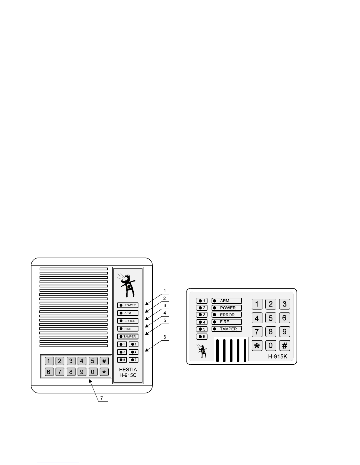
FRONT PANEL
(The following description is for the control panel of the H-915C as well as for the front panel of the external keypad
model H-915K)
Display:
1 POWER - (Green LED) continuously lit indicates that the power supply is properly functioning . A blinking led means
that the system is powered only by the back up battery. If this LED is off, the system has no A.C. power and the back-up
battery is discharged.
H-915 installation manual 11/2 TBT502 01
Page 3

H-915 installation manual 11/3 TBT502 01
2 ARM - (Yellow, Green and Red LEDs) if this LED is off, the system is disarmed. If it is yellow and slowly blinking, it
indicates an Exit delay. A continuously lit yellow LED indicates that the system is fully armed. A Rapidly blinking yellow
LED indicates an Entrance delay.
A Slow blinking green LED indicates an Exit delay for the AT HOME arming (only if AUTO AT HOME function enabled). A
continues green light indicates that system is AT HOME armed. A rapidly blinking green LED indicates an Entrance delay
for AT HOME arming.
A red blinking means an alarm condition on the control panel (PANIC alarm is not indicated).
3 ERROR - (Red LED) continuously lit indicates system is in the programming mode. Slow blinking indicates either
a power supply failure or memory of a Technical alarm. Rapidly blinking confirms programming of bypass.
4,5,6 ZONE STATUS LEDs: FIRE, TAMPER, 1 to 6: When on in the normal operating mode, a lit LED indicates
a triggered input. Slow blinking zone LED means alarm memory information. It can be reset by rearming or entering
[∗][3].
Rapidly blinking zone LED during exit delay indicates if a zone has been bypassed.
7 Keypad: All control panel functions can be controlled by or programmed with the keypad. Pressing the [#] key
erases the input buffer (stops the programming) and acts as an ESC function. The input buffer can also be erased if an
incorrect or incomplete entry is made (after 20 seconds).
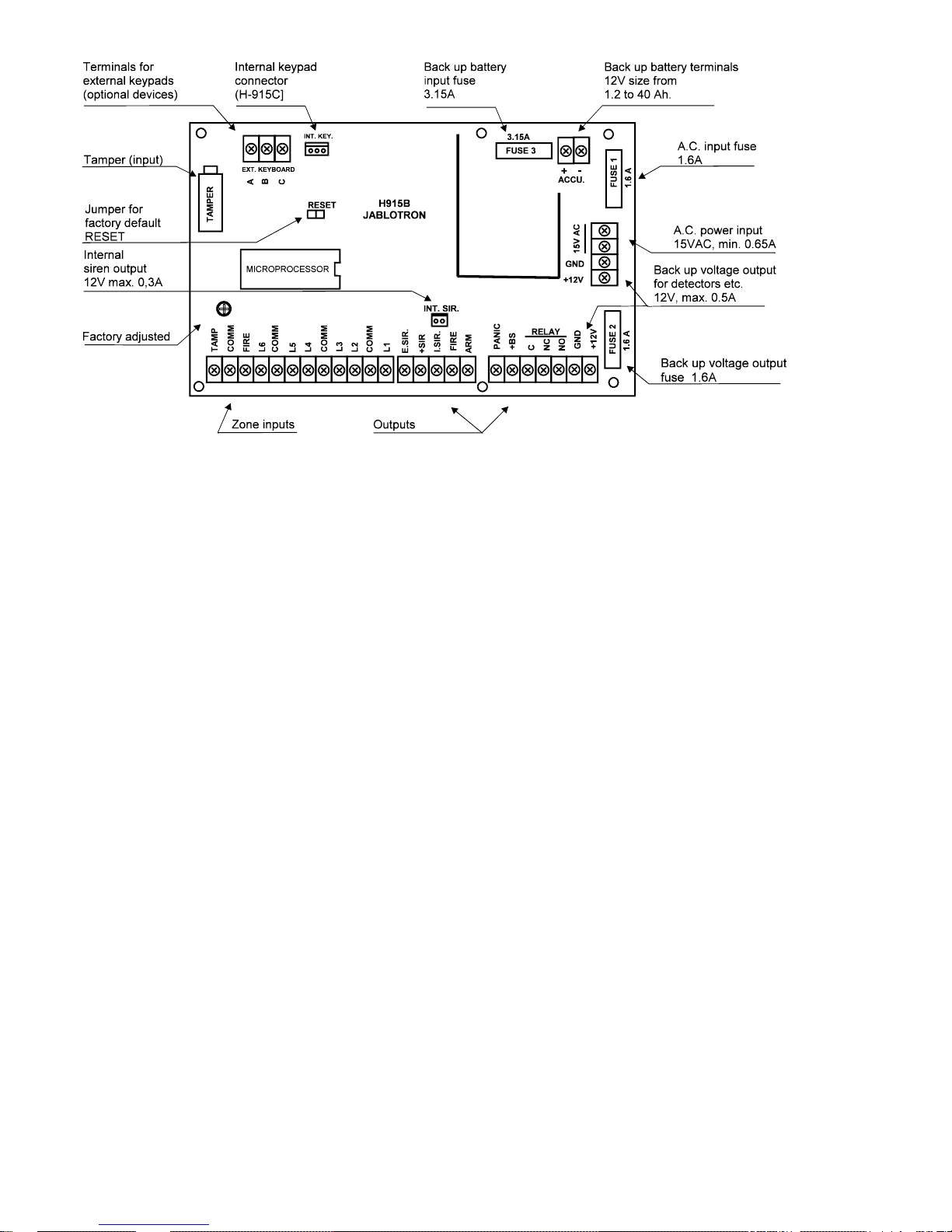
WIRING
Zone inputs:
TAMP, FIRE, L1 to L6 and COMM terminals All zone inputs are supervised End Of Line (EOL) resistor circuits. Each
input must be terminated with a 10K ohm EOL resistor to any of the COMM terminals. An input will be triggered if a
normally open contact is used to short across the EOL resistor. An input is also triggered if normally closed contacts
wired in series with EOL resistor are opened (see the wiring diagram).
The Fire alarm is activated if a detector connected to a FIRE input is triggered. The Tamper alarm can be triggered
either by the built in tamper switch (control panel & keypads) or by the tamper switches connected to the TAMP input.
The definition of zone 1 to 6 (delay, instant, 24hr., fire etc.) can be programmed from the keypad using the [∗] [6]
installer programming mode.
NOTE: None of the COMM terminals can be connected to the GND or any other control panel terminal. Such
a connection will trigger all zone inputs.
Outputs:
E.SIR terminal is for connection of the external siren (use pi ezo siren SA-105 or SA-107). The function of this output is
programmable for different alarm types (using the [∗] [6] installer programming mode). This output is switched to GND
with a NPN switching transistor when activated. Maximum load can be 500mA.
+SIR terminal is the backup +12V power output for sirens (external and internal), max. 1A (built in fuse FU4).
The following four output terminals are closed to the GND with a NPN switching transistor when activated. Maximum
load of each output is 200mA. A 10 ohm current limiting resistor is connected in series with the switching transistor.
A small relay, buzzer, siren or other DC operated device may be connected between the +12V terminal and each of the
above output terminals.
I.SIR terminal is the output for the internal siren (use piezo siren SA-105 or SA-107). The function of this output is
programmable for different alarm types (using the [∗] [6] installer programming mode). Model H-915C has built in internal
sirens connected via a connector.
FIRE output is active for alarm period if alarm is triggered by a fire input(s).
ARM output is active while the control panel is armed (no matter if in FULL arming or AT HOME arming position).
PANIC output is active for alarm period if the PANIC or any silent alarm loop is triggered.
Page 4
+BS - this terminal is for connection with an outdoor back up siren. There is a positive potential supplied by this terminal
when the alarm output relay is not switched on.
C, NC and NO terminals are over switching dry contacts for alarm output relay. The maximum load is 1A/60V. The
function of this relay is programmable for different alarm types (using the [∗] [6] installer programming mode).
Power:
+12V, GND - back up voltage output for optional devices (motion detectors, telephone dialers etc.). There are two pairs
of these terminals on the board, both of them are connected together. Maximum current consumption can be 500mA all
together. The +12V output is protected by a FU2 (1.6A) fuse.
15VAC - these terminals are for A.C. power supply connection. Use a transformer with 15VAC output (min. 20VA), or you
can use the Jablotron PSU-10 adapter. This input is protected by a FU1 (1.6A) fuse. Do not switch the power on before
the installation is finished!
ACCU. - these terminals (+/-) are ready to connect to a back-up battery 12V. Size from 1.2Ah to 40Ah can be used. In
normal operating mode the control panel charges the battery. Battery input is protected by a FU3 (3.15A) fuse. Do not
connect the battery before the installation is finished!
Keypad: There are three EXT.KEYBOARD terminals to connect to external keypads model H-915K (or other optional
H-915 device with serial communication). Use three wires to connect the A,B and C control panel terminals with
corresponding A,B and C terminals in the keypad. The maximum length of keypad cable should not exceed 50 meters. If
you use multiple keypads (a maximum of 5 can be used) connect all of them in parallel. Check carefully that you have
connected corresponding wires before you turn on the power to the control panel. (The built-in keypad on the H-915C
model is connected via INT.KEY connector.)
Control panel TAMPER: There is a tamper switch to protect the housing of the control panel. If you have only the
H-915B (main board) don't forget to install the attached tamper switch in the housing.
Procedure for Turning on the Power:
Make a short connection of the RESET link on the board with a jumper. Connect the back up battery and A.C. power
supply. Wait 2 seconds and remove the reset jumper. Close the housing of the control panel (connect front panel - only
model H-915C).
The control panel will reset to the factory default settings automatically and then will perform a self test. When finished, it
will be in the installer programming mode. (Press [#] to enter standby).
Operation
There are three levels of operation in the H-915: STANDBY, USER PROGRAMMING and INSTALLER
PROGRAMMING.
The STANDBY mode is the basic working mode of the control panel. It is ready for arming control. The system can be
directed to perform other functions such as zone bypassing, displaying alarm memory and entering programming level by
using one of the various [∗] commands described below. In STANDBY mode, the zone lights indicate the triggering of
zones, or alarm memory with a slow blinking..
MASTER CODE
A default master code 1234 is programmed into the H-915 at the factory. The master code is used for arming control as
other access codes, but only the master code can be used for entering the user programming level ([∗] [5] command) and
for bypassing zones ([∗] [8] command).
The master code can be reprogrammed by the user, but it can not be removed.
H-915 installation manual 11/4 TBT502 01
Page 5

H-915 installation manual 11/5 TBT502 01
INSTALLER CODE
A default installer code 1010 is programmed into the H-915. This code is used with the [∗] [6] command to enter the
installer programming level. This code can be changed by installer.
ARMING
Enter a valid access code to arm. Arming is confirmed by the ARM LED and with one beep from the keypad's buzzer.
The system can not be armed if any zone is triggered. If you enter [∗][9] before the access code, the system will be AT
HOME armed (the interior zones will be bypassed automatically).
The system can also be armed by entering only [∗][0] if the quick arming function was enabled in the installer
programming level. If quick arming is enabled, the H-915 can be AT HOME armed by entering only the [∗] [9] command.
DISARMING
Enter a valid access code to disarm. If the "chime" jumper in the H-915K keypad is connected and you triggered
a sensor in a delay zone, the keypad buzzer will be beeping. In such a case you have only a limited amount of time
(entrance delay) to enter a valid access code. If an error is made in entering the code, press the [#] key and enter the
code again. The ARM LED will go out and keypad's buzzer confirms disarming with two beeps. If there are three beeps
as confirmation, it means that there is important information on display for you (for example alarm memory).
If an alarm is triggered while you are present and you want to stop it, enter a valid access code.
Page 6

H-915 installation manual 11/6 TBT502 01
[∗] COMMANDS LIST
All the commands bellow can be used only when the control panel is in the standby mode and is disarmed.
[∗] [0] - Quick arming
. You can use this command instead of your access code to arm the system. It can be
used only for arming, not for disarming. This command works only if quick arming enabled in installer programming level,
section 4.
[∗] [1] - Alarm memory display
. You can recall the information about the last alarm with this command.
A blinking zone LED shows which zone triggered the last alarm. To switch the display back to normal operation, press
[∗][3] or rearm the system.
[∗] [3] - Switching OFF the alarm memory display
. The display switches back to normal operation.
[∗] [5] [MASTER CODE] - Entering of USER PROGRAMMING LEVEL
(factory default master
code is 1234). Eight different codes (from code 0 to 7) can be programmed in this level: new master code (0), up to five
access arm-disarm codes (1 - 5), a PANIC code (6) and a "One Time Use" code (7) may be programmed. Entering of the
programming level is confirmed by eight short beeps and the ERROR LED being permanently lit.
Press [#] to exit the programming level. Remember, if no keypad entry is made for more than 1 minute, the system
will return to the standby mode automatically.
Programming new codes:
1/ Enter user programming level pressing [∗] [5] [MASTER CODE]
2/ To change master code, press [0] (confirmed with short and long beeps) then enter new 4 digit code (confirmed with
two short beeps if entered correctly). Master code can be only changed, it can not be erased
3/ To program access code number one, press [1] (confirmed with short and long beeps) and enter 4 digit code
(confirmed with two short beeps if entered correctly).
4/ To remove access code number one, press [1] [∗]
5/ Follow instructions in 3/ or 4/ for programming or removing any of other access codes from 1 to 5
6/ You can program the PANIC code as code number six. This code can also be used for disarming, but it triggers a
silent panic alarm every time it is used. This feature can be very useful in the case you are forced to operate the alarm
system under pressure. Follow instructions in 3/ or 4/ for panic code setting or removing if you do not want this function.
7/ The code number seven works as "One Time Use" code if programmed. Follow instructions in 3/ or 4/ for its
programming or removing. The "One Time Use" code can be used for arming/disarming control, but this code is
removed automatically in the moment when used once for arming.
NOTE: If you press [9] in user programming level the H-915 control panel will send information about events history to
the special serial interface (printer) which can be connected to the keypad terminals as an option.
Only code number 0 - master code is programmed from factory, the other access codes are bl ank.
[∗] [6] [INSTALLER CODE] - Entering of INSTALLER PROGRAMMING LEVEL
. The
control panel H-915 is completely programmable from the keypad by using commands which are described in detail in
the installer programming section of this manual.
[∗] [8] [MASTER CODE] - Entering of zone 1 to 6 bypassing
. A bypassed zone will not cause an
alarm. If a zone is bypassed, the panel may be armed even if the zone is triggered. Use bypassing when access is
needed to part of the protected area. Also damaged wiring or contacts on a zone may be temporarily bypassed until
repairs can be made. To bypass zones, enter [∗] [8] [MASTER CODE] and the zone number(s) to be bypassed. Press
[#] to return back to standby mode. Remember, if no keypad entry is made for more than 1 minute the system will
return to the standby mode automatically. The ERROR LED will blink rapidly while you are in zone bypassing mode.
The zone LEDs which are blinking, while bypassing is selected, indicate the bypassed zones. By pressing a number key
(from 1 to 6) you can "switch ON - OFF - ON ..." the bypass of the corresponding zone. When you are arming the H-915
and bypass of any zone(s) is set, you will see the corresponding zone LEDs blinking during exit delay. This way, the
keypad informs you of which zone(s) were switched off. The Bypass setting is only valid for one arming period. Zone
bypasses are automatically canceled when the panel is disarmed.
[∗] [9] [access code] - AT HOME arming
. Entering [∗] [9] before the arming code arms the panel without
any exit delay in the delay zones and bypass zones that are defined as "INTERIOR". When the panel is AT HOME
armed, the color of the ARM LED light is green.
NOTE: If quick arming feature was enabled in the installer programming level, press only [
∗
] [9] for AT HOME arming.
AUTO AT HOME ARMING
- if this function is enabled in the installer programming level (section [4]), the system is
able to recognize automatically if you are at home or not.
If a correct access code is entered for arming, the green ARM LED will flash slowly. The system expects that you will
stay at home and it is ready for AT HOME arming after the exit delay. If you trigger a delay zone during the exit delay (for
example with magnetic sensor on the entrance door), the light of the ARM LED turns yellow and the system will be fully
armed.
Page 7

H-915 installation manual 11/7 TBT502 01
INSTALLER PROGRAMMING
Press [∗] [6] [INSTALLER CODE] to enter installer programming level (factory default installer code is 1010). It can
only be done while the panel is disarmed. Entering the programming level is confirmed by the ERROR LED permanently
lighting.
While in this level, no zone can trigger an alarm in. The zone LEDs indicate the zone status, so the programming level
can also be used for testing and servicing of the alarm system. The [#] must be pressed to exit the programming
level (there is no time supervision in this level).
The next step in the installer programming level is to enter a 1 digit section entry for any of the commands described in
the following text. As soon as the section digit is entered, the keypad will make a short and long beep for confirmation.
The keypad is now ready to accept data entry for the selected section. The keypad will beep twice shortly if the data is
entered correctly. After completing one section, you can program other sections or you can return to standby by pressing
the [#] key.
All the settings are stored in the non voltage memory. A programming work sheet summarizing all programming
commands is provided in the next section of the manual. Fill out the work sheet and use it as a guide when programming.
PROGRAMMING SECTIONS LIST:
[0] [xxxx] - New INSTALLER CODE
(xxxx = 4 digits code)
Example: enter [0] [6789] to set new installer code 6789
[1] [xyy] - Zone definition for zones 1 to 6
. Once this section is entered, a 3 digit number is required.
The first digit (x) determines the zone number 1 to 6
The second and third digits (yy) determine the zone type 00 to 13 as described below:
[00] = OFF can be used to switch the corresponding zone input completely off.
[01] = 24Hr.loop is active at all times and will result in an intruder alarm if the panel is armed or disarmed.
Note: The TAMPER loop in the H-915 is firmly programmed as a 24Hr. loop.
[02] = Instant loop is normally used for all kinds of intruder detectors. This loop can trigger an intruder alarm only if the
panel is armed.
[03] = The Delay loop has an entry and exit delay and is normally used for entry/exit doors. The exit delay starts as soon
as the panel is armed. The loop may be triggered during the delay time without resulting in an alarm. After the exit delay
time has expired, triggering the loop will start the entry delay timer. During the entry delay time the system must be
disarmed in order to prevent an intruder alarm. The default times are 20 seconds for entry delay and 40 seconds for exit
delay. These times can be programmed in section [2].
[04] = Next delay loop is normally used with interior motion detectors and has an exit delay. The loop also has an entry
delay time provided that a delay loop has first been triggered . If the premises is entered without coming through a "delay"
entrance and a next delay loop is triggered, an immediate intruder alarm will be generated.
[05] = 24Hr. silent loop operates as the type [01], but it triggers the PANIC alarm.
[06] = Instant silent loop operates as the type [02], but it triggers the PANIC alarm.
[07] = Delay silent loop operates as the type [03], but it triggers the PANIC alarm.
[08] = Interior instant loop operates the same as the type [02] loop. But if the panel is AT HOME armed, this loop is
bypassed. This type of loop is normally used with interior motion detectors in the living section of the house.
[09] = Next delay interior loop operates the same as the type [04] loop. But if the panel is AT HOME armed, this loop is
bypassed. This type of loop is suitable for motion detectors which cover an area the keypad is located in.
[10] = Fire is active at all times and will create a fire alarm if the panel is armed or disarmed.
Note: There is one firmly programmed FIRE loop in the H-915 control panel.
[11] = 24Hr. delay silent loop operates the same as the type [05], but it provides an Entry delay between the input
triggering and the PANIC alarm starting. This type of loop is suitable for panic buttons, which can be triggered
accidentally. In such a case, the user has a chance to avoid the alarm if he/she chooses.
[12] = Warning 24Hr loop is a variation of the 24Hr. loop. It can not trigger any alarm, but it can send information to the
serial communication line (keypad terminals) no matter if armed or disarmed. For optional future use.
[13] = Warning instant loop is a variation of instant loop which can not trigger any alarm, but it can send information to
the serial communication line (keypad terminals) if armed. For optional future use.
Note: Loop number 6 can also be used for external arming control, see section [4]. If this function is enabled, the 6th loop
will not work as a zone input.
Examples: Enter [1][304] to program zone number 3 as next delay loop, enter [1][503] to program zone number 5 as
delay loop,...
[2] [xms] System times
- once the section is entered, a three digit number is expected to be entered.
The first digit (x) determine type of time (0=entry delay, 1=exit delay, 2=alarm duration). Only a 0,1 or 2 selection will be
accepted. The second digit (m) represents minutes and can be from 0 to 9. The third digit (s) represents time in
seconds x10. It can be from 0 to 5 (5 = 50 seconds).
Note: If you set m=0 & s=0, the corresponding time will be 5 seconds - it can be used for testing.
Examples: Enter [2] [103] to adjust the exit delay to 30 seconds, enter [2] [010] to adjust entry delay to 1 minute, enter [2]
[253] to adjust the alarm duration to 5 and half minutes.
[3] [xy] Alarm outputs definition
- once this section is entered, two digits are required.
The first digit (x) determines the type of alarm (technical, fire, intruder, panic). The second digit (y) determines which
programmable control panel output will be activated (external siren, relay, internal siren).
The control panel has four different alarms:
Page 8

H-915 installation manual 11/8 TBT502 01
x=0 Technical alarm - results when the a.c. power is off for a long time and the backup battery is nearly discharged. Any
combination of outputs can be selected for this kind of alarm (y can be from 0 to 7)
x=1 Fire alarm - triggered by a fire loop. This alarm always activates the FIRE output. But it can also activate any
combination of other outputs (y can be from 0 to 7)
x=2 Intruder alarm - is triggered by any intruder zone (see zone definition) or if a predetermined number of attempts to
enter a valid access code is reached . Any combination of outputs can be selected for this kind of alarm (y can be from 0
to 7).
x=3 Panic alarm - is triggered by the panic code, by any silent loop (24Hr. silent loop, 24Hr. delay silent loop etc). This
alarm always activates the PANIC output. It can also activate a relay output if necessary. The "y" can only be 0 (panic
output only) or 2 (panic output and relay output).
There are three programmable alarm outputs in the control panel:
External Siren (E.S), Relay, Internal Siren (I.S.). Consider, that +BS output works the same way as a relay output.
Therefore, if the relay is activated, the +BS output is activated as well. See the following table to set requested
combination of output's reaction:
y E.S. Relay I.S.
0 off off off
1 on off off
2 off on off
3 on on off
4 off off on
5 on off on
6 off on on
7 on on on
Note: the panic output is always activated by the panic alarm and the fire output is always activated by the fire alarm.
Examples: Enter [3] [11] so that fire alarm will activate the fire output and the external siren. Enter [3] [32]so that panic
alarm will activate the panic output and relay. Enter [3] [27] so that the intruder alarm will activate all programmable
outputs.
[4] [xy] System option function definition
- once this section is entered, two digits are required. The first
digit determines what function you want to program. The second digit sets the function.
There are six optional functions available:
[4] [0y] A Chirp sound confirmation of arming (one chirp for arming, two chirps for disarming and three chirps for
disarming when alarm memory is present). If y=0, then the arming control is confirmed only by the keypad's buzzer. If
y=1, then the arming is confirmed by the internal siren as well. If y=2, then arming is confirmed by the external siren and if
y=3, the arming is confirmed by both sirens. The "y" can only be from 0 to 3.
[4] [1y] External arming control with loop 6 input. If y=0, zone input 6 will work as programmed in section [1]. If y=1,
than zone input works as input for external arming and disarming. If you close this input with E.O.L. resistor for
a moment, it will have the same function as entering of a valid access code. By doing this, the control panel can be
armed/disarmed by another device (hidden push-button, wireless remote control UC-200, digital keypad KB-1050 etc.). A
corresponding zone LED has the opposite function if external arming control is enabled (the LED is off when the input is
unbalanced).
Note: If external arming control input is enabled, zone 6 will not work as programmed in section [1].
[4] [2y] Number of attempts to enter a valid access code before the intruder alarm is triggered. The "y" can only be
from 0 to 9. If zero is selected, there is no limit to the number of attempts.
[4] [3y] Quick arming function. If y=0, the quick arming is disabled, if y=1, the quick arming is enabled (see [∗][0] and
[∗][9] commands description).
[4] [4y] Auto AT HOME arming. If y=0, the control panel can be AT HOME armed only by the [∗][9] command. If y=1,
auto AT HOME arming is enabled. The system is able to recognize automatically if you stay at home or not. If a correct
access code is entered for arming, the green ARM LED will flash slowly . The system expects that you will stay home and
it is ready for AT HOME arming after exit delay. If you trigger a delay zone during the exit delay (for example with
magnetic sensor on the exit/entrance door), the light of the ARM LED turns to yellow and the system will be fully armed.
The [∗][9] command can also be used for immediate AT HOME arming.
[4] [5y] Silent alarm if somebody in. If y=0, then alarm outputs can work as programmed in [3] Alarm outputs definition.
If y=1, then relay and internal siren outputs are disabled if any alarm triggered when disarmed or AT HOME armed (sb. is
present).
Examples: Enter [4][01] to program chirp sounds with internal sirens for arming confirmation, enter [4][41] to enable auto
AT HOME arming function,.....
[5] [xy] Testing of the system outputs
. Once this section is entered two digits are required.
The first digit (x) determines if you want to test the control panel or devices which are connected on serial line (keypad
terminals). If x=0, you can test the control panel outputs. If x=1, an optional device, connected to a serial line can be
connected (future use). The second digit (y) determines which control panel output will be activated. For x=0 you can
use the following y (from 0 to 5):
Page 9

H-915 installation manual 11/9 TBT502 01
y= 0 relay
1 ext. siren
2 panic
3 fire
4 arm
5 int. siren
Note: If an output is activated by the [5][xy] command, the output will stay active until you press [
∗
]. Then you are back
in the installer programming level again.
Example: Enter [5] [02] to activate the panic output, enter [
∗
] to switch off this output.
[8] Optional devices programming
- for programming of devices which are connected trough serial line.
See corresponding device manual for more information when you install such a device. Press [#] to return to normal
installer programming.
[9] Events history output
. If you press [9] in the installer programming level the H-915 control panel will send
information about events history to the special serial interface (printer) which can be connected to the keypad terminals
as an option (the same function as in the User programming level [∗][5]).
Note
: Press [#] to return to the standby level from the installer programming level when you finish programming. All
programming is stored in the non voltage memory. Additionally, the current working mode is stored in the non voltage
memory. If power is switched completely off, the control panel will return to the original settings when the power comes
on again.
For example, if the power is switched off completely and an alarm condition is present, the control panel will start in the
alarm condition when the power is switch on again.
If there is any reason to switch the power completely off (for example when you want to extend the system with an
optional device), we recommend to enter the installer programming level at first.
FACTORY DEFAULT SETTING:
Master Code: 1234
Installer Code: 1010
No other access codes programmed
Zone definition: 1 delay
2 next delay interior
3 interior instant
4 instant
5 instant
6 instant
Timers: Exit delay: 40 sec.
Entry delay: 20 sec.
Alarm duration: 3 min.
Alarm outputs: Technical Relay only
Fire E.siren, I.siren, Relay, Fire
Intruder E.siren, I.siren, Relay
Panic Panic only
Optional functions: Arming confirmed only by keypad's buzzer
Loop 6 works as zone 6 input
Number of attempts to enter code: 5
Quick arming: disabled
Auto AT HOME arming: disabled
If somebody in: alarm can be adible
COMPLETE RESET:
In the event that the master code or installer code is forgotten (or for some other reason), it is possible to completely
reset all settings of the H-915 to the factory default. To do this, disconnect the power completely (A.C. and back up
battery). Then install the jumper RESET on the control panel board.
Reconnect the power supply. Wait 2 seconds and remove the jumper. The control panel will perform a self test and
end in installer programming mode (press [#] to entr stand by).
WHEN INSTALLATION IS FINISHED:
Explain and demonstrate all the functions of the H-915 system to the users. Be sure that they know how to program the
access codes and how to operate the system.
Page 10

INSTALLER PROGRAMMING WORK SHEET:
Press [∗] [6] [Installer Code] to enter installer programming level. The [#] must be pressed to exit programming level. Fill
out the following tables and use them as guide when programming.
[0] [xxxx] New Installer Code
default programmed
1010
0 _ _ _ _
[1] [xyy] Zone definition
[yy] - zone type (alarm)
00 - Off (none)
01 - 24Hr. (intruder)
02 - Instant (intruder)
03 - Delay (intruder)
04 - Next delay (intruder)
05 - 24Hr. silent (panic)
06 - Instant silent (panic)
07 - Delay silent (panic)
08 - Interior instant (intruder)
09 - Next delay interior (intruder)
10 - Fire (fire)
11 - 24Hr. delay silent (panic)
12 - Warning 24Hr. (warning)
13 - Warning instant (warning)
Note: loop 6 can work as arming control
[411]
zone
[x]
default
programmed
enter [yy]
1
delay
1 1 _ _
2
next del. in.
1 2 _ _
3
interior inst.
1 3 _ _
4
instant
1 4 _ _
5
instant
1 5 _ _
6
instant
1 6 _ _
[2] [xms] System Times
[m] = minutes (from 0 to 9)
[s] = x10 seconds (from 0 to 5)
examples:
[ms] = 32 = 3min. and 20sec.
[ms] = 04 = 40sec.
Note: if [ms] = 00 = 5sec
[x] time default programmed enter [ms]
0
entry
20 sec.
2 0 _ _
1
exit
40 sec.
2 1 _ _
2
alarm
3 min.
2 2 _ _
[y] Ext. Siren Relay Int. Siren
0 OFF OFF OFF
1 ON OFF OFF
2 OFF ON OFF
3 ON ON OFF
4 OFF OFF ON
5 ON OFF ON
6 OFF ON ON
7 ON ON ON
For Panic alarm [y] can only be 0 or 2
Panic alarm always activates Panic o.
Fire alarm aiways activates Fire out.
ES = Ext. Siren; IS = Int. Siren
[3] [xy] Alarm outputs definition
[x]
alarm
default otputs
programmed
enter [y]
0
technic.
Relay
3 0 _
1
fire
ES, IS, Relay, Fire
3 1 _
2
intruder
ES, IS, Relay
3 2 _
3
panic
Panic
3 3 _
[4] [xy] System option functions
Chirp sounds:
0=buzzer only, 1=IS,
2=ES, 3=IS & ES
L6 arm control:
0=OFF (L6 = zone)
1=ON (L6=arming)
Attempts number:
can be from 0 to 9
0=without any limit
Quick arming:
0=disabled, 1=enabled
Auto At Home:
0=disabled, 1=enabled
Silent if. sb in: 0=adible (IS &rel. can work)
1=silent (IS & rel.disabled)
Examples:
401 = Chirp Sounds by Internal siren
411 = L6 works as external arming input
431 = Quick arming enabled
[x]
function default programmed
enter [y]
0
chirp sounds
buzzer only
4 0 _
1
L6 arm control
OFF
4 1 _
2
attempts no.
5
4 2 _
3
quick arming
OFF
4 3 _
4
auto AT HOME
OFF
4 4 _
5
silent if sb. in
OFF
4 5 _
[5] [xy] Testing of outputs
If you also install a device with
optional outputs use [51y]
commands for their testing. See the
manual you got with the optional
device.
To activate enter
Relay
5 0 0
Ext. Siren
5 0 1
Panic
5 0 2
Fire
5 0 3
Arm
5 0 4
Int. Siren
5 0 5
press ∗ to switch the output off
H-915 installation manual 11/10 TBT502 01
Page 11

USER’S OPERATION GUIDE OF H-915
Zone location
No.: protected area
zone type
1
2
3
4
5
6
Tamper: Fire:
Exit: Entry: Alarm:
if troubles, call your installer phone:
H-915 installation manual 11/11 TBT502 01
Page 12

H-915 installation manual 11/12 TBT502 01
 Loading...