

Page 1

GT 970
INSTALLATION AND USER MANUAL
1
http://jablotron.nt-rt.ru/
Page 2

По вопросам продаж и поддержки обращайтесь:
Архангельск (8182)63-90-72
Астана +7(7172)727-132
Белгород (4722)40-23-64
Брянск (4832)59-03-52
Владивосток (423)249-28-31
Волгоград (844)278-03-48
Вологда (8172)26-41-59
Воронеж (473)204-51-73
Екатеринбург (343)384-55-89
Иваново (4932)77-34-06
Ижевск (3412)26-03-58
Казань (843)206-01-48
Калининград (4012)72-03-81
Калуга (4842)92-23-67
Кемерово (3842)65-04-62
Киров (8332)68-02-04
Краснодар (861)203-40-90
Красноярск (391)204-63-61
Курск (4712)77-13-04
Липецк (4742)52-20-81
Магнитогорск (3519)55-03-13
Москва (495)268-04-70
Мурманск (8152)59-64-93
Набережные Челны (8552)20-53-41
сайт: www.jablotron.nt-rt.ru || эл. почта: jnb@nt-rt.ru
Нижний Новгород (831)429-08-12
Новокузнецк (3843)20-46-81
Новосибирск (383)227-86-73
Орел (4862)44-53-42
Оренбург (3532)37-68-04
Пенза (8412)22-31-16
Пермь (342)205-81-47
Ростов-на-Дону (863)308-18-15
Рязань (4912)46-61-64
Самара (846)206-03-16
Санкт-Петербург (812)309-46-40
Саратов (845)249-38-78
Смоленск (4812)29-41-54
Сочи (862)225-72-31
Ставрополь (8652)20-65-13
Тверь (4822)63-31-35
Томск (3822)98-41-53
Тула (4872)74-02-29
Тюмень (3452)66-21-18
Ульяновск (8422)24-23-59
Уфа (347)229-48-12
Челябинск (351)202-03-61
Череповец (8202)49-02-64
Ярославль (4852)69-52-93
Page 3

SUMMARY
2
1.0 - GENERAL DESCRIPTION Page 2
2.0 - INSTALLATION AND CONNECTIONS Page 2
3.0 - CONNECTION DIAGRAM Page 3
4.0 - ALARM POSITIONING Page 4
5.0 - SET FUNCTIONS Page 4
6.0 - USER MANUAL Page 7
7.0 - MAINTENANCE AND WARNINGS Page 10
8.0 - COMPLIANCE DECLARATION Page 11
9.0 - TECHNICAL DATA Page 11
10.0 - WARRANTY CONDITIONS Page 12
1.0 - GENERAL DESCRIPTION
GT970 is a remote controlled alarm system for motor vehicles and scooter equipped with
electronic sensor against shocks/movement, back up battery, perimetric protection for
seat/bonnet or sidestand and engine immobilisation. The small dimensions facilitate the
installation.
PROGRAMMABLE FUNCTIONSOF THE SYSTEM (SET FUNCTIONS):
- SHOCKS/MOVEMENT SENSOR ADJUSTMENT
- REMOTE CONTROL HANDSETS SELF-CODING
- RAPID TEST
- ACOUSTIC SIGNAL WHEN ARMING/DISARMING
- POSITIVE OUTPUT WHEN THE ALARM IS ARMED
- EMERGENCY INDICATORS FLASH
- AUTOMATIC ANTI-HIJACK (available only with GT884).
OTHER FUNCTIONS:
- SHOCKS/MOVEMENT SENSOR.
- “SERVICE” function.
- PANIC function.
- CHECK CONTROL of occurred alarms.
- Anomalies signalling
- ENGINE IMMOBILISATION.
- Emergency disarming by handset with electronic key incorporated.
- AUTOMATIC-LINK arming with additional special remote control handset.
2.0 - INSTALLATION AND CONNECTIONS
WARNING:
- Complete a pre-installation check and disconnect the negative terminal of the vehicle’s
battery.
- Mount the alarm away from direct sources of water spray and high tension wiring.
- Place the alarm as indicated in the “ALARM POSITIONING” paragraph.
- Solder all connections.
- Fix the RECEPT ACLE/LED in a position easily visible.
- After having carried out the connections turn the vehicle ignition key on and off to
make the system operating.
Page 4
3
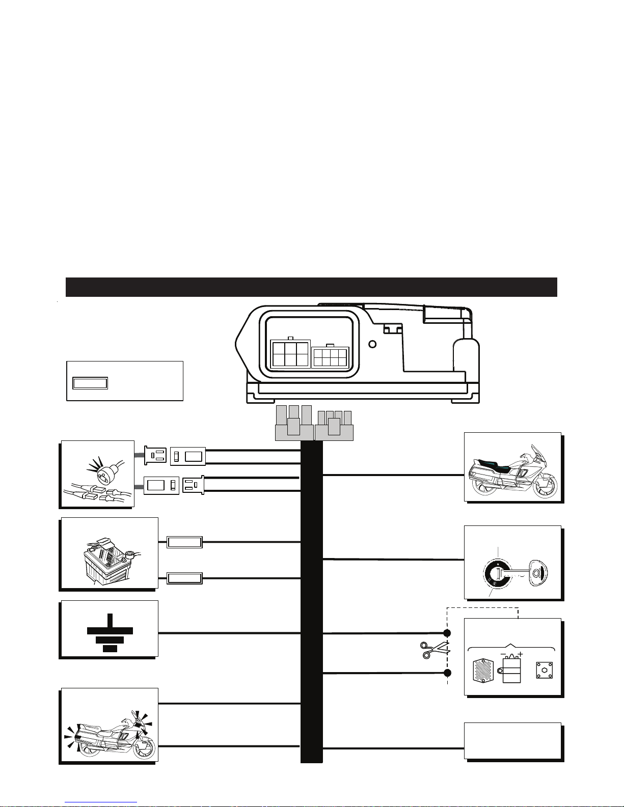
RED - Pos. 6B
GREEN - Pos. 7B
BROWN - Pos. 2A
ORANGE - Pos. 3A
ORANGE - Pos. 6A
PINK - Pos. 1B
POSITIVE OUTPUT
WHEN THE ALARM
IS ARMED
INDICATORS
YELLOW - Pos. 5B
+15/54 IGNITION
SWITCHED LIVE
SADDLE SWITCH
EARTH
+12V POSITIVE
3A
AMP
AMP
RED - Pos. 3B
BLACK - Pos. 2B
YELLOW - Pos. 4B
BROWN - Pos. 8B
GREY - Pos. 4A
WHITE - Pos. 5A
ENGINE
IMMOBILISATION
= FUSE TO BE
INSERTED
LEGEND:
COIL
ELECTRONIC
SWITCHI NG ON
FUEL
PUMP
A
8
1234
567
123
456
B
RECEPTACLE
RED/WHITE - Pos. 1A
15A
3.0 - CONNECTION DIAGRAM
- Connect the BROWN wire (power supply negative) to the negative terminal of the vehicle’s
battery - Connect the RED wire (12V positive power supply) to the positive terminal of the
vehicle’s battery using the 3A fuse.
- Connect the RED/WHITE wire (indicators 12V positive) to the positive terminal of the
vehicle’s battery using the 15A fuse.
- Connect the wire GREEN wire to the motor vehicle seat/bonnet/sidestand switch. 5 seconds
after the phase arming the alarm reads the switch position and it memorises it. A variation
of the condition memorised generates an alarm condition.
- The PINK wire is the positive output when the alarm is armed max current 80mA @ 25°C.
This output, if programmed, is active 5 seconds after the activation signals and it can be
used to command an additional module or a satellite.
- Connect the wires ORANGE wires to the motor vehicle indicators.
- Connect the YELLOW wire to an ignition switched live (+15/54) that remains live even
when the engine is being cranked.
- The WHITE AND GREY wires are used for the first engine immobilisation. Max current 7 A.
Page 5

4
4.0 - ALARM POSITIONING
5.0 - SET FUNCTIONS
The system is equipped with a “SET FUNCTIONS” which allows to program and customize
the alarm following to the user needs.
T o access to the SET FUNCTIONS:
1 - The alarm must be disarmed.
2 - Switch the motor vehicle ignition on, place the GT889 handsets contacts to the receptacle
and check that 5 quick beeps are emitted and the RED LED will switch on constant. The alarm
is in SET FUNCTIONS mode.
3 - After 5 seconds starting from the function No.1a sequence of LED beeps corresponding to
the function are emitted, the LED flashes can be GREEN or RED to indicate the function state.
The sequential cycle of the LED flashes (from the function No.1 to the No.8) is repeated twice
and after you come out from the SET FUNCTION.
4 - To select a function switch on-off the motor vehicle in correpondance of the relative signal,
the LED illuminatesof the colour which corresponds to the function state (test excluded).
5 - Within 10 seconds change the the function setting out by the OFF handset button. The
setting out change is confirmed by the change of the LED colour and by a beep. After 10
seconds, starting from the last function selected, the function sequence will start again.
The system is equipped with a “SENSOR” which allows to detect possible motor vehicle shocks/
movement. For an optimum operation pay attention to the fixing positions indicated below.
YES
YES
YES
YES
YES
HORIZONTAL PLANE
YES
YES
NO
HORIZONTAL PLANE
HORIZONTAL PLANE
NO
MAX 10°
YES
YES
WARNING:
- Before carrying out the definitive fixing it is suggested to place temporary the alarm
and check the correct operation of the shocks/movement sensor.
Page 6

5
T o come out from the SET FUNCTIONS:
Wait the end of the signal and place the GT889 handsets contacts to the receptacle (not
during the Function No. 3 - HANDSETS SELF-CODING). The exit is confirmed by the Led
switching off and by 5 beeps.
In the “FUNCTIONS TABLE” are mentioned the functions which can be selected.
SELF-CODING emergency procedure.
In case of GT889 handset-electronic key loss it is possible to enter the SET FUNCTIONS:
A - With the alarm disarmed disconnect the power supply and wait 1 minute.
B - Short-circuit the RECEPTACLE/LED with a metallic body the RECEPTACLE/LED
contacts.
C - Reconnect the power supply.
D - Turn the ignition key on-off 4 times (make a pause of 2 seconds at each state).
E - When the SET FUNCTIONS has been entered, this is confirmed by 5 BEEPS and by
the RED LED constant switching on.
F - Remove the short-circuit between the RECEPTACLE/LED contacts and proceed as
indicated in the self-coding procedure.
SET FUNCTIONS TABLE
FUNCTION STATE
No. DESCRIPTION
ENABLED DISABLED
1
SHOCKS/MOVEMENT SENSOR
SENSITIVITY ADJUSTMENT
GREEN
11
HIGH
RED
11
MEDIUM/HIGH
2
SHOCKS/MOVEMENT SENSOR
SENSITIVITY ADJUSTMENT
GREEN
22
MEDIUM/LOW
RED
22
LOW
3
REMOTE CONTROL HANDSETS
SELF-CODING
RED
33
NOT
AVAILABLE
4
RAPID TEST
RED
44
NOT
AVAILABLE
5
ACOUSTIC SIGNAL WHEN
ARMING/DISARMING
GREEN
55
RED
55
6
POSITIVE OUTPUT WHEN THE
ALARM IS ARMED
GREEN
66
RED
66
7
EMERGENCY INDICATORS
FLASH
GREEN
77
RED
77
8
AUTOMATIC ANTI-HIJACK
GREEN
88
RED
88
FUNCTION STATE
FUNCTION STATE
N1
N
N
2
N
N = N = Function No.
N = Led flashes No.
N = Beep No.
12
1
2
DEFINITE SETTING OUT
LEGEND:
- SHOCKS/MOVEMENT SENSOR SENSITIVITY ADJUSTMENT (Function No. 1 No. 2).
With this function it is possible to adjust the shocks/movement sensor sensitivity choosing
between 4 levels: high, medium/high, medium/low and low.
1 - Select the function and ENABLE/DISABLE pressing the “OFF” remote control handset
button.
Note: on the Led it is visualised only the active adjustment. For example if it is active the
High sensitivity the Led will emit 1 green flash during the function 1 and during the function
2 you will obtain 2 beeps without any Led signal.
Page 7

6
- RAPID TEST (Function No. 4).
With this function it is possible to check the correct system installation carrying out a test of
all the alarm lines.
SEA T/BONNET/SIDEST AND test switch: if the alarm line is triggered the system generates
5 beeps and 5 GREEN flashes of the LED on the receptacle.
SHOCKS/MOVEMENT SENSOR test: to test the position sensor it is necessary to wait 5
seconds from the function enabling before moving the motor vehicle. When the movement
is detected the system generates 2 beeps.
Ignition switched live test: if the alarm line is triggered the system generates 6 beeps and
6 flashes of the GREEN LED on the receptacle.
Wires cut test: removing the power supply to the alarm system a continuous s equence of
beeps will follow. To come ou from the function deactivate the system by the “OFF” button or
wait 30 seconds without triggering the alarm lines. In both ways you come out also from the
set functions.
- ACOUSTIC SIGNAL WHEN ARMING/DISARMING (Function No. 5).
It is possible to program the acoustic signal (beep) to indicate the alarm arming and the
disarming.
1 - Select the function and ENABLE/DISABLE pressing the “OFF” handset button.
- POSITIVE OUTPUT WHEN THE ALARM IS ARMED (Function No. 6).
This output, if enabled, is active 5 seconds after the arming, it can be used to command an
additional module or a satellite system.
1 - Select the function and ENABLE/DISABLE pressing the “OFF” handset button.
- INDICA
TORS EMERGENCY FLASH (Function No. 7).
This function allows to activate the four emergency flashes (hazard warning) pressing the
“OFF” remote control handset button with ignition key ON. The flash continues even removing
the vehicle ignition key. It is possible to activate and deactivate the system. To switch OFF
the four emergency flashes press the
“OFF” remote control handset button again with the
ignition key ON.
1 - Select the function and ENABLE/DISABLE pressing the “OFF” remote control handset
button.
-
AUT OMATIC ANTI-HIJACK (Function No. 8) (Available only with GT884N).
This function allows to block the motor vehicle in case the user is obliged to leav
e it with the
engine on ( theft attempt).
1 - Select the function and ENABLE/DISABLE pressing the “OFF” handset button.
- HANDSETS SELF-CODING (Function No.3).
With the function No. 3 it is possible to self-code new handsets to the control unit up to a
max. of 8.
1 - Select the function and press the “ON” button to be self-coded.
2 - The system confirm the correct handset self-coding by a flash of the GREEN LED and
by a beep.
WARNING:
- When you have entered the function the first handset which is self-coded deletes all
the other handsets memorised.
- If you want to add one or additional handsets you have to self-code all of them.
- If you try to self-code an handset already self-coded or the handsets maximum
number has been reached the system emits 3 anomaly beeps.
Page 8

7
6.0 - USER MANUAL
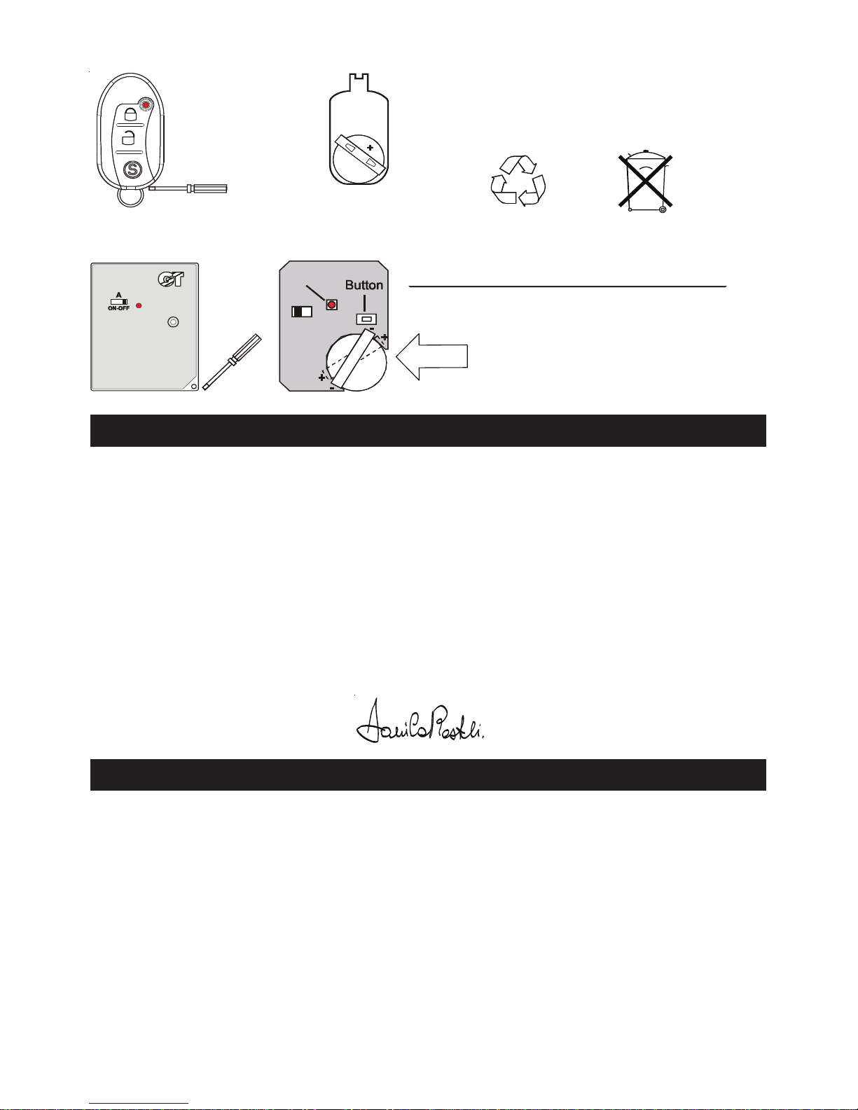
- HANDSET DESCRIPTION.
GT889: 3 buttons with electronic key incorporated.
GT884N: multifunction button (Optional).
It integrates a sensor which keeps the “LINK” transmission
active. If the sensor doesn’t detect vibrations for more than
2 minutes, it reduces the transmissions and so the battery
consumption. Note: avoid falls and shocks to not damage
the sensor.
-Button: to arm and disarm the alarm system.
- Switch: to activate/deactivate the automatic transmission.
- MANUAL ARMING/DISARMING.
ARMING: press the “ON” handset button, the arming is confirmed by an indicators flash, by a beep and
by the constant RED LED switching on for 30 seconds, after it start flashing.
DISARMING: press the “OFF” handset button, the disarming is confirmed by two indicators flashes, by
two beeps and by the LED switching off (the system emits 4 flashes and 4 beeps if during the
“surveillance” an alarm has been detected
and 5 additional beeps if an anomaly is present ).
- AUT OMATIC TRANSMISSION ENABLING/DISABLING (ONL Y WITH GT884N).
ENABLING: move the A switch to ON. To enable the “Link” function in the system carry out a manual
transmission (i.e. disarming).
To enable, activate the alarm system manually (i.e. arming).
DISABLING: move the A switch to OFF. To disable the “Link” function in the system carry out a
commutation with a remote control handset not in “Link” function.
- AUTOMATIC ARMING/DISARMING (ONL Y WITH GT884N).
ARMING: going away from the motor vehicle the system arms automatically. The arming is confirmed
by an indicators flash, by a Beep and by the RED LED constant switching on for 30 seconds, after that
it starts flashing.
Note: with the GT884 remote control handset (“Link”) it is not possible to arm the system manually, it is
possible only to disarm it.
DISARMING: when you come back to the motor vehicle, to disarm the system it is enough to have with
you the remote control handset in “AUTOMATIC TRANSMISSION-LINK” mode and turn the ignition key
on. The disarming is confirmed by two indicators flashes, by two beeps and by the LED switching off
(the system emits 4 flashes and 4 beeps if during the “surveillance” an alarm has been detected).
- SHOCKS/MOVEMENT SENSOR ISOLA TION (only with GT889).
In the first 5 seconds after the arming a press of the “ON” button deactivates the shocks/movement
sensor, the operation is confirmed by an indicators flash and by a Beep.
- P ANIC FUNCTION
- After 10 seconds from the arming press the “ON” button for one second, a sound alarm starts with
the contemporaneous indicators flash with a duration of 30 seconds.
- Press a second time on the “ON” button to stop it.
LED
BUTTON
GT884
(Opzional)
LED
SERVICES
BUTTON
ON
OFF
GT889
Page 9

8
- EMERGENCYDISARMING .
In case of emergency (i.e. handset low battery) it is possible to disarm the system placing on the
RECEPTACLE the electronic key integrated in the GT889 handset.
- IN CASE OF ALARM.
- Pressing the “OFF” handset button or approach with the handset in AUTOMATIC-TRANSMISSION-
LINK mode” to disarm the system.
Note: it is possible to stop the alarm without disarming the system pressing the ON GT889 handset
button.
- PRE-ALARM BY LINK.
If the system has been armed due to the “LINK” absence, the alarm causes are preceeded by a prealarm with BEEP and INDICATORS FLASH for 10 seconds.
- ANTI-HIJACK.
This function allows to block the motor vehicle in case the user is obliged to leave it with the engine on
( theft attempt).
A - AUTOMATIC ANTI-HIJACK.
The operation occurs only by the GT884N (optional) handset in “AUTOMA TIC TRANSMISSIONLINK” mode and with the Function No. 8 - AUTOMATIC ANTI-HIJACK enabled.
1 - With the ignition key on the LED illuminates constant RED to indicate that the anti-hijack procedure is
reserved. If the LINK signal is missing for more than 30 seconds the system enters the anti-hijack
phase.
2 -The LED illuminates constant GREEN.
3 - After 15 seconds the indicators start flashing.
4 - After other 15 seconds the system emits an alarm cycle with a duration of 30 seconds. If the ignition
key condition continues another alarm cycle is generated.
5 - When the ignition key is switched off, the engine immobilisation is activated and it will block the
starting. To the following vehicle ignition attempts an alarm cycle will be generated.
6 - To come out from the anti-hijack phase, in any phase, it is necessary to have the same handset in
AUTOMATIC-LINK TRANSMISSION which has activated the function and to get closer to the motor
vehicle.The confirmation is given by two flashes of the indicators, by two beeps and by the LED
switching off.
B - MANUAL ANTI-HIJACK.
The operation occurs only by the GT889 handset enabled for ANTI-HIJACK.
1 - With the ignition key on press the GT889 “SERVICE” handset button.
2 -An indicators flash and the GREEN LED switching on confirm that the ANTI-HIJACK function has
been activated.
3 - After 15 seconds the indicators start flashing.
4 - After other 15 seconds the system emits an alarm cycle with a duration of 30 seconds. If the ignition
remains on another alarm cycle is generated.
5 - When the ignition key is off the engine immobilisation is activated and it stops the vehicle starting. An
alarm cycle will be generated by attempting to start the vehicle.
6 - To come out from the anti-hijack state, from any phase, it is necessary to have the same GT889
remote control handset which has activated the function and press the “SERVICE” handset button. The
operation will be confirmed by two indicators flashes, two siren Beeps and by the LED switching off.
ENABLE/DISABLE THE ANTI-HIJACK FUNCTION:
1 - Open the GT889 remote control handset, remove the battery and wait the led signalling.
2 - Press the "OFF" button and close the remote control handset.
3 - Keeping the "OFF" button depressed insert the battery in the remote control handset and wait the
led signalling.
4 - If the led remains illuminated constant the function is ENABLED, if the led flashes the function is
DISABLED.
Page 10

9
5 - Release the "OFF" button and close the remote control handset.
6 - To change the function state repeat the procedure from the point 1 (at each repetition of the
procedure the function changes state).
- PROTECTIONS.
When the system is armed the status check LED switches constant on, after 30 seconds the LED
flashes. The ignition key , seat/bonnet/sidestand and wires cut protections are active 5 seconds
after the arming, while the shocks/movement sensor is active when the status check LED
flashes.
- SLEEP MODE (POWER SA VE).
To protect the motor vehicle battery the system operates a constant monitoring of the power supply
voltage and/or reduction of the available functions in the time.
MOTOR VEHICLE BATTERY MONITORING: when the system is disarmed, if the battery reaches the
threshold of 8V the alarm places in “SLEEP MODE” .
SLEEP MODE WHEN THE ALARM IS DISARMED: when the alarm is disarmed, after 10 days the system
places automatically in “SLEEP MODE”. To reactivate the alarm switch the ignition key on.
SLEEP MODE WHEN THE ALARM IS ARMED: after 5 days the system doesn’t accept the handset
command anymore, but all the protections remain active. The normal operation is restored in case of
alarm. In this condition the first cycle is preceeded by a pre-alarm signal (beeps) of 10 seconds.
During the pre-alarm it is possible to disarm the system.
- INDICA TORS EMERGENCY FLASH (only with GT889).
- To activate the indicators flash turn the motor vehicle ignition key on and press the “OFF” handset
button. Note 1: the flash continues even removing the key. Note 2: during the indicators flash is
however possible to arm/disarm the system.
- To stop the indicators flash turn the motor vehicle ignition key on and press the “OFF” handset button.
- SERVICE MODE.
For the motor vehicle servicing, i.e. in winter, it is possible to place the alarm in SERVICE MODE.
1 - Turn the ignition key on and press the “ON” handset button. The system confirms the operation with
3 flashes of the RED LED.
2 - Turn the ignition key off and after 120 seconds the system places in POWER SAVE with a current
consumption of very few microampere.
3 - To come out from the SERVICE MODE switch the ignition key on and arm the alarm with the handset
during the 120 seconds.
- BACKUP BA TTERY RECHARGE.
The device is equipped with internal battery to manage possible alarms due to tamperings on the
electrical system when the thesystem is armed. The battery recharge occurs only with the motor
vehicle ignition switched on. To recharge completely the battery 24 hours are needed.
- ALARMS CHECK CONTROL AND ANOMALIES.
If during the surveillance state an alarm has been detected (4 indicators flashes and 4 beeps to the
disarming) or there is anomaly it is possible to check the cause.
When the alarm is disarmed switch the ignition key on and check the LED flash as indicated in the
ALA RMS SIGNAL TABLE and ANOMALIES SIGNALS TABLE.
- Motor vehicle low battery indication: when disarming with the handset if the motor vehicle
battery is at 11,6V the system doesn’t activate the indicators and after the normal acoustic signalling
emits 5 anomaly beeps and when it is triggering it doesn’t activate the indicators.
Page 11

10
- The signals sequence of occurred alarms and anomalies detected is repeated at each
motor vehicle switching on. .
- The alarm system memory is deleted to the following alarm system arming.
- When the anomaly is solved, the memory is automatically deleted.
WARNING:
7.0 - MAINTENANCE AND WARNINGS
MOTOR VEHICLE W ASHING .
It is necessary to pay particular attention to any source of water spray. It is advisable, during this
operation to protect it with a covering (i.e. cellophane).
- FUNCTIONS CHECK.
To have an always efficient system it is advisable to carry a periodic check of all the functions.
- HANDSET .
Do not expose the handset to excessive heat sources, water and
shocks. For the battery replacement refer the picture below.
The battery selling off has to always occur in appropriate way and
it has to be in compliance with the local rules in force.
- PRACTICAL ADVICES.
The GT884 remote control handset operates through radio waves.
Avoid to place it in zones which could compromise the operation (hip
pockets, bags, etc.). Do not put together the remote control handset
with the automatic transmission enabled to the bunch of keys.
ALARMS SIGNALS TABLES
Status check LED
flashes number
Input which has
generated the alarm
RED
PAUSE
2
SHOCKS/MOVEMENT
SENSOR
RED
PAUSE
5
SEAT or BONNET or
SIDESTAND
RED
PAUSE
6
MOTORCYCLE
INSTRUMENT PANEL
RED
PAUSE
7
WIRES CUT
ANOMALIES SIGNALS TABLE
Status check LED
flashes number
Cause which has
generated the anomaly
RED/GREEN
HANDSETS
BATTERY
SYSTEM STATE TABLE
LED Colour State
RED
Constant on
SYSTEM IN PHASE OF ARMING
ROSSO
Slow flash
ARMED SYSTEM
COLOUR
COLOUR
COLOUR
N
N = Flashes No.
COLOUR = Flash colour
FLASHING LED
LED CONSTANT ON
LEGEND:
Flashes without pause
RED/GREEN
NO
Page 12
11
- HOW TO REPLACE THE HANDSETS BA TTERY . \
8.0 - COMPLIANCE DECLARATION
Getronic S.r.l. Via Calcinate, 12 Gavirate, Italy hereby declares that GT970 is in compliance
with the following European Directive:
R97
All Getronic products are compatible with the vehicle’s original electronic systems.
The GT889/884 remote control handsets are in compliance with the following European
Directives as issued by the European Community:
EMCC DR. RASEC “Notified Body 0678”
R&TTE 1999/5/CE (including the directives: EN 300 220 - EN 60950)
Chairman of the board
Danilo Restelli
- Power supply: 9-16V.
- Working temperature: -40° / +85°.
- Max apllicable voltage: 36V/1minute
- Current draw - disarmed system: <800μA.
- Current draw - armed system: <1.5mA.
- Current in “SLEEP MODE”: <20μA.
- Max current for engineS immobilisations 7A.
- Max current Blinker outputs: 5A.
- Max current Led output: 25mA.
- Max current positive output: 80mA.
- Serial Output/Input monowire: 4800 Kb.
- Self-power supply: Battery 7,2V Ni-Mh - 120mA
- Alarm and Panic time: 30 seconds
9.0 - TECHNICAL DATA
WARNING!
- The battery negative terminal has to be
pointed upwards (with components) and the
positive downwards (handset bottom).
Li Li
Replace with a Lithium battery
Mod. CR2032 (3V) for GT889
Mod. CR2450 (3V) for
Take out and insert the battery
from this circuit side.
GT884
-
With care lever the front case for th
e
printed circuit
WARNING:
the batteries selling off has to always
occur in appropriate way and it has to be in
compliance with the local rules in force.
LED
Page 13
12
CUT AND KEEPCUT AND KEEP
InstManGT970-UKRev07.p65
This Certificate should be kept in a safe place and produced for verification should technical
assistance be required. Inability to produce this Certificate may affect your warranty rights.
Warranty period bengins from date of purchase and is valid for 24 months.
Should technical assistance be required during the warranty period, you should take your
vehicle and this Certificate to either the original installer or the nearest GT Auto Alarm
Service Centre for inspection. Should any part of the security system be found to be
defective, and providing all component parts of the system are of GT Auto Alarm manufacture,
the defective part will be replaced or repaired free of charge. Warranty replacement/repair
does not include the following items:
1) damage caused in transit/carriage; 2)damage caused by incorrect or poor installation;
problems which may be caused by anomalies in the vehicle’s electrical system or
originating from the environment in which the system is operated. 3) damage caused by
carelessness, negligence, misuse or repair by unauthorised personnel.
Units returned to our organisation under the terms of the warranty will be replaced or
repaired within a reasonable time period according to our Company requirements.
Any repair/refurbishment received within the warranty period does not extend or renew the
warranty itself.
Nobody is authorized to modify or replace anything in verbal or written format which alters
the conditions of this warranty.
The manufacturer reserves the right to modify or improve the specification.
The alarm only defdeters burglary attempts. Our company cannot accept liability for any
consequential damage or loss to persons or property as a result of purchase of a GT Auto
Alarm system.
Any correspondence for litigation purposes shall be received at our headquarters in
Gavirate (Varese) - Italy.
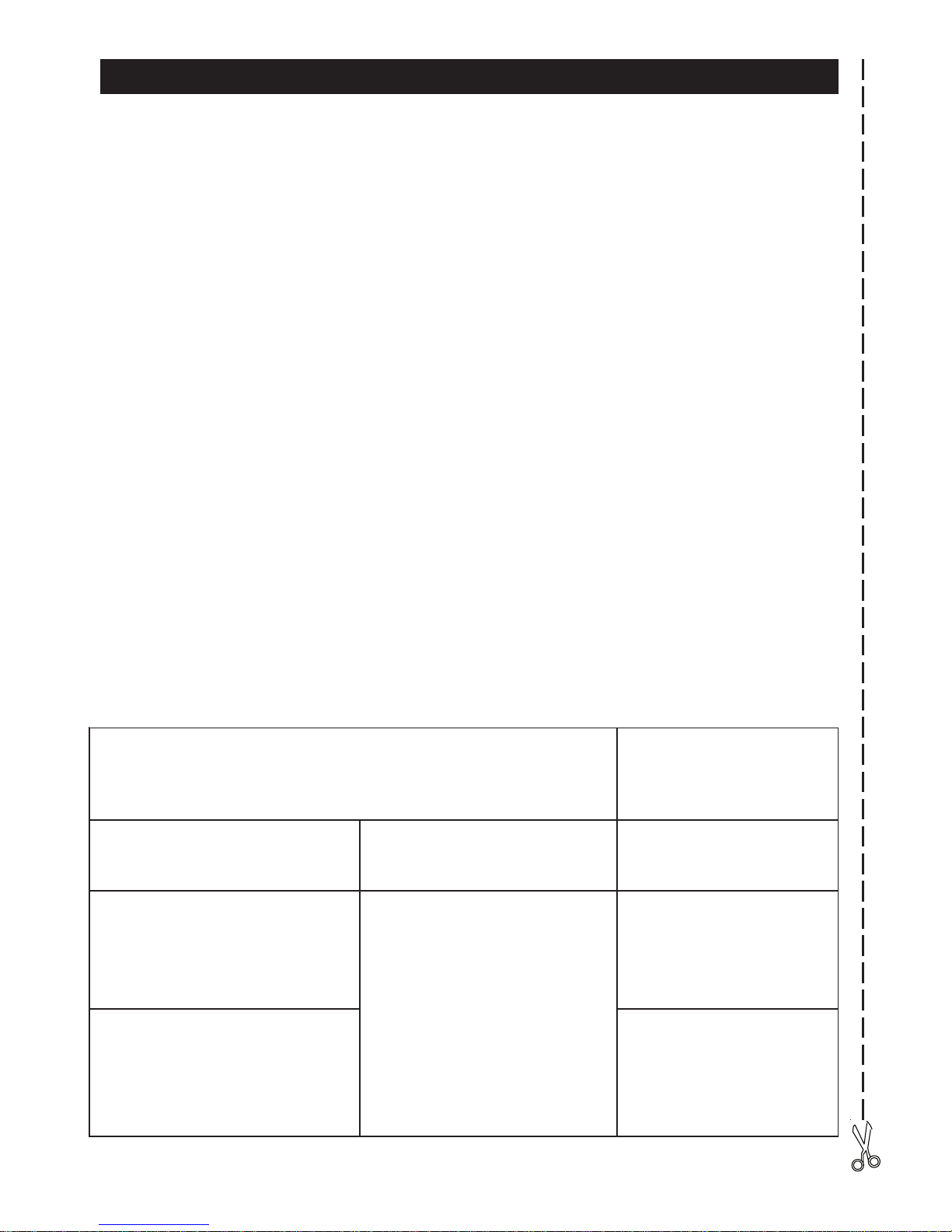
10.0 - W ARRANTY CONDITIONS
etacifitreCnoitallatsnI
tuodeirracneebsahnoitallatsnimetsysmralaehttahtyfitreceW
dednahneebsahatadlacinhcetehttahtdnagnittifesehtgniwollof
.revo
nopuocytnarraW
ledommralA
:LEDOMMRALA:ETADNOITALLATSNI:SEIROSSECCADELLATSNI
DELLATSNIELBISSOP
:SEIROSSECCA
RELLATSNIDNAPMATS
:ERUTANGIS
:ETADNOITALLATSNI
:LEDOMELCIHEVROTOMDNAEKAM RELLATSNIDNAPMATS
ERUTANGIS
Page 14

По вопросам продаж и поддержки обращайтесь:
Архангельск (8182)63-90-72
Астана +7(7172)727-132
Белгород (4722)40-23-64
Брянск (4832)59-03-52
Владивосток (423)249-28-31
Волгоград (844)278-03-48
Вологда (8172)26-41-59
Воронеж (473)204-51-73
Екатеринбург (343)384-55-89
Иваново (4932)77-34-06
Ижевск (3412)26-03-58
Казань (843)206-01-48
Калининград (4012)72-03-81
Калуга (4842)92-23-67
Кемерово (3842)65-04-62
Киров (8332)68-02-04
Краснодар (861)203-40-90
Красноярск (391)204-63-61
Курск (4712)77-13-04
Липецк (4742)52-20-81
Магнитогорск (3519)55-03-13
Москва (495)268-04-70
Мурманск (8152)59-64-93
Набережные Челны (8552)20-53-41
Нижний Новгород (831)429-08-12
Новокузнецк (3843)20-46-81
Новосибирск (383)227-86-73
Орел (4862)44-53-42
Оренбург (3532)37-68-04
Пенза (8412)22-31-16
Пермь (342)205-81-47
Ростов-на-Дону (863)308-18-15
Рязань (4912)46-61-64
Самара (846)206-03-16
Санкт-Петербург (812)309-46-40
Саратов (845)249-38-78
Смоленск (4812)29-41-54
Сочи (862)225-72-31
Ставрополь (8652)20-65-13
Тверь (4822)63-31-35
Томск (3822)98-41-53
Тула (4872)74-02-29
Тюмень (3452)66-21-18
Ульяновск (8422)24-23-59
Уфа (347)229-48-12
Челябинск (351)202-03-61
Череповец (8202)49-02-64
Ярославль (4852)69-52-93
сайт: www.jablotron.nt-rt.ru || эл. почта: jnb@nt-rt.ru
 Loading...