

Page 1
GSM pager CA-1202 „Athos“ 4/4 MHF52706
11 Internet remote access
The web site www.GSMLink.cz enables GSM pager remote control (to
users) and setting (to installers). The following features are enabled:
To get internet access to an installed and powered GSM pager you will
first be asked to register your GSM pager on the first page. You will find a
unique registration code for your GSM pager on the warranty card.
11.1 Reset GSM
If you need to disconnect and then reconnect the GSM module to the GSM
network, then use the command “MASTER RESET GSM”.
This does not affect any settings and is typically used for GPRS activation or
charging up credit. This command always requires the Master code.
12 Central monitoring station communication
The GSM pager allows central monitoring via GPRS data protocol. The
central monitoring station (CMS) gets arming, disarming and alarm
information. It also regularly checks the communication link to the car after it is
armed. So if anyone tries to tamper with GSM pager communications, it will
indicate an alarm at the CMS.
13 Additional features
13.1 Car battery low voltage reporting
The GSM pager checks the voltage of the car battery. If the voltage is too
low (10V) it will notify users via an SMS message. This avoids complete
discharging of the car battery if you forget to turn off your lights etc.
13.2 Back-up battery
The GSM pager can be backed up by a BB-01 battery. Thus, the GSM
pager can keep sending information. Back up time is provided for several
hours. The manufacturer recommends regular BB-01 checking once a year.
The battery should be replaced every two years. Low voltage of the back up
battery (below 4V) is reported to the user via SMS (change the battery in this
case).
13.3 Car location
If your GSM provider offers a location service, you have to activate the
LOCATOR command after installation by the following SMS sequence:
MASTER LOCATOR xx…x
where: MASTER is the installers code
xx...x is the provider’s sequence to obtain the position
of the GSM pager SIM card (check with your
GSM provider for details)
After this sequence has been sent successfully once, the GSM pager
memorizes the parameters and from this moment on you can obtain the
location of the car by just sending the instruction LOCATOR.
Note: GSM location service may not be available in some countries.
13.4 Pre-paid SIM card balance
It is recommended not to use prepaid cards in the GSM pager. If you
have no other choice than prepaid cards, you can enable the CREDIT
instruction by following sequence:
MASTER CREDIT uuu..u xx yyy zz
where: uuu…u is the provider’s code to obtain the balance
xx is the time period (in days) for regular checking
yyy is the threshold level below which the balance is
reported to the user (TEL1)
zz is the position of the first digit of the balance in the reply
SMS from the provider
• After this sequence has been sent once, the GSM pager will check
the balance automatically every xx days and if the balance is lower
than yyy the user will be notified (TEL1)
• If the CREDIT instruction is enabled in the above way, the user can
also obtain the current balance by the instruction CREDIT
• To disable the automatic balance checking set the time period “xx”
to 00.
13.5 Roaming
If you travel abroad and your SIM card supports roaming, the GSM pager
will work there too.
13.6 Siren activation
If you are searching for a stolen car, you can operate the siren
remotely by the following SMS instructions:
MASTER SIREN turns the siren on for 10 minutes
MASTER SIREN ON siren on permanently
MASTER SIREN OFF siren off
To avoid misuse of this option, only an installer can switch the siren on.
13.7 LED indicator signals
LED state Meaning
OFF Disarmed
permanently ON connecting to a GSM network or a phone call
Regular slow flashing Armed
Regular fast flashing Alarm memory
Interrupted light Car was stopped (immobilization)
Flashing after ignition off GSM network is not available
Flashes after ignition on Number of enrolled remote controls
14 Specification
Power supply 12V DC (8-16V)
Stand-by consumption max. 10 mA
Max. consumption (during GSM communication) 1 A
GSM band 900 / 1800 MHz dual band system, power class 4
Transmitted power 2 W /GSM900, 1 W /GSM1800
VF frequency 433,92MHz
Working temperature -20°C to +70°C
Output SIR +12V, max. load 1,3A
Immobilization 8A permanently, 12A for 30 seconds
Central locking outputs max. 200mA, to GND
pulses 0,3s, 4s or 60s (optional)
Complies with ECE Rugulation No. 97.00, 10
Can be operated according to ERC/DEC98(20,21)
Health and safety ČSN EN 60950
EMC ČSN ETSI EN 301489-1, ČSN ETS 300683
radio interferences ČSN ETSI EN 301419-1, EN 301511, ČSN ETSI EN 300220
Hereby, Jablotron Ltd., declares that this CA-1202 is in compliance with the
essential requirements and other relevant provisions of Directive 1989/336/EC
and 1999/5/EC.
Original of the conformity assessment can be found at the web page
www.jablotron.com, section Technical support
Note: Although this product does not contain any harmful materials we
suggest you to return the product to the dealer or directly to the producer
after usage.
GSM pager CA-1202 „Athos“ 1/4 MHF52706
CA-1202 “Athos” installation manual
MODE 3 – GSM pager for cars with an installed car alarm
Main features for this mode:
• Sending of alarm SMS messages to up to 4 phones.
• Dialing and acoustic alarm warning to up to 4 phones.
• Location tracking of the car (using the triangulation feature of the
GSM provider)
• Central monitoring of the car when armed (fully supervised GPRS
protocol)
• Remote immobilization of the car via SMS instructions.
• Remote control of the alarm system and the central locking via SMS
instructions.
• Optional – Hands-free calling (receiving of any incoming call and
dialing up to four pre-programmed phone numbers)
• Remote internet alarm access (user and installer levels) via
www.GSMLink.cz
1 Before installation
The CA-1202 should only be installed by a professional installer. The
manufacturer assumes no liability for damages caused by incorrect
installation or use of this product.
The Athos GSM pager is suitable for cars with 12 V and negative
grounding. The main unit is designed for installation in the passenger
cabin.
Disconnect the car battery before starting installation; study the car
owner manual first. Avoid drilling into the metal parts of the car body.
Note: Use only proper crimping tools and parts to make connections. Cut
all unused wires and insulate them properly.
The thin wire which leads directly out of the central unit is the remote
control and wireless detector antenna. The location of this wire affects the
communication range. Place the antenna on a suitable plastic surface so
that the other wires do not screen it.
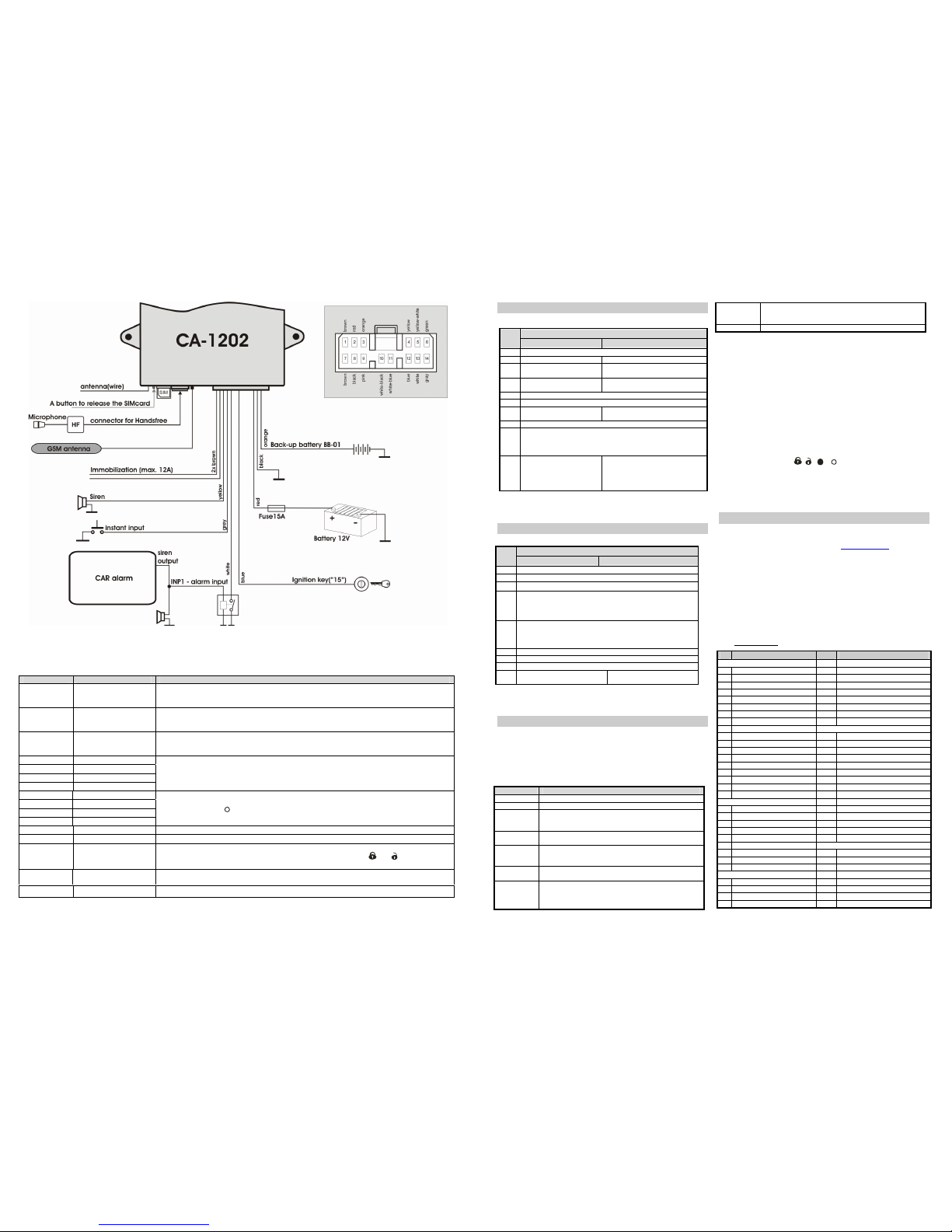
2 Wiring
• YELLOW – siren output (+12V / max. 1,3A).
• Gray – instant activation input reacts to connection or disconnection
from the ground (automatically recognizes logic).
• WHITE – INP1 input - reacts to connection or disconnection from the
ground (automatically recognizes logic). Reaction delay is 3 seconds
• BLUE –- ignition key input (+12V). Be sure, that there is +12V while the
key is on and while starting.
• GREEN – LED indicator – install it in a visible spot on the dashboard.
Connect the other end of this lead to the GND.
• BLACK – GND – connect to the original grounding in the car.
• RED – power supply +12V - connect directly to the battery. Check that
the installation is properly finished and that the GSM antenna is
connected before powering up!!
• ORANGE – back-up battery – connect a BB-01 optional battery
(Jablotron) i f desired. If the BB-01 is not connected, then ground the wire.
• 2x BROWN – immobilization circuit (8A permanently, max. 12A /
3minutes).
• Pink – not used
3 SIM card insertion
1. Make sure, that the PIN password on the SIM is disabled. You can
do this using a mobile phone (e.g. for NOKIA: MENU, SETTINGS,
SECURITY SETTINGS, PIN CODE REQUEST, OFF). If your SIM card
does not allow switching the PIN off, change the PIN to 0000.
2. Activate the SIM card if necessary (see provider’s instructions),
ensure that it works (by a mobile phone) and record its phone number.
3. Using a thin pointed tool, press the colored button to release the SIM
cardholder. Insert the SIM card into the holder with the gold contacts
facing up and then reinsert the holder.
4 GSM antenna installation
DO NOT switch the power on before the GSM antenna is connected.
The provided antenna is adhesive and should be attached to the car window.
The antenna should not be obstructed by any metal parts. It is recommend to
install the antenna in a place where it is not easily visible (a tinted part of the
window, behind the mirror etc.). If the car has an original GSM antenna
installed, it can be used (if the connector is different, use an appropriate
adapter).
5 Initial powering-up of the GSM pager
Make sure, that the GSM antenna is connected, the SIM card inserted
and the wire harness installed properly. Then connect the power (car
battery). The LED indicator will turn on and the siren will make a short
chirp. Wait until the LED turns off (up to 1 minute).
If the LED starts to flash, no GSM network was found. In such a case
turn the power off, remove the SIM card and try to use it in a mobile
phone (at the place where the GSM antenna is). Check also if the PIN
protection is OFF (or set to 0000). If the SIM card logs into a network
successfully, reinsert it in to the pager and repeat powering-up.
After the GSM pager is powered up, you have to:
a) Select Mode 3 by the command RESET EN 3
b) Enroll remote controls (if used)
c) Set the programmable features (phone numbers, DIP, SET,
etc.).
These can be done by:
• SMS instructio ns – see table 6.1. For example sending an SMS:
MASTER RESET EN 1 to the GSM pager will select Mode 1.
• Internet page : www.GSMlink.cz
is the most convenient way. To
register there you need to know the registration code (printed on
the warranty card) and the master code (factory default is
MASTER).
• SIM Card phone directory editing (see table 6.1 for list of features
which can be programmed this way). After the initial powering-up a
list of parameters is created in the SIM card phone directory. If you
then insert the SIM card in to a mobile phone, you can set
particular features (by entering numbers into the created list). The
entry for Mode setting is not automatically created, but it is possible
to make a new entry with the name: RESET EN and the number: 1.
Data entered this way are read by the GSM pager after the SIM
card is reinserted. For security reasons it is erased after reading.
6 Enrollment of remote controls
Up to 4 RC-4x remote controllers and can be enrolled to the GSM pager
(after Mode 3 is selected by the RESET EN 3 instruction).
Remote control enrollment:
1. Switch the ignition on
2. Send the SMS instruction: MASTER LEARN RC
• If the siren is connected to the GSM pager it will chirp 3x and the
LED will start flashing.
3. Press and hold buttons
and together for 3 sec on the remote
control.
• A siren chirp confirms the enrollment.
• By enrolling the first remote control all other remote controls
previously enrolled will be erased (all the remote controls you
want to use must be enrolled during the same enrollment
session).
4. Exit enrollment by turning the ignition off.
Page 2
GSM pager CA-1202 „Athos“ 2/4 MHF52706
Figure 1: installation of the GSM pager in Mode 3
6.1 Programming seque nces
Enter the prescribed spaces in SMS texts as shown in the table below. MASTER is a factory default master code, which should be changed to your own
password. All SMS texts are case insensitive.
* See part 5 for details.
SIM entry* Text of SMS instruction Description
RESET EN 3 MASTER RESET EN 3 Mode setting. Factory default is 0 – no function (immobilization relay copies ignition). Note: By
performing the RESET EN x instruction, all settings, remote controllers and enrolled wireless detectors
will be erased! RESET is indicated by four siren chirps.
Not possible MASTER UC uuuu
User Code setting – the code (password) allows you to operate the alarm remotely via SMS from
unauthorized phones. uuuu is a new user code, up to 8 characters (A –Z & 0 – 9). Factory default
user code is USER
Not possible MASTER MC xxxx Master Code setting, xxxx is a new master code, up to 8 characters (A –Z & 0 – 9).
The code allows you to change settings of the GSM pager. Factory default master code is MASTER
TEL1 xx...x MASTER TEL1 xx...x
TEL2 xx...x MASTER TEL2 xx...x
TEL3 xx...x MASTER TEL3 xx...x
TEL4 xx...x MASTER TEL4 xx...x
Setting of phone numbers to report alarms (these phones will also be authorized to control the
GSM pager via SMS without a user password)
E.g.: MASTER TEL2 +420602123456 will enter the phone number into the TEL2 memory
MASTER TEL3 0 will erase the TEL3 memory.
DIAL1 xx...x MASTER DIAL1 xx...x
DIAL2 xx...x MASTER DIAL2 xx...x
DIALA xx...x MASTER DIALA xx...x
DIALB xx...x MASTER DIALB xx...x
Setting of phone numbers to dial using Hands free.
E.g.: MASTER DIAL2 +420602123456 will enter the number into the DIAL2 memory (which is dialed
after you press button
on the remote control)
MASTER DIAL2 0 will erase the memory DIAL2.
DIP abcdefghij MASTER DIP abcdefghij DIP parameter entry – see part 7
SET abcdefghi MASTER SET abcdefghi SET parameter entr y – see part 8
Not possible MASTER LEARN RC Remote Control enrollment - up to 4 controllers can be enrolled, turn the ignition key on before
sending the instruction. To enroll a remote control press and hold buttons
and together for 3
seconds. After you enroll all remote controls, turn the ignition key off.
Not possible MASTER TXT 01,text Editing of SMS texts (reports and instructions), see part 10
TELU xx...x MASTER TELU xx...x Sustain call setting (for pre-paid cards) 1 x a month the xx..x number is called, call duration 10 s.
GSM pager CA-1202 „Athos“ 3/4 MHF52706
7 DIP parameters
By SMS: MASTER DIP ABCDEFGHIJ you can change 10 features:
Description
DIP
0 1
A no function in Mode 3 (set to 0)
B Silent alarm
Audible alarm (30 sec.)
C
SMS alarm report only
SMS alarm report + siren sound
phone call
D SMS remote control not
confirmed by SMS reply
SMS remote control instructions
confirmed by SMS reply
E no function in Mode 3 (set to 0)
F no function in Mode 3 (set to 0)
G
User can not change SMS
texts
User can change SMS texts by TXT
sequence
H no function in Mode 3 (set to 0)
I
0 = Immobilization by arming and by SMS instruction
1 = Immobilization by arming and automatically 5 minutes after ignition is
turned off and also by SMS instruction
2 = Immobilization only by SMS instruction
J
Self-location disabled
The car´s location will be sent by
SMS to numbers TEL1 to TEL4 if
there is an alarm or if the car stops
after the immobilization SMS
instruction (See 13.6.)
Factory default setting is DIP 1111000000 (bold letters in the text). If you
want to change only particular parameters, enter x for the others (i.e.
MASTER DIP x0xxxxxxxx).
8 SET parameters
By SMS: MASTER SET ABCDEFGHI you can change 9 features:
Description
SET
0 1
A no function in Mode 3 (set to 0)
B no function in Mode 3 (set to 0)
C no function in Mode 3 (set to 0)
D
Instant activation input logic:
0 = automatic
1 = activated by falling edge (grounding)
2 = activated by rising edge (disconnecting from GND)
E INP1 logic:
0 = automatic
1 = activated by falling edge (grounding)
2 = activated by rising edge (disconnecting from GND)
F no function in Mode 3 (set to 0)
G no function in Mode 3 (set to 0)
H no function in Mode 3 (set to 0)
I
Do not switch off the GSM
module
Switch off the GSM module
after 30 minutes of idle
Factory default setting SET 100000010 (bold letters in the text).
If you want to change only particular parameters, enter x for the others
(i.e. MASTER SET xxx0xxxxx).
9 User instructions
9.1 Remote control by SMS instructions
SMS instructions sent from an authorized phone (TEL1 to TEL4) can operate
the GSM pager remotely. Factory default instruction texts are shown in the
following table. The instruction texts can be changed by SMS text editing,
see part 10.
If an SMS is sent from an unauthorized phone (other than TEL1 to TEL4), a
valid user code must be entered before the instruction (e.g. USER IMO).
SMS text Description
IMO
STOP (immobilize) the car (after turning the ignition key off)
UNIMO
Unblock (mobilize) the car
STATUS
The GSM pager will reply with status information, e.g. “car
reports: Time: 27.01.04 13:04, Status: Armed, Unblocked,
Ignition off“.
HELP
The GSM pager will reply with a brief list of SMS
instructions.
UC uuuu To change the user code. uuuu is the new user code, up to
8 characters (A –Z & 0 – 9). Factory default user code is
USER
CREDIT
To obtain the balance of a prepaid SIM card if used. See
13.5 for details
HF abcdef
Hands-free set adjustment:
a – enable calls (0= disabled, 1=enabled)
b – auto answer incoming calls (0= disabled, 1=enabled)
c – microphone sensitivity 0 to 9, (5)
d – speaker volume 0 to 9, (5)
e - ringing tone volume 0=mute to 9=max., (5)
f – ringing sound 0 to 9, (5)
LOCATOR
To obtain the car location from the GSM provider. See 13.4
• The parameters in bold are factory defaults.
• The instruction must contain spaces as shown in the table
• Only basic ASCII can be used in the SMS instruction texts
• If the SMS text contains the % sign, then the following text will be ignored.
9.2 Phone calls by an installed hands free set
If the optional HF-03 hands free set is installed, it is possible to receive
and make phone calls via the GSM pager. When the ignition key is on,
the remote control (RC-4x) allows you to operate the hands free set.
Incoming calls – to answer them, press any button on the RC-4x remote
control. By pressing any button again, the call will be terminated.
When armed, all incoming calls are automatically rejected. If the car is
blocked (by IMO instruction) all calls are automatically answered (it is possible
to listen and to speak to the car remotely). Automatic call answering while you
are driving can also be enabled by the HF instruction (see 9.1).
To make a call – you can call up to 4 preprogrammed numbers while you are
driving. By pressing button
, , or on the remote control you will dial
the corresponding number (pre-programmed by DIALA to DIAL2, see 6.1)
9.3 Alarm
When an alarm is triggered, the siren will sound for 30 sec., warning SMS
messages will be sent to all phones (TEL1 to TEL4) and these phones will
also be called with the siren sound.
10 SMS text editing
The SMS texts (alarm information and instructions) are factory
preprogrammed. However, it is possible to change these texts by a
mobile phone or via internet access using www.GSMlink.cz
To change a text by mobile phone, send the SMS:
MASTER TXT zz,text,zz,text,…
where: zz is the text index (see the following table)
text is your new text – up to 30 characters, full stop (dot) or
comma cannot be used in the text, spaces are allowed
Example: MASTER TXT 01,LOCK PLEASE
By changing text numbers 01 to 16, you will modify the control SMS
instructions. This allows you to customize the remote control of the car.
You can also make your own password part of the instruction to increase
the security of the mobile phone remote access.
10.1 SMS text table
zz Factory default text zz Factory default text
SMS commands:
34 W ireless detector
01 AM 35 Current detector
02 DM 36 Telephone 1
03 IMO 37 Telephone 2
04 UNIMO 38 Telephone 3
05 STATUS 39 Telephone 4
06 HELP 40 Telephone - UC
07 CREDIT 41 Telephone - MC
08 DIAL 42 Remote controller
09 HF
Status information:
10 LOCATOR 50 Car alarm reports:
11 MC 51 Status:
12 UC 52 Armed
13 DIP 53 Disarmed
14 TEL 54 Ignition key ON
15 LEARN RC 55 Ignition key OFF
16 LEARN JA 56 Engine is blocked
17 SIREN 57 Engine is unblocked
18 SET 58 No alarm
Events:
59 Alarm timeout
20 Alarm 60 Low accumulator voltage
21 Alarm canceled by a user 61 Power failure
22 Fire alarm 62 Power recovery
23 Tamper alarm 63 Time:
24 Disarming 64 Low battery voltage
25 Arming
Confirmation SMS:
26 Low battery voltage 70 Command accepted
27 Engine is blocked 71 Command syntax error
28 Engine is unblocked 72 New MC code:
Source:
73 New UC code:
30 Ignition key 74 Reset
31 Door contact 75 Registered phone number:
32 INP1 activation 76 Credit:
33 INP2 activation 77 LEARN mode, enrolled
The gray texts are not available in mode 3.
 Loading...