

Page 1
The AC-82 wireless relay output module MJT51202
1
The AC-82 wireless relay output module
The AC-82 is a component of Jablotron’s Oasis JA-80 system. It is
mains-powered (230V AC) and it provides 2 relays which can be
controlled by radio signals and offers the following:
• Remotely controllable relay outputs which follow JA-80 control
panel programmable PG outputs
• Remote control of appliances using RC-8x controllers
• Relay output of JA-8x wireless detectors
• Relay output of TP-8x wireless thermostats
1
2
3
4
R
A
D
I
O
max F 5 A / 250V
buttons
LEDs
fuse
max 5 A
X
Y
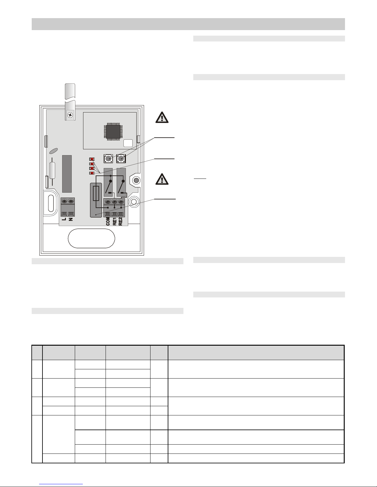
Installation
Installation of this module shall only be undertaken by technicians holding a
certificate issued by an authorized distributor.
.
Warning: this device is galvanically connected to the mains.
Open the module’s cover (1 screw) and take out the circuit board (2
tabs). Install the back part of the housing to the desired place, re-install
the circuit board, connect the wires and enroll the desired wireless
devices.
Terminals
L,N Power: 230V AC/50Hz
COM Common terminal for the output contacts X and Y (fused by a 5
Amp fuse)
RE1 Normally open relay X contact
RE2 Normally open relay Y contact
The enrollment of transmitters
The X and Y relays are totally independent. Jablotron Oasis devices with
transmitters can be enrolled to them individually using the X and Y enrollment
buttons. Each relay offers 4 different enrollment modes (1 to 4, see the following
table). The reaction of a relay to a transmitter signal depends on which
enrollment mode the transmitting device has been enrolled to.
Enrollment procedure
• Use the X or Y button depending on which relay you want to enroll a device
to.
• Repeatedly press the relevant X or Y button to select the desired
enrollment mode 1 to 4 as indicated by the flashing of corresponding LEDs 1
to 4 (see the table for guidance on choosing the right enrollment mode).
• Activate the transmitter while the LED is flashing, as follows:
o key fob – press a button
o detector or thermostat – connect its battery up (if it has already been
connected, first disconnect it, and then wait 10 seconds)
o Control panel PG output – key in 299 in service mode
• Enrollment is confirmed by a short flash from all the AC-82 indicators
• If no enrollment signal has been received within 10 sec., enrollment mode
automatically ends.
• If you wish to enroll another device, repeat the above enrollment procedure.
Notes:
• If a device does not enroll, either it is too far from the receiver, or there is
another device already enrolled which cannot be combined with the new
one, or the maximum number of devices has been exceeded.
• Each device can have its own individual reaction (it is possible to combine
different reactions for a single relay = enrolling different devices in different
enrollment modes to the same relay).
• The relay always performs the last received instruction (e.g. if the relay is
already on and a signal for a 2 minute pulse is received, the relay will stay
on for another 2 minutes and then it will turn off).
• Each transmitting device (keyfob, detector, control panel, etc.) can be
enrolled to an unlimited number of different receivers.
• Devices are enrolled to a non-volatile memory, so the AC-82 will not forget
them if its power is disconnected
Use with RC-8x remote controllers
• Up to 60 remote controllers can be enrolled to each relay.
• To operate garage door or parking gate actuators, use the 1 sec. pulse
mode and connect the NC relay contact to the push button input of the
actuator unit.
Use with JA-8x wireless detectors
• Detectors can be enrolled to pulse modes 1 and 2 (up to 60 detectors to each
relay). The 2 minute mode is suitable for automatically switching on lights,
ventilators etc.
• If a detector(s) is enrolled in mode 3, then the relay will be switched if the
detector’s tamper sensor is triggered. In this mode up to 8 detectors can be
enrolled to a single relay (which will be switched if any of the detectors is
tampered with), but no other kind of device can be enrolled, only detectors.
• If a detector(s) is enrolled in mode 4, then the relay triggers if the detector’s
No. Reaction Device Enrollment method
Max.
number
Notes
1
1 sec. pulse
keyfob button pressing
60
• key fobs and detectors can be combined
• the relay stays on 1sec, turns off and is then ready to be activated again (the pulse is not
extended if another 1 sec. pulse activation signal is received while the relay is still on)
detector connecting battery up
2
2 min. pulse
keyfob button pressing
60
• key fobs and detectors can be combined
• if another 2min. activation signal is received while the relay is on for 2 min., then the relay
stays on 2 min. more (the 2 minute pulse is extended if re-activated during the pulse)
detector connecting battery up
3
Latch keyfob button pressing 60
• impossible to combine keyfobs with detectors
• * latch = on – off – on – off….
• Tamper = on= relay turns on when a detector’s tamper sensor is triggered.
Tamper = on detector connecting battery up 8
4
On / off
keyfob
button pressing enrolls
a pair of buttons
60
• impossible to combine key fobs with detectors or with a control panel PG output
PG output of
control panel
entry of 299 in Service
mode
1
• impossible to combine PG output with detectors or with keyfobs
thermostat connecting battery up 8
• can be combined with keyfobs, detectors and a control panel PG output
Triggering = on detector connecting battery up 8
• impossible to combine detectors with keyfobs or with a control panel PG output
Page 2

The AC-82 wireless relay output module MJT51202
2
sensor is triggered. In this mode up to 8 detectors can be enrolled to a single
relay (which triggers if any of the detectors is triggered), but no other kind of
device can be enrolled, only detectors.
• If the same detector is enrolled to relay X in mode 4 and to relay Y in
mode 3, then relay X will work as its sensor trigger output and the relay Y as
its tamper output.
Using the AC-82 with control panel PG output signals
• if the control panel is enrolled to the X relay (in mode 4 by entering 299) then
the X relay works as a control panel PGX output.
• if the control panel is enrolled to the Y relay (in mode 4 by entering 299) then
the Y relay works as a control panel PGY output.
• Only one control panel PG output can be enrolled to each relay. No other
transmitting devices can be enrolled to a relay already occupied by a control
panel PG output.
Using the AC-82 with TP-8x wireless thermostats
• If a thermostat is enrolled to a relay (enrolled in mode 4 by connecting its
battery up), then this relay can be used to control the heating.
• The enrollment of a thermostat to a relay is indicated by LED 1 for relay X
and LED 3 for relay Y.
• Up to 8 thermostats can be enrolled to each relay. A relay energizes if any
of the thermostats requires the heating to be on.
• Other devices can be combined with a thermostat and all be enrolled
to the same relay (a total of 8 devices, including the thermostat).
• Wireless devices enrolled together with a thermostat to a single relay
can be used to determine how that relay reacts signals from the
wireless thermostat. If desired, the relay can react only to the freezing
protection signal from the thermostat to turn on the heating when the
temperature gets below about +6C, or alternatively it can react to the
thermostat signal which demands heating when the room temperature
is lower than that pre-programmed in the thermostat. The relay can be
switched between these two modes by operating the wireless devices.
• If enrolled with a thermostat, the wireless devices have following
functions:
• Key fob RC-8x: A pair of buttons is enrolled. Pressing one button switches
the relay to regulating the heating to the pre-programmed temperature, and
pressing the other button switches the relay to regulating the heating to +6C
to avoid freezing. Multiple key fobs can be enrolled and can also be combined
with window detectors (see below).
• Window detectors: If a window is open, the relay reacts to the signals from
the JA-80M or JA-82M window detectors by switching to regulating the
heating to +6C to avoid freezing. Multiple window detectors can be enrolled
and they can be combined with key fobs too.
• Control panel (CP) PG outputs: To switch the relay between regulating the
temperature to the pre-programmed temperature or to +6C, the CP PG
outputs should be programmed in the CP to have an ON/OFF function (see
the CP manual). The heating mode can then be selected from devices able to
switch the CP PG output such as the alarm system keypad, keyfob or even a
detector programmed to control the PG output. It could also be done remotely
by phone or the Internet (if a suitable communicator is used in the control
panel). Remember that PGX can only be enrolled to the X relay, and PGY to
the Y relay (see the above section), and it is not recommended to enroll key
fobs or detectors to the same relay to which thermostat(s) and PG outputs
are enrolled as the control panel repeats currently valid PG signals every 9
minutes. If you wish to combine keypad operation with keyfobs, it is best to
enroll the keyfobs to the control panel and program them to control the PG
output which is enrolled to the relevant relay.
• If the relay is in the mode which regulates the heating to a pre-programmed
temperature, this is indicated by LED 1 for relay X, and LED 4 for relay Y. The
current contact status of relay X is shown by LED 2, with relay Y’s being
shown by LED 4.
• The thermostat repeats its signal every 9 minutes, so if the AC-82
power is turned off for a while, and then on again, the relay will
synchronize with the thermostat within 9 minutes.
• If you switch the relay to the mode for regulating the heating to the preprogrammed temperature (e.g. by keyfob etc.), then the mode is
changed instantly, however, the relay will only switch the heating on
after the thermostat has sent an instruction to turn the heating on (i.e.
the heating system’s reaction can be delayed by up to 9 minutes after
the request has been sent).
Resetting the AC-82 unit
New AC-82 units are sold with factory-default settings (i.e. both relays
have nothing enrolled). To reset a particular relay, do the following:
• Repeatedly press the X button (or the Y button for the Y relay) to
achieve the highest number LED flashes (4, or if not possible, then 3).
• Then, continuously press the same button and keep pressing it until all
the LEDs flash a couple of times (= reset). Then release the button.
Inverting the relay function (to a N.C. contact)
Both relays have only normally open contacts. If a normally closed
contact function is required (e.g. to turn off an appliance if the alarm
system is armed), then you can invert the relay function as follows:
• First reset the AC-82 unit.
• Using button X for relay X (or button Y for relay Y) makes LED number
4 flash.
• Now keep both the X and Y buttons pressed until all the LEDs flash a
couple of times.
• The relay now has a normally closed contact function.
• To return it to its normal function, reset the AC-82 unit.
Note: Please remember, that if a relay has a normally closed contact function,
the relay will switch off if the AC-82 power is turned off.
Technical specifications
Power supply: 230V AC/50Hz, class protection II
Consumption about 1W
Relay contact rating
resistive load max. 2,5A / 250V AC
inductive (capacitive), lamp load max. 0,5A / 250V AC
Required fuse rating max. 5A
Communication band 868 MHz, Oasis protocol
Minimum distance from transmitting devices 1 meter
Dimensions, weight: 76 x 110 x 33 mm, antenna 35 mm, 120 g
Operating environment general, indoor –10 to +40 °C
Enclosure IP40 EN 60529
Mechanical immunity IK08 EN 50102
Complies with ETSI EN 300220, EN-50130-4, EN-55022 and EN 60950-1
Can be operated according to ERC REC 70-03
JABLOTRON ALARMS a.s. hereby declares that the AC-82 is in
compliance with the essential requirements and other relevant provisions of
Directive
99/5/EC
The original of the conformity assessment can be found
at www.jablotron.com, Technical Support section
Note: Although this product does not contain any harmful materials we
suggest you return the product to the dealer or directly to the producer after
use.
 Loading...