

Page 1
EPISODE
LX / LXP
WHIRLPOOL PEDICURE SPA
User’s Manual
Please read user’s Manual thoroughly
before using pedicure spa
Pedicure Spa
Copyright 2010 by J&A USA Inc.
Printed in USA
Page 2
Table of Contents
Table of Contents
Introduction & Safety
Identify Parts & Description
Consideration
Specification
Dimension
Drainage Connection
EPISODE
Installation Summary
Safety and Maintenance ( Dura-Jet)
Safety and Maintenance (Magnetic - Jet )
How to use Magnetic Jet
Discharge Pump
Chair / Backrest attachment
Remote Control Function
Disinfecting Pedicure spa
LX
User Recommendations
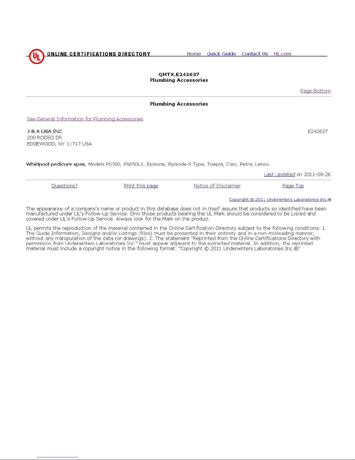
UL Certificate
Back Flow Prevention Device (Dual Check valve)
Limited Warranty
Page 3

Introduction
Thank you for choosing EPISODE LX series , This finest Whirlpool Pedicure Spa has been develop and Manufactured by
J&A USA Inc., to bring quality and exquisitely balanced design yet afford-ability and dependability when properly use.
Please read this entire manual thoroughly before installation and use
PLEASE TAKE TIME TO READ THIS MANUAL THOROUGHLY BEFORE USE. If you have any questions or
concerning with our pedicure spa, Please contact our customer service and technical support at 631-243-3336 ext 121,
Monday through Friday 9AM - 5PM or email us at [email protected]
Important requirements
The MFG requires that you contact your local, licensed plumber and licensed electrician to install your new spa. Installation MUST
be in compliance with all local and state building codes. Your pedicure spa can not operate efficiently or safely unless it is provided
with adequate electrical power, sufficient water pressure, proper water temperature, and required drainage capabilities. Contact your
local building inspector for information and local code compliance procedure that need to be followed when having your new pedicure
spa installed. Subsequent inspections and approvals that may be required are the responsibility of the purchaser.
Shipment Inspection
Examine the components immediately upon arrival to make sure no damages to the pedicure spa base and chair during the shipment. It
is very important that you notify the driver directly and notation should be on the face of the freight bill or bill of lading of any
damage. Failure to note damage on the bill of lading may prevent any claims you may have against the carrier.
If concealed or damage is found, you MUST notify the carrier at once and request an inspection. DO NOT DISCARD THE
SHIPPING CARTON If receiver sign the carrier clean receipt of goods that have been damaged in transit .Do so at your own risk
and expense.
Precaution
- Do not stand in the basin of the spa.
- Excessive water temperature is dangerous and should be checked before use. Maximum water Temperature should not exceed
100F (38C).
- Always enter and exit the spa slowly and carefully.
- Never bring or operate any electrical device near pedicure spa.
- The unit has a weight capacity of 250 pounds.
Health Warning
Individuals whose feet or legs are inflamed or have open wounds should not be allowed to use the pedicure spa at any time. The
technician should advise clients to consult their physician before using the spa if there is any sign of fungal infection, swelling,
fracture, or persistent pain. In some cases diabetics may experience improved circulation in their feet, but should first consult their
physician prior to receiving a pedicure.
If the client experiences any pain or discomfort, discontinue the use of the pedicure spa
immediately.
Page 4
EPISODE
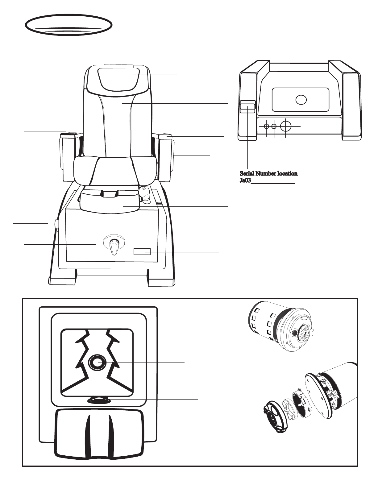
Identification
Remote control
(insert into arm)
LX
Head Rest
Pillow
Backrest
Up/Down Armrest
Arm Tray
Drain Knob
Faucet
Basin
Accentuate Spa Base
Adjustable footrest
Product Logo
Drain Plug
J&
Standard Pipless Motor
(D3)
A
S
A U
Jet cover
Adjustable Footrest
Optional Pipeless Motor
(MG)
Page 5
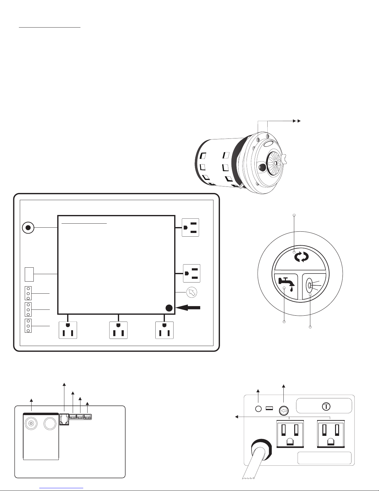
Auto Fill System
(As an optional Only available on Episode LX)
Features & Operation
a. Automatic spa fill with intelligent and reliable level sensor
b. Time delay setting
c. Dual Switched outlets / Control Box
d. Dual continuous outlets
e. Single Drain pump controlled outlet with 3 minute timer ( If drain pump requested as an Option)
f. Heavy duty water valve
g. Operated in automatic or manual mode
h. Automatically shutdown Jet and LED light If water level in the basin is below the sensor
I. Built in LED light power supply
j. Built-in 1 hour timer
k. Audible overflow warning in manual fill mode
SA
U
A
J&
Dura Jet III Built -in
Electrodes Water sensor
KEY PAD
LEVEL
SENSOR
WATER
VALVE
12 VAC
LIGHT
Drain Air Switch
INSTRUCTION
Water Faucet MUST be ON and desirable Temperature
must be set with Faucet handle before using Auto-fill System
1- Pressing the iFill - Auto button will fill the basin with
water automatically.
Water valve will shutoff when water level is above the
sensor.
2- Pressing the JET button will turn On/Off the JET and
LED light manually.
3- Pressing the valve button will turn On/Off the water
manually.
POWER
LED
DRAIN (2A)
Key Pad
Level Sensor
Water Valve
12 AC Light
JET (2A)LIGHT (2A)
CONT (2A)
CONT (2A)
iFILL DELAY
SETTING
POWER
CORD
Power On Indicator
Continuous
Outlet (2 Amp)
Press iFill - Auto to start fill the basin
and once reaches water level
Whirlpool / light will be activated
iFill-Auto
Manual On/Off Water
Time delay setting
Manual On/Off Switch
for Jet & Light
Auto Fill
Delay
Setting
30
5 S
55 S
ALL WIRES ARE INDICATED AS IT SHOWN
Power Cord
Model: L0903A
Voltage: 120 VAC / 60 Hz
Product of USA
Page 6
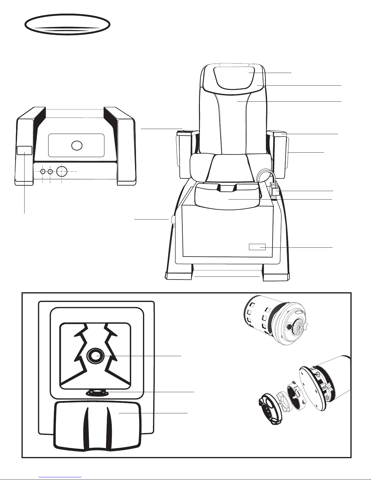
EPISODE
Identification
LXP
Head Rest
Pillow
Backrest
Remote control
(insert into arm)
Up/Down Armrest
Arm Tray
Faucet
Adjustable footrest
Serial Number location
Serial Number location
Ja03______________
Ja03______________
Basin
Drain Knob
Accentuate Spa Base
Drain Plug
J&
Standard Pipless Motor
(D3)
Product Logo
A
S
A U
Jet cover
Adjustable Footrest
Optional Pipeless Motor
(MG)
Page 7

Important Considerations
Electrical Service
110V, 60Hz, 15Amp GFCI protected grounded circuit MUST be used to supply power each individual pedicure spa.
And the main circuit breaker MUST be at 25Amp. For maximum of two units per each electrical outlet.
Water Supply
All plumbing connections must conform to local codes.
Water supply to the spa should be provided with adequate water pressure and water temperature.
Water pressure
To fill the basin correctly up to level, Normal water pressure of 30 to 80 P.S.I is required.
Water temperature
The hot water supply temperature must not exceed 140 . Adjust your hot water accordingly. For hot and cold water supply
fittings and drain fittings location, see below diagram .Carefully connect the water supply line to the appropriate fittings
located on the rear of the pedicure spa.
Pressure / Temperature
Maximum Pressure: 150 psi (10 bars)
Minimum Pressure: 10 psi (69kPa)
Working Temperature: 33F to 140F constant; intermittent to 180f
(0.6C to 60C sustained; intermittent to 82.2C)
Maximum Recommended Flow: 15gpm (571pm)
Backflow Preventive Device (Dual Check Valve)
All J&A pedicure spas are equipped with Back flow Preventive Device Dual Check Valve as standard.
Specification
Tested and certified to meet ANSI/ASSE standard 1024. CSA certified to standard No.B64.6
ANSI - American National Institute, ASME - American Society of Mechanical Engineers, CSA - Canadian Standard
Association IAPMO - International Association of Plumbing and Mechanical Officials, UL - Underwriters Laboratory
** Vaccum Breaker
Due to Town and / or State requirement/s are varies in building code, if the Town and / or State requires
Vaccum Breaker, As the Plumber MUST provide Vaccum Breaker according to building code
requirement.
Drain Facilities
The pedicure spa Drain must meet local plumbing codes. Check valve for Drain (not Provided) Must be installed by a licensed
plumber. Also Pedicure spa must be securely fasten to the floor.
Installation Summary
The installation must comply with local, state, and federal buildi ng, plumbing and e lectrical codes, where applicable. A
licensed plumber should complete the plumbing of the pedicure spa.
Note: Failure to comply with federal, state, or local codes and ordinances will result i n warranty being n ullified and
void.
Page 8
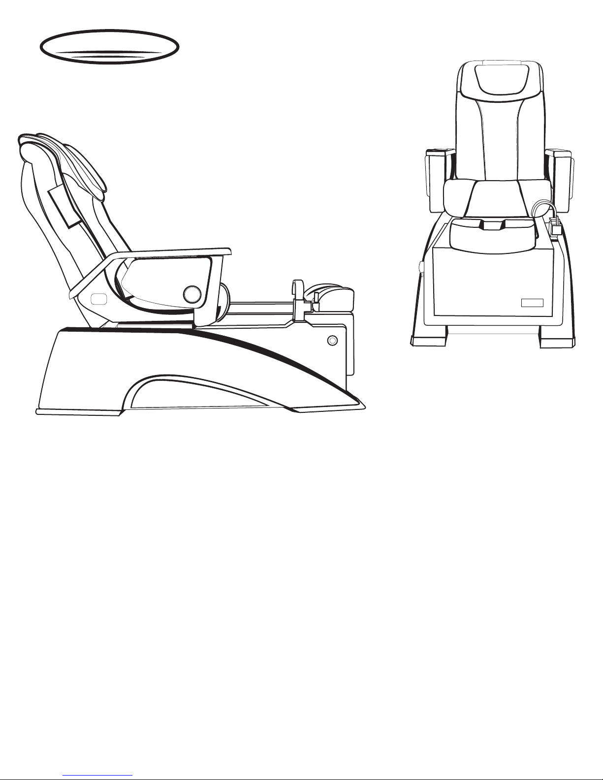
EPISODE
Specification
LX / LXP
Specification
Dimen sion & Weight (Sh ipping)
Dimen sion & Weight (Ne t)
Capac ity of Tub
Switc h
Power S ource
Plumb ing Source
War ranty
Due to continuous improvements on all our products, specification, characteristics, packing, color, designs are subject to
Pedic ure Spa & Mass age Chair
Stool
Pedic ure Spa & Mass age Chair
Episo de LX
Dedic ated 15Amp Wall Outl et Re quire
Pipe - le ss whirlpo ol motor
Disch arge Pump (O ptional)
Massa ge System
Hot Water
Cold Water
Drain
Unit
Optio nal Item
change without notice.
67L x 37W x 40H 242 lbs
20.25 L x 8.5H x 20W 1 9 lbs
57 3/4” L x 28”W x 56” H 182 l bs.
4.5 U.S G allon
On / Off Air Activ ated Switc h
120Vac, 0.4 Am p. 60Hz,
120Vac, 60H z
120Vac, 60H z
0.5 inc hes (Fitti ng Provide d)
0.5 inc hes (Fitti ng Provide d)
1.5 inc hes (See Plu mbing Inst ruc tion)
One Yea r
120 Day s
Page 9
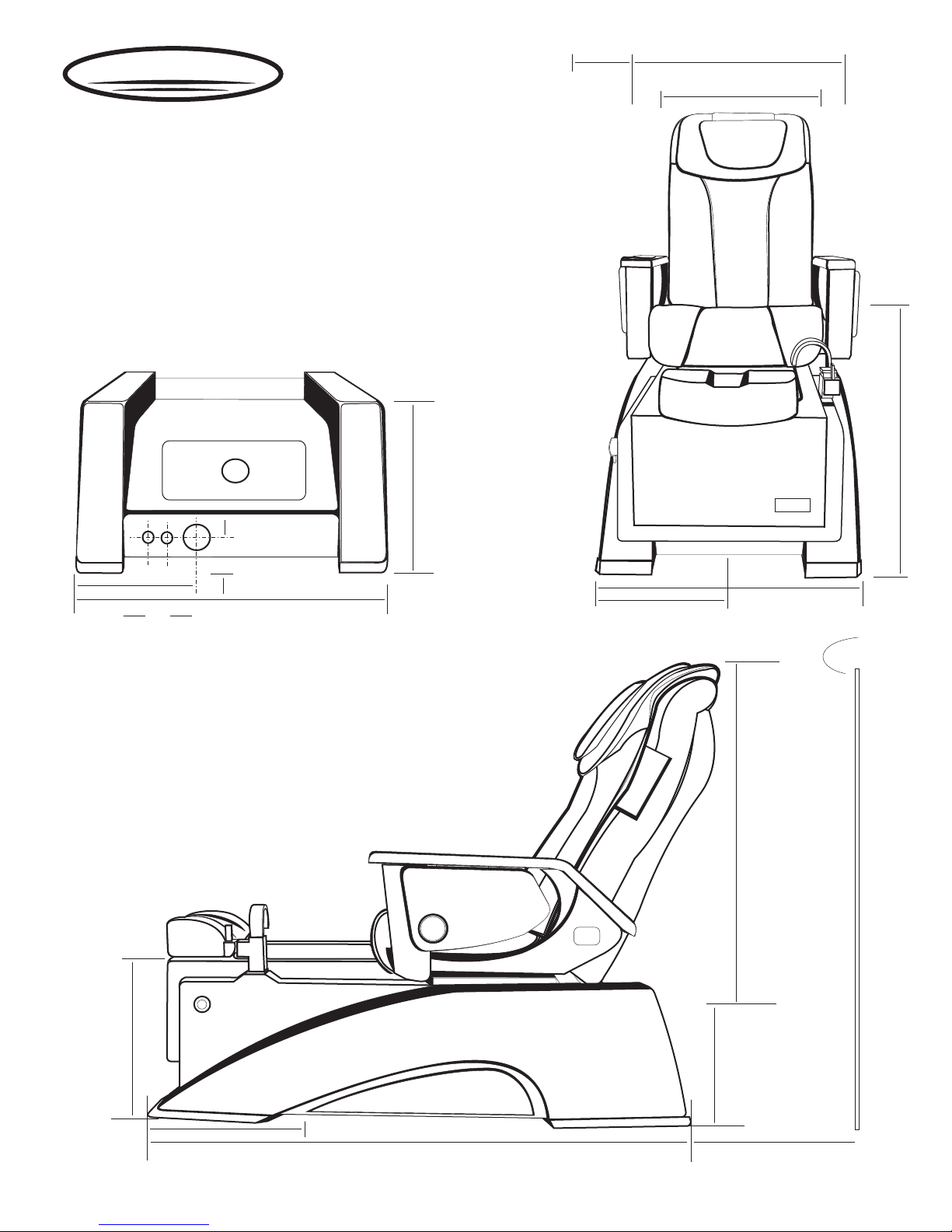
EPISODE
Dimension
LX / LXP
15”
Open Tray
8 ½”
Arm to Arm
28 1/4”
21 1/4”
23 ½”
12”
2”
2 3/4”
28”
26 1/4”
13 1/8”
Wall
43 ½”
16”
15 ½”
57 3/4”
12 ½”
16 ½”
Page 10
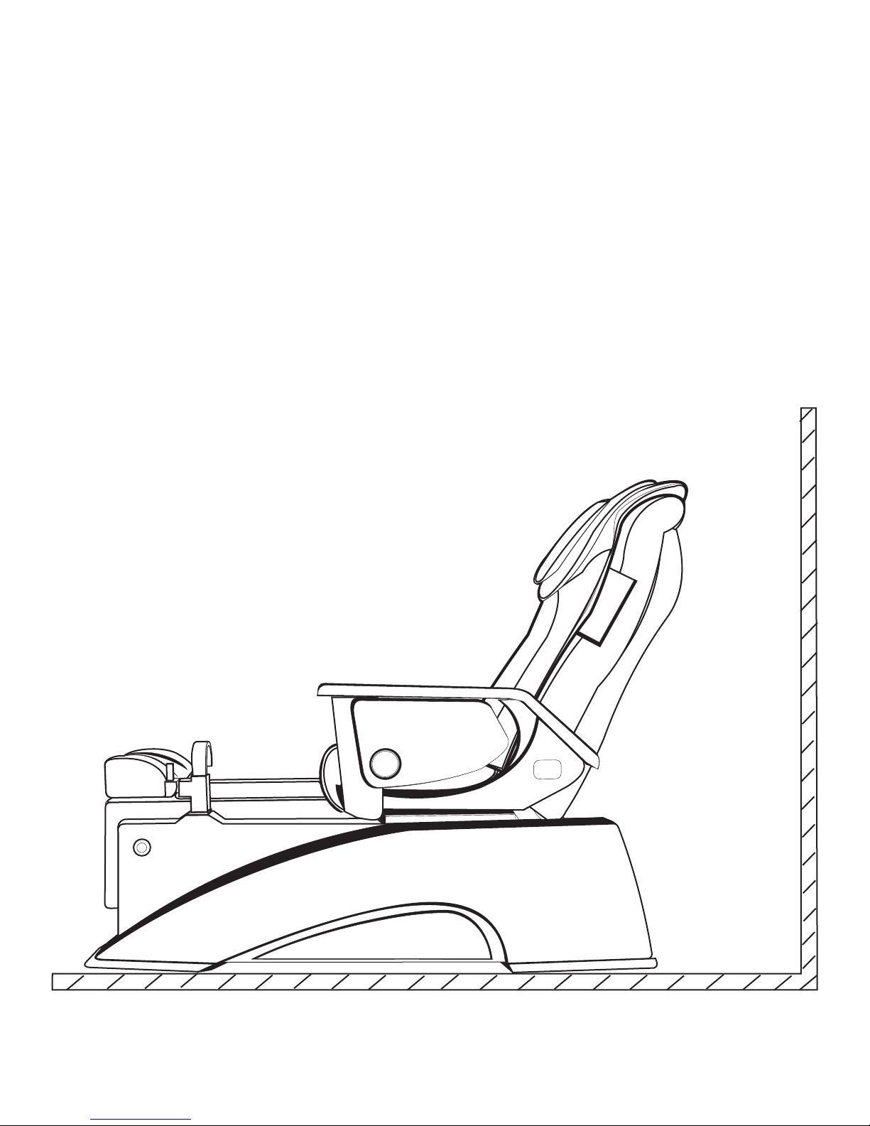
Installation Specifications Summary
Warning: Failure to comply with federal, state or local codes and ordinances will result in warranty being null and void.
As stated, the pedicure spa installation must comply with all plumbing and electrical codes. A licensed plumber and
licensed electrician MUST complete the applicable connections of the pedicure spa.
Location and support
Select a level location. The floor structure beneath the pedicure spa must be capable of supporting the occupied pedicure
spa.
Due to continuous improvements on all our products, specification, characteristics, packing, color, designs are subject to
See Detailed info
on top of the page
change without notice.
Page 11
EPISODE
LX
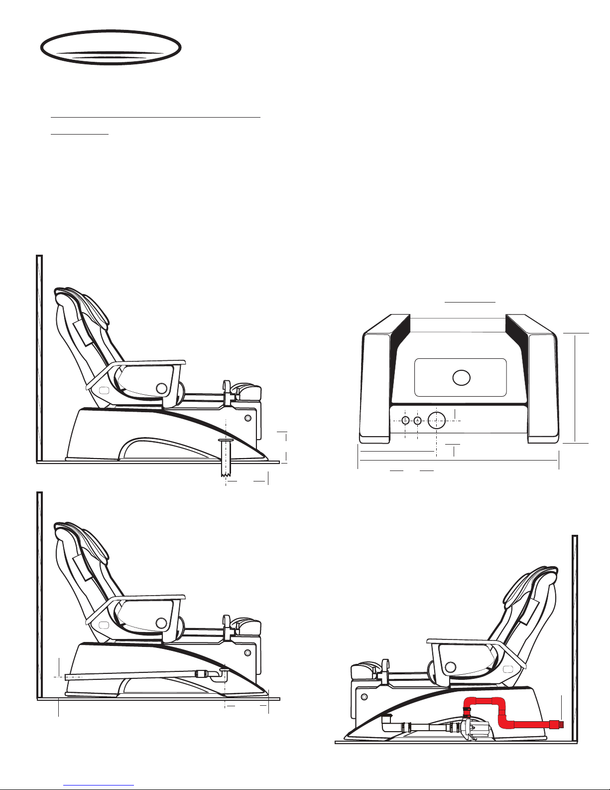
DRAIN
Back Flow Prevention Device (Dual Check Valve)
Specification
Device Name
Device MFG
Device Model
Device Spec.
Device Pressure
Device Temp.
All J&A USA Inc. Pedicure spa is/are equipped with Back Flow Prevention Device (Dual
Check Valve) as standard.
Dual Check Valve Backflow Preventor
WATTS Regulator Company / North Andover, MA
WATTS 3/8 7, 7C and 3/4 H7, H7C
ANSI/ASSE Standard 1024 & 1032, CSA Certified NO.B64.6
Max, minimum pressure 150 psi. - 10 psi, Recommended Flow 10 gpm
33F - 144F Consistent; Intermittent to 180F
Basement Connection
(NOT recommended
on floor drain)
Rear View
Wall drain
15 ½”
15”
2 3/4”
12”
28”
2”
Power Drain
(See detailed power drain pump)
2 3/4”
½”Drain
outlet
15 ½”
Page 12
Dura-Jet III
Safety Instructions
When using electrical equipment, basic safety precaut ions should alwa ys be followed to reduce the
risk of fire, electrical shock, and injury to persons, including the follow ing:
1. Read and follow all instructions before using the equipment.
2. Keep the cord out of heavy traffic area. To av oid fire hazard NE VER put the cord und er the rugs, near he at generating
devices.
3. Always turn off the equipment be fore servicing .
4. Do not drop or insert any object into any openings.
5. Do not operate any equipment with a damage parts.
6. Any other use not re commended by the manufacturer may electrical shock or injury to persons.
7. Never use outdoors
8. Do not attempt to repair or adjust any electrical or mechanical funct ions on the unit.
A
US
A
&
J
Feature
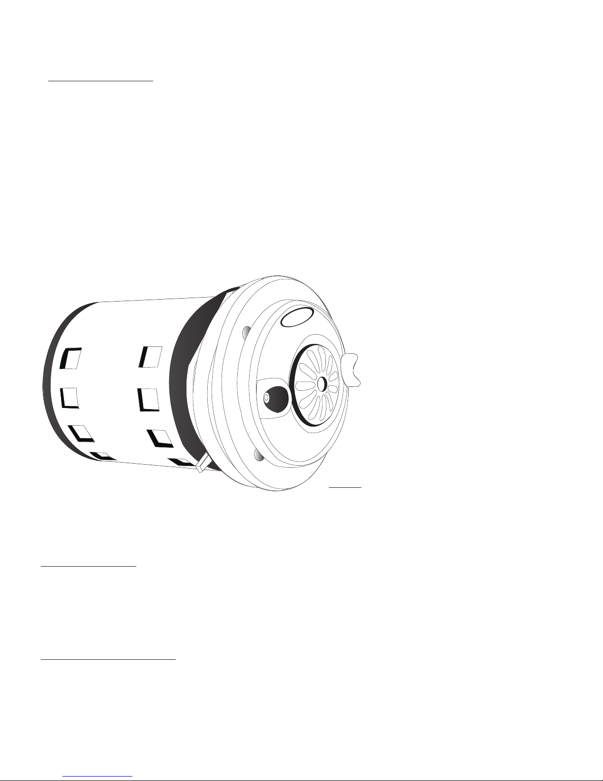
1. Dual powerful massage jet-streams
2. Jet assembly can be attached from the pump for
quick cleaning and sanitizing.
3. Built-in electronic sensor for pump control.
4. AC motor (long lif e)
5. Extremely low power consumption .
Cleaning Instruction
1. Ensure the unit is off
2. Remove the front cover
3. Remove the impeller and impeller cover
4. Use anti-bacterial solution ( EPA registered) to c lean all plastic parts.
5. Reassemble the front cover
DURA-JET III Specific ations
Model: DURA_JETIII -
120Vac, 0.4 Amp. 60Hz,
Pump: Dual Air Jet Fl ow
Mounting: Single 3.5” hole
Auto tighten Moun ting screws(4)
6. Manufactured in USA.
Page 13
When us ing electr ical equip ment, Basi c safety precau tions must b e followed t o red uce the risk o f fire, electri cal shock, a nd
injur y to Persons .
1. Read a nd follow al l instruct ions befor e using the eq uipment.
2. Keep e lectrica l cord out of he avy traffic area. To avoid fire hazard NEVER place elec trical cor d under the ru g, near heat
Gener ating devi ces.
3. Always turn power off the equipment before service.
4. Do not d rop or inser t any object i nto any open ings.
5. Do not o perate any e quipment w ith damage d parts.
6. Any other use not recommended by the manufacturer may cause electrical shock or cause injury to person/s.
7. Neve r use it outdo ors
8. Do not a ttempt to re pair or adju st any elect rical or mechanical.
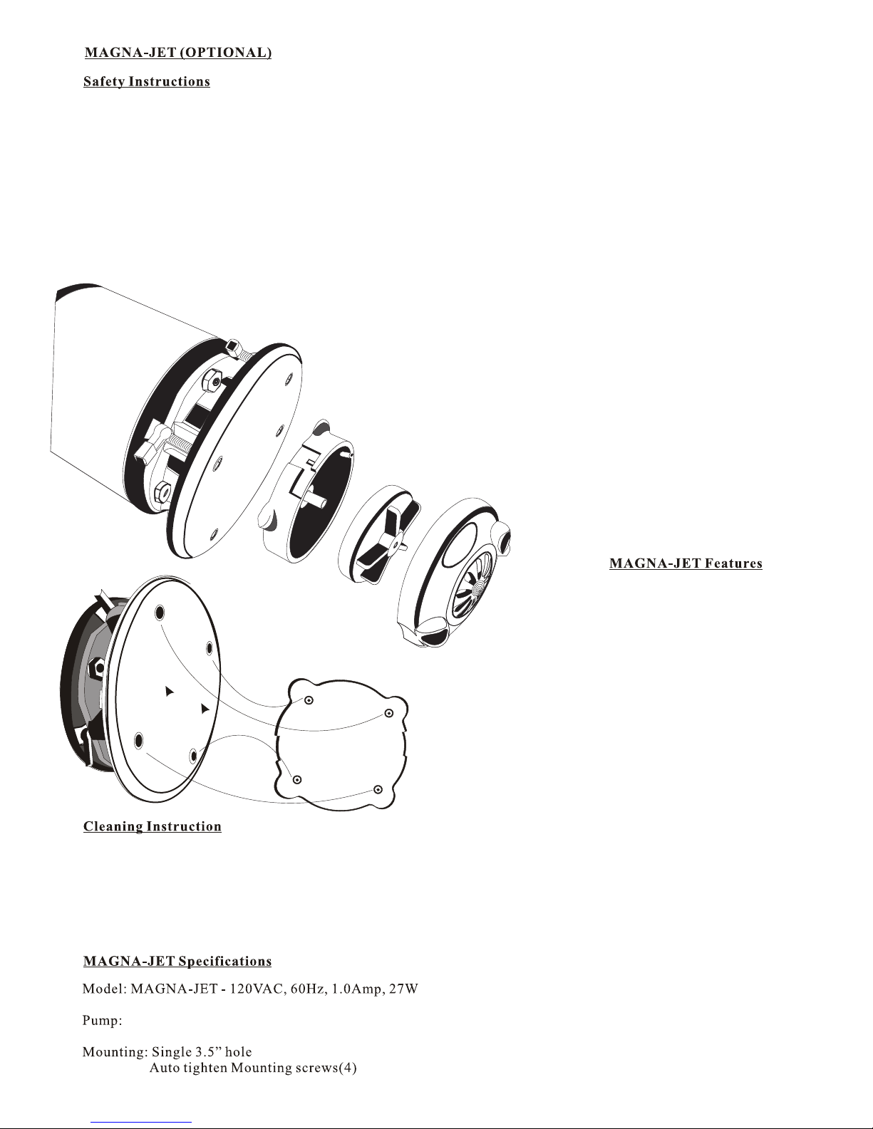
Motor
Round
Magne tic Field (h ousing)
Magne tic
Jet Bas e
Magne tic
Impel ler
Magne tic
Whirl pool jet cov er
1. Hydr o dual massa ge jet strea m
2. Magn etic whirl pool jet cov er can be remo ve for quick
clean ing and sani tizing.
3. Buil t-In elect ronic sens or for pump co ntrol.
4. AC Whirlpool motor (long life)
5. Very l ow power con sumption ( 27W)
6. Manu factured i n USA.
1. Turn off the unit and wait until the motor is fully stops.
2. Hold H ydro whirl pool jet cov er firmly an d pull to sepa rate from th e round magn etic field.
3. Turn hydro whirlpool jet cover to left to open and pull out impeller.
4. Use Anti - Bacterial solution (EPA Registered) to clean all parts.
5. After sanitize all parts, place impeller and close hydro whirlpool jet cover to turn right to lo ck
6. Hold f irmly the wh irlpool co ver jet and ge ntly place i t onto the round magnetic field. Do not release the hydro whirlpool jet cover until
Jet cov er is on the rou nd magneti c housing.
Hydro -Massage D ual jet Flow
Diame ter
Page 14
How to USE Magnetic jet !
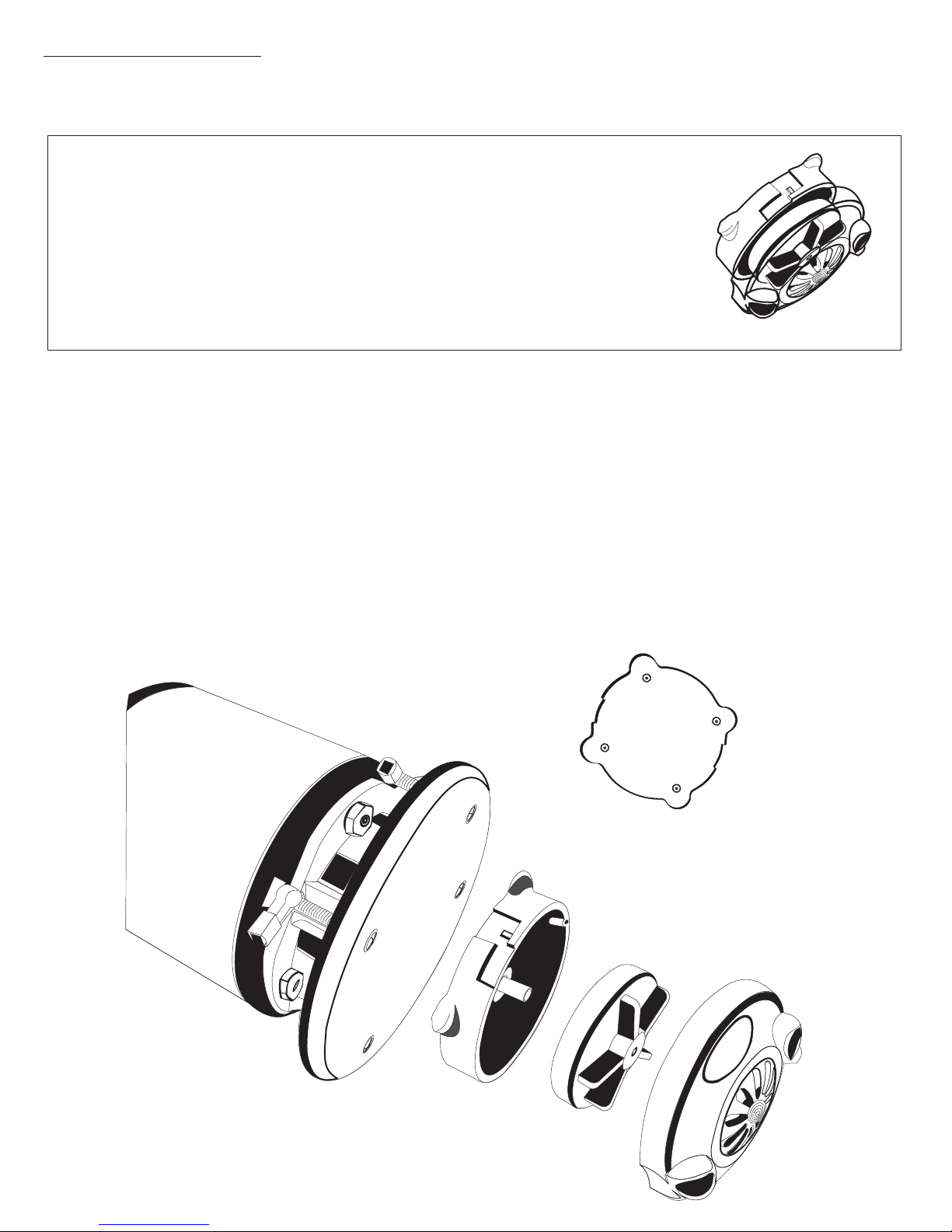
WARNING: DO N OT RU N DRY, BASIN MU ST FI LLED WITH WATER TO LEVEL INDICATOR.
CAUTI ON: MAGNET IC JET COVER ASSEM BLY MUST A LIGN WITH DISCH ARGE PORT
POSIT IONED AT 3/9 O’CL OCK.
WHEN RE ADY TO USE, MAKE S URE JET COVER IS PO SITIONED AT 3 /9 OCLOC K FOR
PROPE R WHI RLPOOL ACTI ON IN THE BASIN. IF J ET CO VER IS NOT ALIGN AT 3/9 O’CLOC K,
WATER WILL SPLASH OUT SIDE OF THE BASIN .
PROPER WAY TO USE MAGNETIC JET SYSTEM
1- FILL THE WATER TO WATER LEVEL INDICATOR.
2- HOLD MAGNETIC JET FIRMLY TO BRING CLOSER TO THE ROUND MAGNETIC FILED AND DO NOT RELEASE
THE MAGNETIC JET PREM ATURELY OR THIS WILL CAUSE IMPACTS ON THE J ET COVER AND THE ROUND
MAGNETIC FIELD(HOUSING) SHORTENING THE LIFE E XPECTANCY OF THE JET COVER . WHEN THE JET
COVER NEARS THE ROUND MAG NETIC FIELD, PLA CE JET COVER ONTO THE FOUR DIMMPLE AREA (SEE
DIAGRAM). THE JET COV ER MUST ALIGN WITH DI SCHARGE PORTS POSITIONED AT 3/9 O’CLOCK.
3- WHEN FINISHED WITH C LIENT, DO NOT REMOVE MAGNETIC JET UNTIL MO TOR IS FULLY STOPPE D.
4- WHEN MOTOR IS FULLY STOPPED, R EMOVE MAGNETIC J ET COVER FROM THE MOTOR AND REMOVE JET
COVER A ND IMPELLER FOR SANITIZATION.
Motor
Bottom View of
Magnetic Jet Base
Magne tic
Jet Bas e
Magne tic
Impel ler
Magne tic
Whirl pool jet cov er
Round
Magne tic Field (h ousing)
Page 15
EPISODE
LX
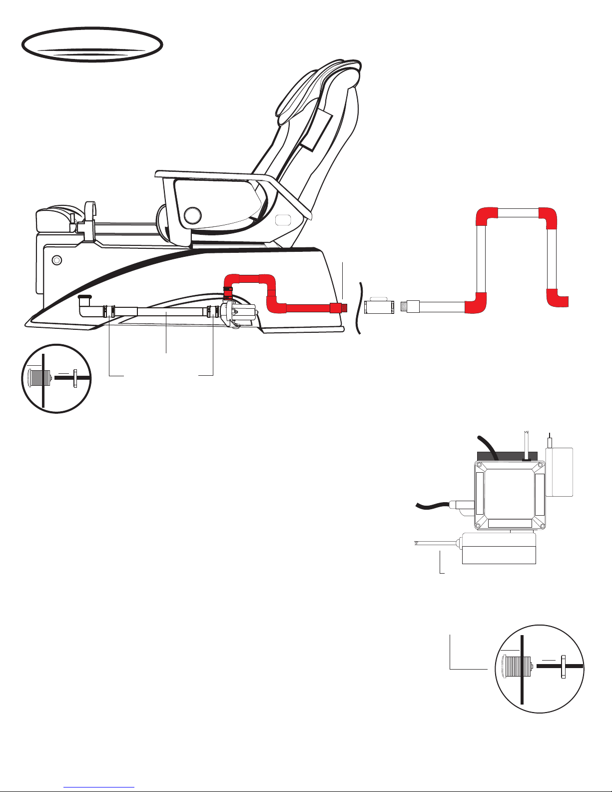
Discharge Pump
½” Discharge Outlet.
1” PCV Pipe
Fastner
1 1/4” x 1 1/4” connector
On/Off
Switch
Installation Instruction
1. Make a hole ( size 1-3/8”) for the On/Off switch as shown (see fig 1). Pre-
drill required.
2. Placed a 1/8” clear hose into the rear of the switch and on/off switch into the
hole.
3. The discharge pump kit is made to fit onto the pedicure unit. (see fig 2)
4. Connect E-Z connector onto the drain elbow.
5. Plug discharge pump outlet into the two minute timer outlet
6. Plug two minute timer into the wall outlet.
7. It is very important that tip of the clear tub remain above the water Level with
one loop as shown.
Max. Drainage height : 4ft.
DRAIN OUTLET MUST BE ½”
or 3/4” FOR EFFICIENT DRAINAGE.
½”X ½” Brass
Check Valve
PLUMBER MUST BE UTILIZED TO INSTALL
CHECK VALVE and Utility Valves for Hot / Cold Water
Electrical Con tro l Box
(Located left bo tto m
inside of base)
3/8” clear Tube
from On/Off Swi tch
Power Plug
for Part time control bo x
to wall outlet
Pipeless Motor
Power Plug
IME
T T
R
A
P
FUL L TIM E
2 Min.Timer
(D.pump)
Lig
Tra
n
h
sf
t
or
P
A
me
RT
TI
r
M
E
** Please cut to fit 1” Flex hose to your size**
Operation Instruction
Warning ! DO NOT RUN DRY
1. Turn to open drain plug. 3 to 5 second for air to release from the pipe
2. Press On/Off switch to activate timer.
3. At any time, water drain completely from the basin. Press
On/Off switch to stop or built in two minute timer.
3/8” Clear Tube from on/off for D/P pump
insert into 2 Min. Timer.
Make sure to push in tightly.
1-3/8” Hole
for On/Off Switch
Figure 1
Fastner
On/Off
Switch
Page 16
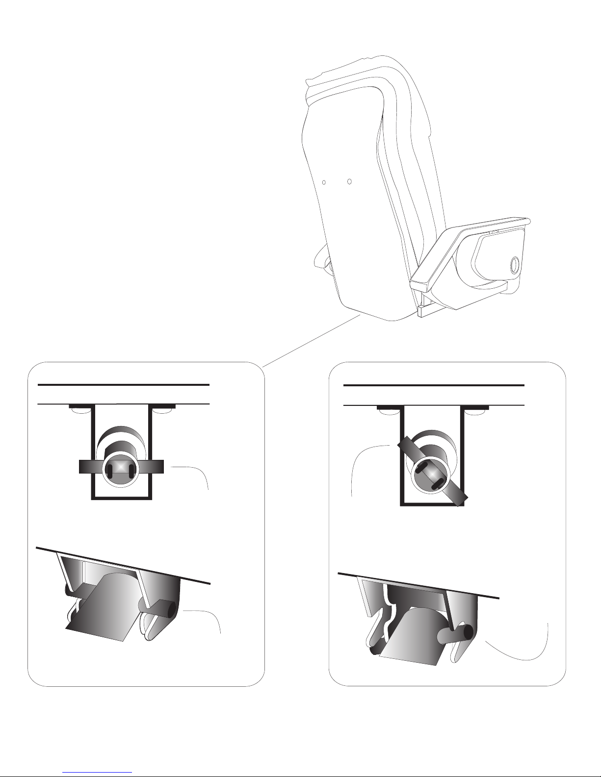
Recliner Piston End Attachment Instruction
CORRECT PIN POSITION
Recliner
Piston Pin
BOTTOM OF BRACKET
Recliner Piston Located
WRONG PIN POSITION
Recliner
Piston Pin
BOTTOM OF BRACKET
A. PLEASE MAKE SURE PIN LOCATED AT THE END OF RECLINER PISTON IS IN HORIZONTAL POSITION.
B. SLOWLY BRING UP THE BACKREST TO UP RIGHT POSITION UNTIL YOU HEAR “CLICKING” SOUND TO
ENSURE PROPER PIN ENGAGEMENT INTO LOCKING LATCH.
Locking
Latch
Locking
Latch
Page 17
EPISODE
LX
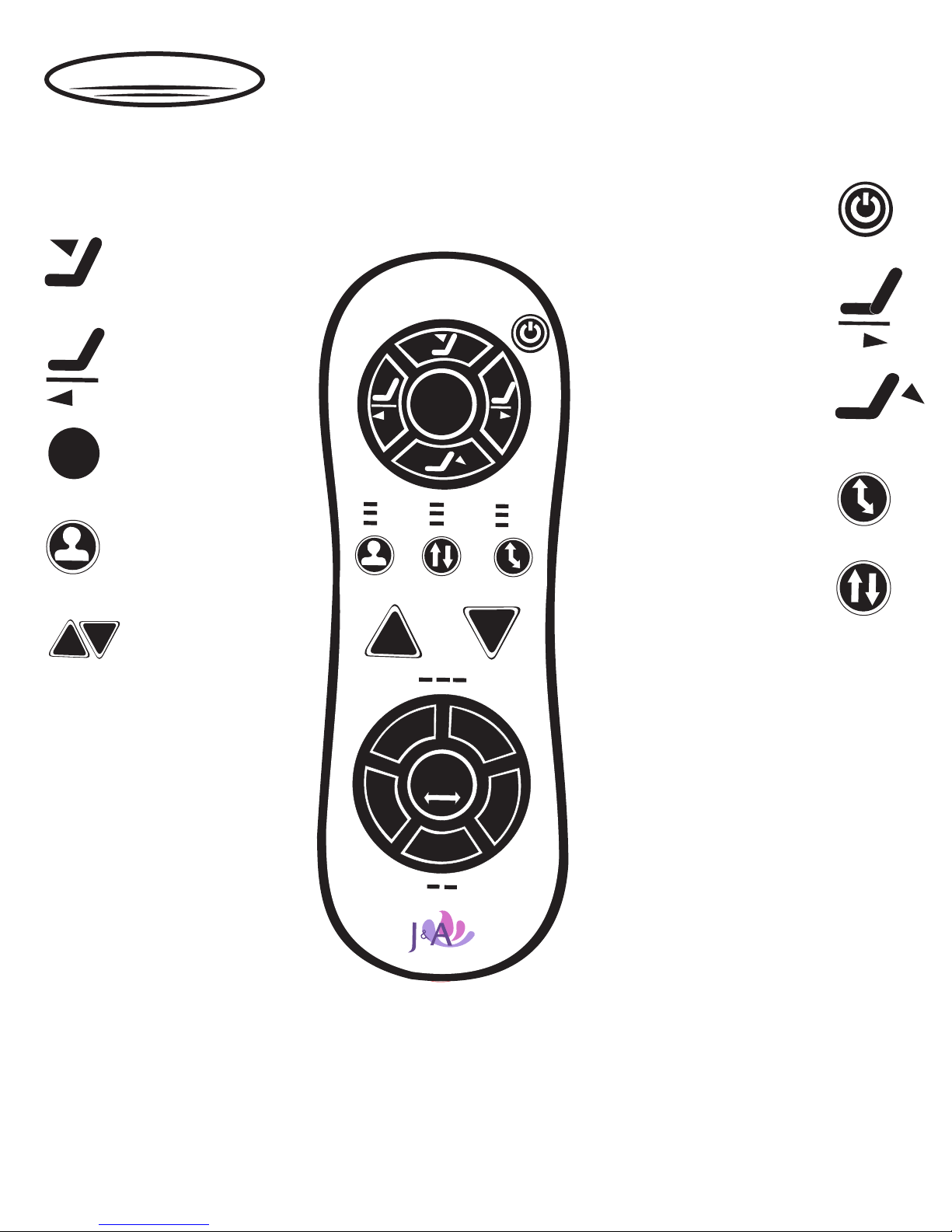
Remote Control Functions
INCLINE
Press down to move chair
To desirable angle.
FORWARD
Press to hold to move
chair to desirable position
AUTO
AUTO
UP
KNEADING
3 Selections of Kneading Intensity
KNOCKING
Impulse Tapping Massage.
2 Selections of Knocking Intensity
Pre-Programed Automatic
Massage with 2 Selection
POSITION
User’s Height
(HIGH / MID / LOW)
WHEEL
DN
Adjust Massage Wheels
Up and Down to desirable
position.
POSITION
MASSGAE
VIBRATION
HIGH
MID
LOW
UP
KNEAD
KNOCK
AUTO
FULL
PAR
SPOT
RANGE
WHEEL
MSG
WIDTH
V
I
B
TIAL
DN
INTENSITY
COMB
INTENSITY
30
20
10
MANUAL
TAP
POWER
On / Off
BACKWARD
Press to hold to move
chair to desirable position
RECLINE
Press down to move chair
To desirable angle.
MANUAL
Press for Manual MODE with
Time Selection of 10~30 Mins.
RANGE
FULL / PARTIAL / SPOT
3 Selections
MSG
Keep Pressing to Massage Wheel
to the intended Massage Width.
COMB
Kneading / Tapping / Knocking
Combinations
TAP
3 Slections of Tapping intensity
VIB
2 Selections of Intensity for Seat
vibration Massage.
SHIATSU
1. Press Manual / Timer to choose
Shiatsu Massage Time Selection
2. Press Massage Range to Select
FULL or PARTIAL Travel
Position.
3. Press Tapping Width to fine
tunecomfort.
Page 18
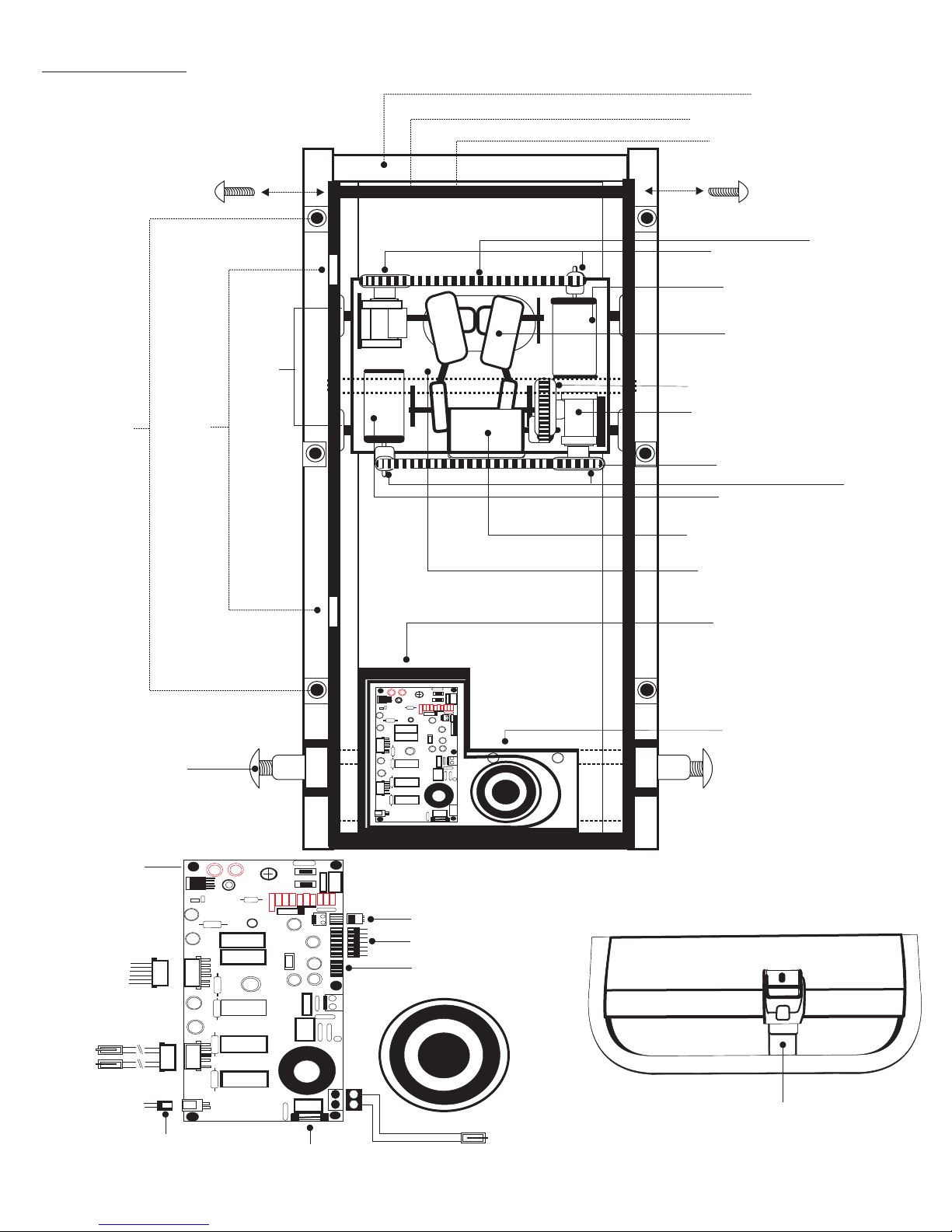
Massage Mechanism (TGX)
Back cover Open View
Phillip Screws
Chair Main Frame
Massage Mechanism Frame
Mechanism Limited frame Bar
Massage Mechanism
Frame Fasteners
(3 /ea. side)
Mechanism Track
Guide Roller
Travel Signal
Sensor
Belt Pulley
DC Motor (Kneading)
Massage Arm extension
Tapping Belt
Up and Down Gear Box
Travel Belt
DC Motor (Travel)
DC Motor (Tapping)
Rod w/ ball extension
CASED Main PCB
Kneading Belt
Belt Pulley
Backrest Pivot Fastener
Board Holders
D/C Motors
Red (Recliner)
White (Slider)
Vibration(Grn/Yel)
Power Converter
Travel Sensor
Remote Control
Blank
Bracket For Recline Piston
Power
PCB Fuse
Page 19

DISINFECTING YOUR PEDICURE SPA
Note: Please be advised that it is responsibility of purchaser/user to adhere strictly to the following procedure.
Any non-compliance will be considered negligence of the purchaser/user.
The Bureau of barbering and cosmetology requires that salons using whirlpool pedicure spas use the following disinfecting
Procedures to ensure proper cleaning and maintenance of the equipment, and to prevent bacterial infection. For your clients
safety, always use the regulations as a minimum standard for cleaning and disinfecting.
Chair maintenance
Please see chair manual for Do and Don't
At the end of the day:
1. Remove the intake suction screen, All debris trapped behind the screen of each pedicure spa must be removed.
And the screen and the inlet shall be washed with soap or detergent and water
2. Before replacing the screen, Totally immersed the screen into an EPA- registered disinfectant with bactericidal,
Fungicidal, and virucidal activity.
3. Finally, flush the whirlpool system with low-suding detergent and warm OR an EPA - registered cleanser for
10 minutes. Rinse with clean fresh water and drain.
Note:
Cleaning or sanitizing is NOT disinfecting. According to the CDC and EPA, disinfecting occours only when there is a
reduction of pathogenic microbes at 99.999%. Sanitizing is a only reduction of 99.9%. Cleaning of whirlpool pedicure spa
requires surfactant and chelating detergents that are low foaming and have ability to remove body oils, organic oil
additives, mineral oil, skin cell, nail clippings, etc.. that can accumulate both in the basin and the jets which may become
fertile area for micro organism to grow.
Note:
The use of oil based products can build up in the whirlpool system causing clogging in the jet and build up onto the surface
of the basin. Adherence to the above cleaning will minimize build up thus the manufacturer recommend not to use mineral
oil based product.
Page 20

USER RECOMMENDATION
PLEASE READ THE MANUAL THROUGHLY BEFORE USE TO ENSURE CORRECT
OPERATION.
THOSE UNDER A DOCTORS CARE OR WHO ARE EXPERIENCING ONE OR
MORE OF THE FOLLOWING DONDITIONS SHOULD CONSULT THEIR DOCTOR
BEFORE USE.
- You are receiving medical treatment or are feeling ill.
- Your body shows any cute symptoms.
- You have heart disease.
- You are pregnant or having a menstrual period.
- Your doctor has ordered you to rest.
- You have a back disorder resulting from an accident or disease.
- You have a high fever.
- You have sensory disorders.
- You have medical electrical device (e.g. pacemaker).
- You have service interruption in the circulation of the legs.
- You are diabetic.
FAILURE TO DO SO MAY RESULT IN ACCIDENTS AND HEALTH PROBLEMS.
Page 21
Page 22

Back Flow Prevention Device
(Dual Check Valve)
May 1,2007
In accordance with applicable Local or State regulations,
J&A USA Inc., The manufacturer of the pedicure whirlpool spa certifies that the following models are
equipped with factory installed Dual Check Valve back flow preventer:
** Lenox Series
** Cleo Series
** Episode Series
** Pacific Series
** Petra Series
** Toepia Series
The specification of the installed device is as follows:
J&A USA Inc.
335 Crooked Hill Road
Brentwood, NY 11717
Tel: 631.243.3336
Fax: 631.243.3339
www.jausainc.com
DEVICE NAME
DEVICE
MANUFACTURER
DEVICE MODEL
DEVICE
SPECIFICATION
DEVICE
PRESSURE
DEVICE
TEMPERATURE
DUAL CHECK VALVE BACKFLOW PREVENTOR
WATTS REGULATOR COMPANY
NORTH ANDOVER, MA
WATTS 3/8 7, 7C AND 3/4 H7,H7C
TESTED AND CERTIFIED TO MEET ANSI/ASSE
STANDARD 1024 & 1032
CSA CERTIFIED TO STANDARD NO.B64.6
MAXIMUM PRESSURE: 150 PSI (10 BAR)
MINIMUM PRESSURE : 10 PSI (69KPA)
MAXIMUM RECOMMENDED FLOW: 10GPM
WORKING TEMPERATURE:
33F~144F CONSISTENT; INTERMITTENT TO
180F
ALL MODELS OF PEDICURE SPA MENTIONED ABOVE ARE EQUIPPED WITH THE SUBJECT DEVICE
AS STANDARD FEATURE. As for your information, indicated State requires Vaccum Breaker.
** Effective April 01 2005:
ARIZONA, CALIFORNIA, NEBRASKA, NEVADA, OREGON,
TEXAS AND WASHINGTON
** Effective June 15 2005:
ILLINOIS, MINNESOTA, WISCONSIN, MICHIGAN
** Effective May 01 2007:
CONNECTICUT
For additional information, Please contact us at 631-243-3336 ext. 108
Very Truly yours,
Technical Support
Page 23

J&A USA Inc. Limited Warranty
J&A USA Product: Lenox, Episode, Petra, Toepia, Cleo , Pacific
J&A Accessories: Tri-Stool, Euro Stool, Galaxy Stool and Cookie stool
The Original Purchase Receipt is required as a proof of purchase.
Duration of the Limited Warranty for J&A Accessories : 90 Days from date of Purchase
Duration of the Limited Warranty F or Pedicure Spa: One year from date of Purchase
Coverage on Limited Warranty: Part/s & Labor
EPISODE
Extent of Limited Warranty
J&A USA warrants that the J&A Pedicure Spas that you have purchased are free from defects i n material or work manship under
normal use during the Limited Warranty period. The Limited Warranty period starts on the date of purchase. Your will be
required to provide proof of purchase as a condition of receiving warranty service.
During the Limited Warranty period, J&A will, at its sole discretion, repair or replace any defe ctive componen t. All component
parts removed under this Limited Warranty become property of J&A USA Inc.
In the unlikely event that J&A is unable to re pair or provide eq uivalent parts f or defective pro duct covered under the Limited
Warranty, J& A will, at its sole discretion, may elect to provide customer with a replacement u nit of J&A’s choosing that is the
same or equivalent to customer’s J&A Pedicure Spa i n performance OR m ay give customer a refund of the purchased price in
lieu of replacement. Let it be understood that J&A has no obli gation to repair, replace or r efund until the verification process by
J&A USA is deemed complete. J&A USA Inc’s Limited Warranty is valid in the USA where the covered J&A’s Pedicure Spa is
distributed by J&A and its distribu tors.
It is required that serial number be made available when requesting a li mited warranty s ervice. Failur e to do so may result in
“service request” to be categorized as that of “out of warranty” request which as a result , will incur charges to the requester.
Unless otherwise stated, and to the extent permitted by local law, J&A will, at its sole dis cretion, repai r or replace any def ective
component with new or parts equivalent to new. Replacement parts are warranted to be free from defects in material or
workmanship for ninety(90) days or for the reminder of the Limited Warranty period of the J&A’s Pedicure Spa at issue,
whichever is longer.
Warranty Exclusion
J&A USA is not responsibl e for damage that occurs as a result of customer’s fai lure to follow the instructions intended for J&A
Pedicure Spa. The Limited Warranty does not apply to consumable part/s as well as to parts considered “wear & tear” items
such as , but not limited to, whirlpool components, showerhead, impeller, jet covers and does not ex tend to Product wh ich has
(1) been improperly or inadequately maintained or modified (2) been modified in any way or misused (3) been installed / set up on improperly prepared site.
(4) been tampered with in any way such as (a) improper installation (b) usage of re-manufactured or refurbished plumbing component/s. (C) abused, (d)
neglected, (e) Moved from its initial location of the installation, and (f) Subject to faulty maintenance, abuse, misuse, accident or other damages.
The Limited Warranty does not apply to local building code compliance. Since local build ing codes vary con siderably, the
customer must check with a local building or plumbing contractor to en sure the local cod e compliance is me t before
installation. The Limited Warranty applies only to the original purchaser of the J&A produc t.
Limitation of Warranty
TO TH E EXTENT ALLOWED BY LOCAL LAW, NEITHER J&A NOR ITS THIRD PARTY SUPPLIER MAKES ANY
OTHER WARRANTY OR CONDITION OF ANY KIND WHETHER EXPRESSED OR IMPLIED WITH R ESPECT TO THE
J&A PRODUCT AND SPECIFICALLY DISCLAIM THE IMPLIED WARRANTIES OR CONDITIONS OF
MERCHANTABILITY, SATISFACTORY QUALITY, AND FITNESS FOR A PARTICULAR PURPOSE. Some state or provinces
do not allow limitations on the duration of an implied warranty. In th is ca se ab ove l imi tat ion o r exc lus ion m ay no t app ly to y ou. This warranty gives you a
specific legal right that varies from State to State or province to province.
Limitation of liability
TO TH E EXTENT ALLOWED BY LOCAL LAW, EXCEPT FOR THE OBLIGATIONS SPECIF ICALLY SET FORTH I N
THIS WARRANTY STATEMENT, IN NO EVENT WILL J&A OR ITS THIRD PARTY SUPPLIERS BE LIABLE FOR ANY
DAMAGED CAUSED BY J&A’S PEDICU RE SPA OR THE FAILURE OF J&A PEDICURE SPA INCLUDING ANY LOST
PROFIT OR SAVINGS, B USINESS INTERR UPTION, LOSS OF USE OR ANY OTHER CO MMERCIAL OR ECONOMIC
LOSS OF A NY KIND, OR SPECIAL, INCREMENTAL, OR CONSEQUENTIAL DA MAGES. THIS LIMITATION OF
LIABILITY APPLIES WHETHER DAMAGES ARE SOUG HT, OR A CLAIM MADE, UNDER THIS LI MITED
WARRANTY OR AS A TORT CLAIM, A CONTRACT CLAIM OR ANY OTHER CLAIM.
 Loading...