

Izzo Golf tri-daddy-hitting-net User Manual
SET UP INSTRUCTIONS (continued)
step 4
G
L
CC
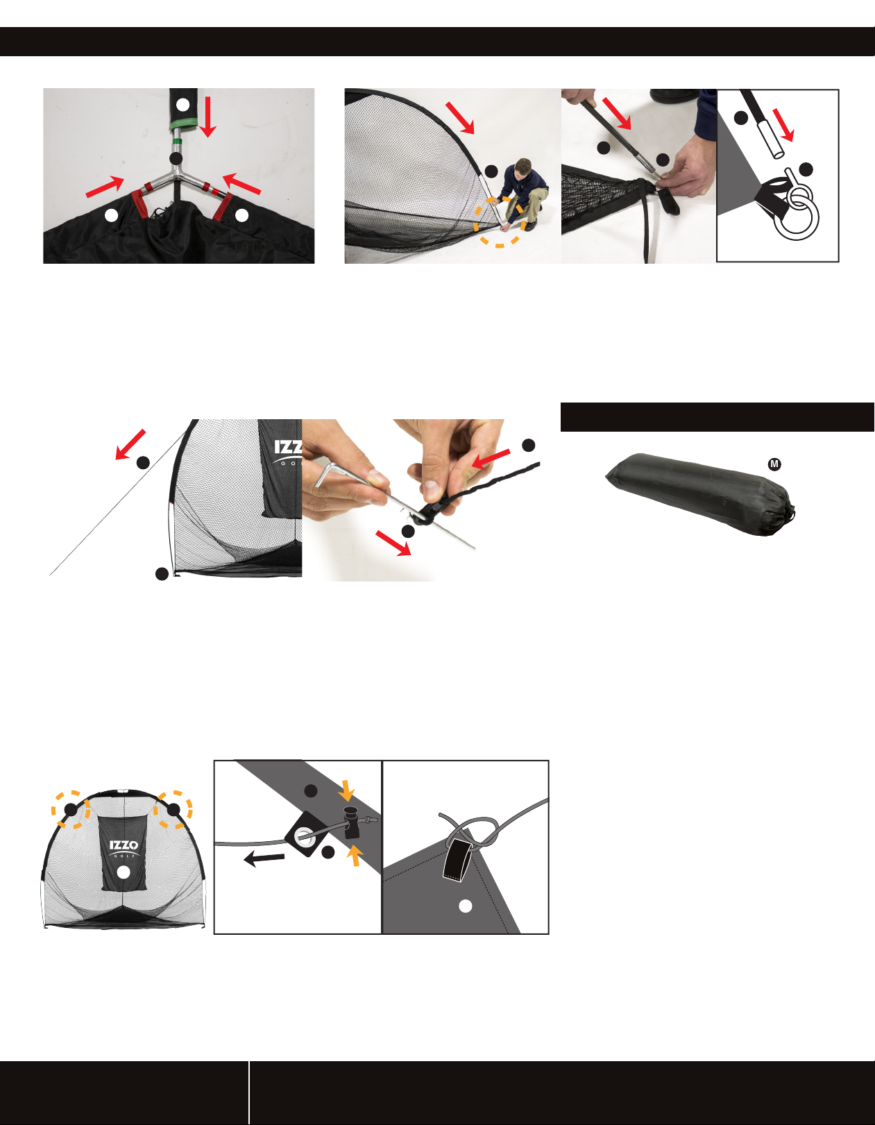
Insert Pole Connector (L) in the center of
Sleeves (C)(G), where Frame Poles meet.
Insert Frame Poles that are in the RED
Sleeves (C) into the RED ends of the Pole
Connector (L). Insert Frame Pole that is in
the GREEN Spine Sleeve (G) into the
GREEN end of the Pole Connector (L).
step 6
F
step 5
I
Image 1
I
I
Image 2
After solid ends of Frame Poles ( I ) are connected to Pole Connector (L).
Firmly grab opposite end of Frame Pole ( I ), arc Frame Pole ( I ) (Image 1) and
insert Corner Pin (H) into hollow end of Frame Pole ( I ) ( Image 2 & 3). Do this
for all three Frame Poles ( I ). Hitting net is now assembled and should be
standing upright. Please refer to Tri-Daddy images on the front of instructions,
above the “KEY” for reference on how hitting net should look standing upright.
STORAGE INSTRUCTIONS
F
H
H
Image 3
M
Image 1
E
K
Image 2
To secure net to ground push Metal Stakes (K) firmly through Anchor Stake
Loops (E) into ground. In order to add extra stability to hitting net, untie Anchor
Stake Draw String (F). Pull opposite end of Anchor Stake Draw String (F) that
has plastic piece attached, at a 45 degree angle away from the hitting net until
draw string is tight (Image 1). Insert Metal Stake (K) through loop of string that
is threaded through plastic piece of Anchor Stake Draw String (F) (Image 2).
Push Metal Stake (K) firmly into ground at a 45 degree angle away from hitting
net (Image 2). To adjust Anchor Stake Draw String (F) length pull plastic piece
attached to Anchor Stake Draw String (F) toward or away from hitting net.
step 7
Image 1
C
D D
D
A
Image 2
Image 3
A
To disassemble Hitting Net, reverse steps
7 through 1.
Uninstall Hitting Target (A) and fold in
1.
order to fit into Carry Case (M). Remove
all Metal Stakes (K) from ground.
Remove all Corner Pins (H) from
2.
Frame Poles ( I ).
Next remove Pole Connector (L) from
3.
all Frame Poles ( I ).
Disassemble shock corded
4.
Frame Poles ( I ).
Fold hitting net up and roll as tight as
5.
possible in order to fit in Carry Case (M).
Place Hitting Net into Carry Case (M).
6.
Add Frame Poles ( I ) to Carry Case (M).
7.
Last Add Metal Stakes (K),
8.
Pole Connector (L) and Hitting
Target (A) to Carry Case (M).
To install the Hitting Target (A), Untie draw strings from Hitting Target (A). Slide cord lock
down toward knotted end of string by squeezing the lock between your thumb and forefinger
to open the string hole shown with the orange arrows above (Image 2). Thread opposite end
of string through Target Grommets (D) shown in orange circles (Image 1 & 2). Tie end of
the string to Hitting Target (A) loops located on the back of Hitting Target (A) in the
corners, use double knot for extra security (Image 3). Repeat steps for other side of Hitting
Target (A). Hitting Target (A) should look as shown (Image 1).
CUSTOMER SERVICE
FOR MORE INFORMATION PLEASE VISIT WWW.IZZO.COM OR CALL 1-800-284-1220
TRI-DADDY™ INSTRUCTIONS
L
D
F
C
I
H
E
I
A
B
D
F F
J
C
I
H
E
I
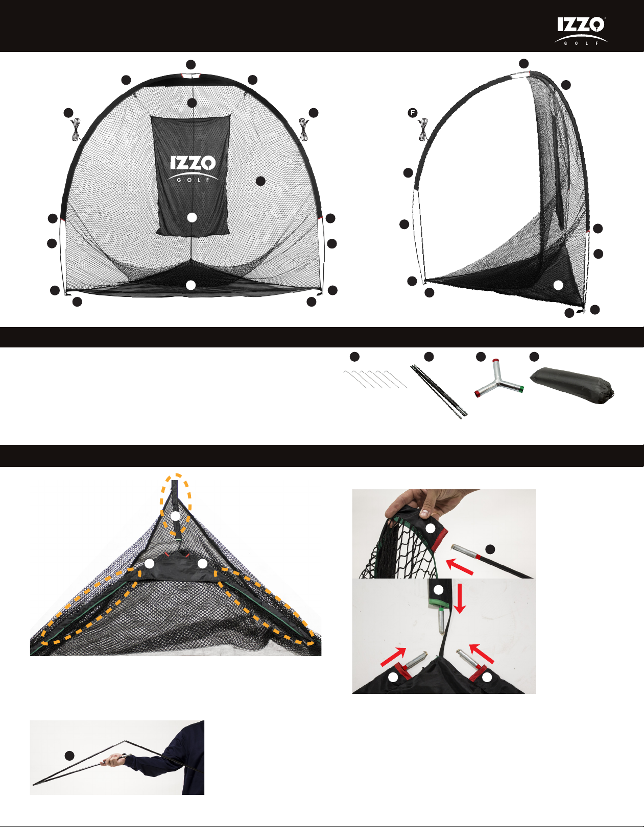
KEY: INCLUDES:
A. Hitting Target
B. Mesh Base
C. Front Pole Sleeves (2)
D. Target Grommets (2)
E. Anchor Stake Loops (3)
F. Anchor Stake Draw Strings (3)
G. Spine Pole Sleeve
H. Corner Pins (3)
I. Frame Poles (3)
J. Hitting Net
K. Stakes (6)
L. Pole Connector
M. Carry Case
K
M
D
G
C
I
H
E
I
L
B
H
E
M
SET UP INSTRUCTIONS
step 1 step 3
G
CC
Unroll hitting net and lay flat on floor. Make sure Sleeves (C)(G)
are on top of net. Align sleeves to form a triangle shape as
shown above in the orange circles.
step 2
I
Assemble all three Frame
Poles ( I ) by interlocking
shock-corded poles.
Slide one Frame Pole ( I ), RED end first, through each of
the opposite ends of the RED marked Pole Sleeves (C),
toward the center of the triangle shape formed in Step 1
(Image 1). You should be able to see both ends of the pole
now. Repeat step for 2nd RED labeled Frame Pole ( I ).
Now insert the GREEN labeled Frame Pole ( I ), GREEN
end first, through the GREEN marked Spine Pole Sleeve
(G) of the hitting net. All color labeled ends of the poles
should meet in the center (Image 2).
C
G
Image 1
I
Image 2Center of Net
CC
 Loading...