


RADAR 24
OPERATIONS MANUAL
3.10 Manual written by Robin Leboe
iZ Technology Corporation
214-8988 Fraserton Court, Burnaby, BC
Phone 800.776.1356 • Fax 604.430.5818


Contents
HOW TO USE THIS MANUAL 7
CONVENTIONS 7
OVERVIEW 8
FRONT PANEL 9
REAR PANEL 10
INSTALLATION 11
MAKING CONNECTIONS 11
A.C. POWER 12
SCSI 12
SYNC REFERENCE 12
AUDIO CABLING 16
TIME CODE 17
SESSION CONTROLLER / KC-24 18
MONITOR (OPTIONAL) 18
RADARLINK 18
ETHERNET 18
MACHINE CONTROL 18
CONFIGURATION 19
OPERATING LEVEL 19
SYNC REFERENCE 20
DIGITAL I/O FORMAT 23
TIME CODE 24
NETWORKING 25
PREFERENCES 29
SOFTWARE 29
OVERVIEW 31
WORK FLOW 31
DISPLAY OVERVIEW 32
RADAR VIEW 33
SESSION CONTROLLER DISPLAY 34
INDICATORS 34
VIEW MANAGEMENT 35
ON SCREEN HELP 36
ENTERING VALUES 37
NUMERIC KEYPAD 37
ARROW KEYS 37
NAVIGATING MENUS 38
MENU/PREV 38
KEYBOARD SHORTCUTS 38
CANCELING A SELECTION 38
MENUS 38
SUB-MENUS 38
DIALOGS 39
DIRECT ACCESS KEYS 39
DISK MANAGEMENT 39
MOUNTING AND UNMOUNTING DISKS 39
SHOW DISK SPACE 40
RECLAIM SPACE 40
ERASE ALL AUDIO 41
DISK MODE 41
DISK DIAGNOSTICS 42
SCAN SCSI BUS 42
INITIALIZE DISK 42
CHECK DISK 43
REPAIR DISK 44
CHECK PROJECT 44
REALTIME ERRORS 44
COPY HARD DISKS 45
VERIFY HARD DISKS 46
CONFIGURE DEBUG 46
SAVE DEBUG 47
PROJECT MANAGEMENT 47
GOTO PROJECT 47
NEW PROJECT 48
COPY PROJECT 48
DELETE PROJECT 48
NAME PROJECT 48
RENUMBER PROJECT 49
TRACK MANAGEMENT 49
NAMING TRACKS 49
FILE MANAGEMENT 50
EXPORT 50

IMPORT 51
BACKUP 51
RESTORE 54
DELETE BACKUPS 55
RECOVER BACKUPS 55
DELETE FOLDER 56
MACROS 56
FILE PREFS 58
FILE TRANSFER 59
DVD-RAM 59
SCSI DISK 60
CIFS SERVER 61
PEER-TO-PEER 62
FTP 63
TRANSPORT OPERATIONS 64
TRANSPORT KEYS 64
JOG/ SHUTTLE WHEEL 65
MOUSE JOG (KC-24 ONLY) 65
AUTO LOCATE MARKERS 66
AUTO PLAY 68
AUTO PUNCH 68
CYCLE 68
PRE ROLL 69
FOOT SWITCHES 69
RECORDING 69
RECORD MODE 69
MONITORING AND TRACK STATUS 70
AUTO PUNCH 71
UNDO/REDO 72
FOOT SWITCH (OPTIONAL) 72
CHASING TIME CODE 72
SYNC / OFFSET 73
CHASE / TC PREF 73
TC CAP (CALC) 74
VARI-SPEED 75
EDITING 77
OVERVIEW 77
THE CLIPBOARD 77
MACRO KEYS 88
QWERTY KEYBOARD 88
RADARLINK 88
MENU TREE OVERVIEW 93
MENU ITEM QUICK REFERENCE 96
REMOTE KEYBOARD KEYS 128
INDEX 142
NOTES 145
EDITING CROSSFADES 78
MARKING A TIME REGION 79
SELECTING TRACKS 80
EDITING FUNCTIONS 80
SOFTWARE VERSIONS 89
ID NUMBERS 89
RADARLINK ENABLE/DISABLE 89
LINK MODE 90
SOLO MODE 90
PROJECT NUMBERS MUST MATCH 92
SYNCHRONIZATION 92
EDITING IN LINK MODE 92
MAIN MENU 96
SYSTEM MENU 96
SYNC MENU 98
DIG I/O MENU 104
FILE MENU 108
PROJECT MENU 110
EDIT MENU 115
PREFERENCES MENU 120
DIAGNOSTICS MENU 126
HELP 127
SHUTDOWN RADAR 128
SESSION CONTROLLER 128
KC-24 KEYBOARD 139

Section
1
Introduction
Welcome to RADAR24, the professional’s choice for multitrack hard disk recording! Although you’ll
probably want to get started right away, we recommend that you take a few minutes and familiarize yourself
with this manual. It will prove to be a valuable resource when you need answers quickly and it will help you to
get the most out of your new RADAR24.
How to Use This Manual
The manual is broken into four sections entitled I
R
EFERENCE
unit and any configuration work that may be required to integrate RADAR24 with the rest of your system.
The O
power user. The R
and the direct access keys.
Additional resources are available from the Support section of our website at www.recordingtheworld.com.
While you’re there make sure and join the iZ Forum. It’s a dynamic group of RADAR24 users and iZ
technical support staff. You’re sure to get some great information there!
Conventions
The following text conventions are used throughout this manual. This information applies to both the
Session Controller and the KC-24 remote keyboard.
Examples:
1. Remote keys:
2. Remote keys with a shifted function:
. The S
PERATIONS
YSTEM SETUP
section provides all of the information necessary to turn you into an instant RADAR24
EFERENCE
ENTER
section takes you through the physical placement and connection of your
section gives you detailed descriptions of the menu structure, menu functions
PASTE(LISTEN)
NTRODUCTION
, S
YSTEM SETUP
, O
PERATIONS AND
3. Press and hold modifier keystroke
4. Menu paths:
MAIN / PROJ M ENU / SAM PLE R ATE
: SHIFT+PASTE(LISTEN)
7777

5. Menu selections and dialogs:
SAMPLE RATE: 48 KHZ
6. Object Names: Session Controller
7. Rear panel labels and connectors:
8. Manual references: O
PERATIONS
WORDCLOCK
: E
NTERING VALUES
Overview
RADAR24 is a third generation, 24-track hard disk recorder known around the world for its reliability, ease
of use and exceptional audio quality. Anyone with experience using a professional tape recorder will feel right
at home using RADAR24. Both the KC-24 keyboard and the Session Controller professional remote
provide rugged transport controls and intuitive, one key access to most RADAR24 functions.
Features:
! Superb analog I/O. Choose from the 24-channel Classic 48 kHz, Nyquist 96 kHz or S-Nyquist
192 kHz board sets.
! 24-channel digital I/O using the iZ Technology AES/EBU, TDIF or ADAT Lightpipe cards.
! Seamless/ gapless punch in and punch out recording on all 24 tracks.
! Non-destructive audio recording and editing with up to 99 levels of undo.
! Degradation free copy and transfer of digital audio.
! Export RADAR24 audio to the industry standard BWF (Broadcast Wave) format.
! Integrated SVGA video output provides a heads up view of important project information,
project timeline overview and high-performance real-time audio wavefor ms.
! Integrated Ethernet for server backup, export and file transfer .
! Factory installed backup device for archiving RADAR24 projects.
! 2 channel AES/EBU, S/PDIF digital audio I/O
! Full compliment of professional sync options including Word Clock/Video Sync, balanced LTC
and Sony 9-pin.
8888

Front Panel
RADAR24 has a simple front panel layout due to the products remote-centric design philosophy.
Diagram 1.0
RADA R
-
! POWER ON/O FF SWITCH
It is recommended that you choose
system using the front panel power switch.
! FLOPPY DRIVE
High-density 3.5” floppy disk drive for software upgrades and of text file import/export.
! DRIVE BAY 1
Holds a single high-capacity hard disk drive in a removable carrier.
! DRIVE BAY 2
2X DVD-RAM or optional backup approved backup device.
IMPORTANT NOTE: System software has been pre-installed on the inter nal hard disk. It
is not necessary to put the supplied system software diskettes in the floppy disk drive.
Please keep the supplied diskettes in a safe place in case it becomes necessary to re-
!
install the system software in the future.
24 Front Panel Controls & Indicators
SHUTDOWN RADAR
(unit shown with DVD-RAM backup device installed)
from the
MAIN MENU
prior to powering down the
9999
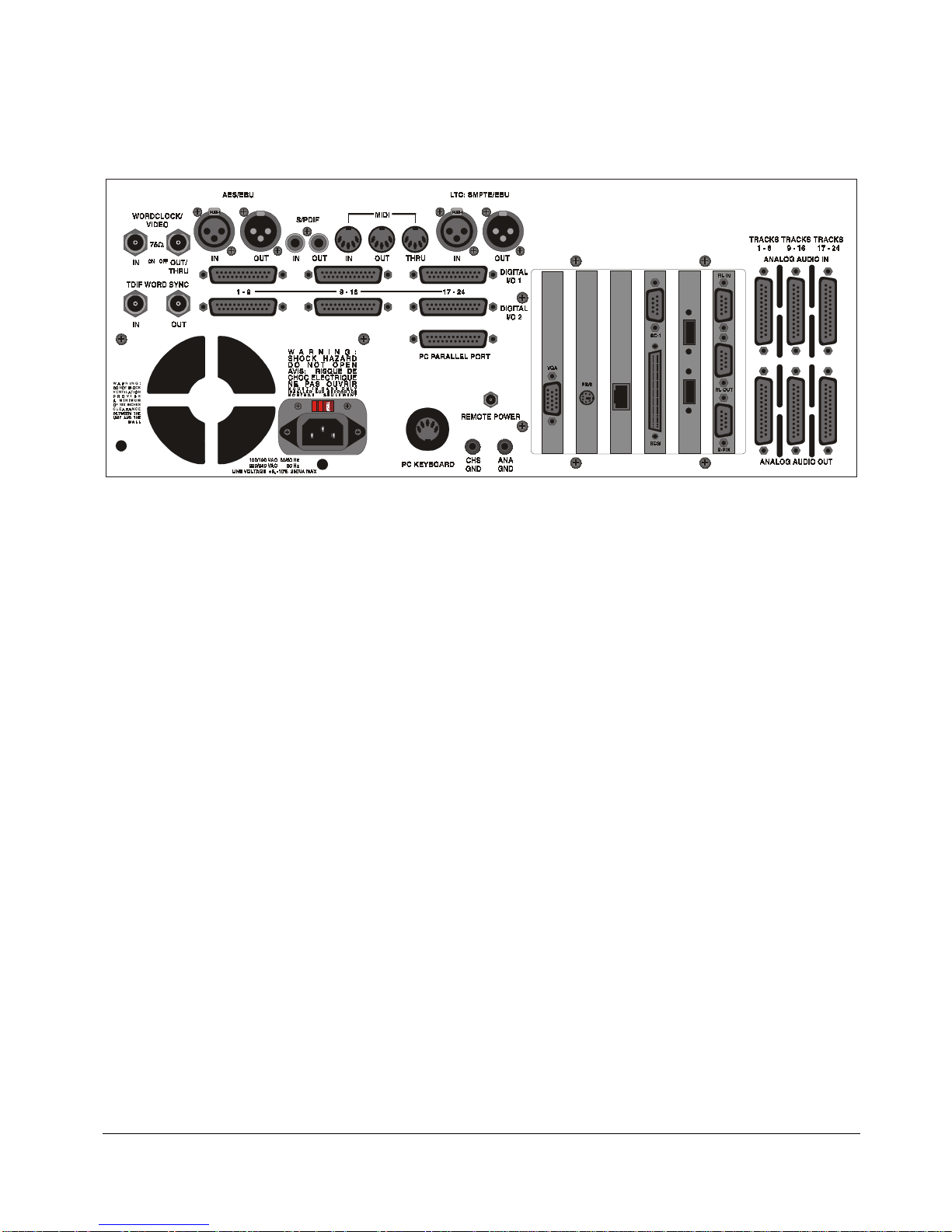
Rear Panel
The rear panel of the RADAR24 provides a wealth of professional sync and audio I/O options.
Diagram 1.1 RADAR
! REFERENCE SYNC
Reference sync signals are input via the
connector or the connectors of any installed multi-channel digital I/O boards. See S
C
ONFIGURATION
! DIGIT AL I/O
All RADAR24 units are equipped with 2 channels of digital audio I/O that can utilize either the
AES/EBU
TDIF
or
and
ADAT LIGHTPIPE
detailed information.
! POSIT ION AL SYNC
Both
O
PERATIONS
! CARD CAGE
(MIDI Time Code) and
MTC
24 Rear Panel Labeling
: S
YNC REFERENCE
interface formats. Optional multi-channel I/O cards are available for the
S/PDIF
formats. See S
: C
HASING TIME CODE
(unit shown with optional multi-channel AES/EBU, TDIF and analog I/O boards)
WORDCLOCK/VIDEO, TDIF WORD SYNC
, the 2-channel
for detailed information.
YSTEM SETUP
(SMPTE) can be used for positional synchronization. See
LTC
: C
ONFIGURATION
: D
IGITAL
for detailed information.
YSTEM SETUP
I/O F
ORMAT
AES/EBU
AES/EBU
for
:
,
The card cage contains the Ethernet, SVGA, PS/2, USB, external SCSI, 9-pin and RADARLINK
connectors. See S
! ANALOG I/O
YSTEM SETUP
The optional analog I/O boards use six female 25-pin D-Sub connectors to provide 24 channels of
balanced audio I/O. See S
: M
AKING CONNECTIONS
YSTEM SETUP
for detailed information.
: M
AKING CONNECTIONS
10
101010
for detailed information.

Section
2
System Setup
This section of the manual will help you get RADAR24 up and running in your studio as quickly as possible.
Installation
Once you have unpacked the RADAR24 please make sure to keep the box and all of the associated
packaging materials. In the unlikely event that your unit needs to be returned for service or repair, using the
original shipping box will ensure that it makes the return journey in good condition.
Make sure to consider the following before installation:
! Power supply fans and hard drives make a certain amount of noise, locating the main RADAR24
unit outside of the control room is ideal.
! AES/EBU digital lines and the Session Controller extension cable can be run for about 33 meters.
! ADAT optical and TDIF digital audio connections will limit the distance between RADAR and the
mixing console to approximately 10 meters.
! If you plan on using a monitor you will need an SVGA monitor and an SVGA extension cable if you
are putting RADAR24 in a machine room.
! Make sure that you have a reliable, properly grounded A.C. power source for the RADAR24. An
Uninterruptible Power Supply (UPS) is a fabulous idea!
Making Connections
Now that you’ve decided on where to place RADAR24 in your studio, it’s time to get hooked up. The exact
connections you’ll need will vary depending on the configuration of your unit so we’ve listed them all! Wiring
diagrams for interfacing RADAR24 are available at our website at www.recordingtheworld.com.
111111
11

A.C. Power
Connect RADAR24 to the A.C. mains using the supplied power cord. The power switch is located on the
left side of the front panel. See D
IAGRAM
1.0.
IMPORTANT NOTE: Make sure the
VOLTAGE SELECTOR
switch on the rear panel is set
to the appropriate setting before applying power to the unit. Incorrect v oltage settings ar e
!
an electrical and fire hazard and can cause ir repar able damage to y our uni t.
SCSI
Insure that the Active Terminator is attached securely to the external SCSI connector on the rear of the unit.
If additional external SCSI devices are used, remove the terminator, connect the devices and place the
terminator on the last device in the chain.
IMPORTANT NOTE: Make sure that the last device in the SCSI chain is terminated
using the supplied active terminator. Incorrect termination can cause BAD things to
!
happen to your audio.
Sync Reference
Sync reference is one of the keys to reliable digital audio interfacing and accurate positional synchronization.
WORDCLOCK/ VIDEO
Word clock and video sync can both be used as external clock sources for the RADAR24. The
VIDEO-IN
MENU / SYNC REF
connector accepts either a word clock or a video sync source. The current selection in
determines which of these formats will be used as the external sync source.
WORDCLOCK/
MAIN / SYNC
Word clock is a clock signal running at the same frequency as the sampling frequency of the digital audio
being transferred or recorded. It enables multiple digital devices to be locked together so that audio can be
reproduced, transferred and recorded without any digital noise or interfer ence.
To slave RADAR
1. Connect a word clock source to the
2. Use the
to external word clock:
MENU/PREV
, arrow keys and
WORDCLOCK/ VIDEO–IN
ENTER
key to go to the
using a 75-ohm BNC terminated cable.
MAIN / PROJ M EN U / SAM PLE R ATE
, menu and
make sure that the project sample rate matches the incoming word clock frequency.
3. Press the
keys and
SYNC/OFFSET
ENTER
key to go to the
key on the Session Controller or KC-24 or use the
4. Use the arrow keys to select
MAIN / SYNC MENU / SYNC REFERENCE
SYNC REFERENCE: WORDCLK : 48 KHZ
menu and hit the
and press the
MENU/PREV
ENTER
key.
ENTER
key, arrow
key.
Note: The word clock frequency value displayed in the Sync Reference dialog will depend on the sampling rate of the
current project NOT the rate of the incoming word clock signal.
12
121212

Video sync, also known as house sync or black burst, is used to ensure a known and accurate synchronization
relationship exists between RADAR
To slave RADAR
24 to external video sync:
1. Connect the video sync source to the
24 and all the other devices in the studio, especially video equipment.
WORDCLOCK/ VIDEO – IN
connector using a 75-ohm BNC
terminated cable. If RADAR24 is the last device in the chain make sure to terminate the video sync
connection using the 75-ohm terminator switch on the rear panel.
2. Use the
MENU/PREV
, arrow keys and
ENTER
key to go to the
MAIN / SYNC MENU / TC SETTINGS
menu and
make sure that the current project time code rate matches the incoming video sync frequency.
3. Press the
keys and
SYNC/OFFSET
ENTER
key to go to the
key on the Session Controller or KC-24 or use the
4. Use the arrow keys to select
MAIN / SYNC MENU / SYNC REFERENCE
SYNC REFERENCE: NTSC: 29.97
and press the
menu and hit the
ENTER
MENU/PREV
key.
ENTER
key, arrow
key.
Note: The video sync frequency value displayed in the Sync Reference dialog will depend on the time code rate setting of the
sync menu NOT the rate of the incoming video sync signal.
Word clock signal supplied to the
WORDCLOCK/ VIDEO-OUT/THRU
connector. In situations where RADAR24 should act as the clock master, word
clock can also be output from the
connector can be changed in the
MAIN / SYNC MENU / SYNC REF OUTPUT
WORDCLOCK/ VIDEO-IN
WORDCLOCK/ VIDEO-OUT/THRU
can be passed on to other devices using the
connector. The function of the
setting.
OUT/THRU
To switch between word clock out and thru:
1. Use the
and press the
MENU/PREV
ENTER
key, arrow keys and
key.
2. Use the right and left arrow keys to select
SMPTE / MTC
ENTER
or
OUT
key to go to the
and press the
THRU
MAIN / SYNC MENU / SYNC REF OUTPUT
ENTER
key.
Although SMPTE and MTC are primarily positional synchronization references, in some situations it is
necessary for RADAR24 to track less than ideal timing sources such as a 2” multitrack recorder or MIDI
sequencer. In this instance RADAR24 uses the incoming time code as a clock reference as well. When
referenced to SMPTE or MTC the RADAR24 will track any variations in the speed of the master flawlessly.
To slave RADAR
1. Connect the SMPTE time code source to the
unbalanced XLR terminated cable. Connect the MTC source to the
2. Use the
24 to SMPTE time code or MTC:
MENU/PREV
, arrow keys and
ENTER
LTC: SMPTE / EBU
key to go to the
connector using a balanced or
using a MIDI cable.
MIDI IN
MAIN / SYNC MENU / TC SETTINGS
menu and
make sure that the time code rate matches the incoming time code signal.
3. Press the
REFERENCE
SYNC/OFFSET
and press the
key on the Session Controller or KC-24 or go to
ENTER
key.
MAIN / SYNC MENU / SYNC
131313
13

4. Use the arrow keys to select
SYNC REFERENCE: SMPTE 30
key.
Note: The time code frequency value displayed in the Sync Reference dialog will depend on the time code rate setting of the
Sync Menu NOT the rate of the incoming time code signal.
AES 2 - CHA NNEL
The
AES/EBU
input on the rear panel is used for transferring digital audio. I t can als o be us ed to receive a clock
signal from a master clock or another digital audio device.
To slave RADAR
1. Connect the AES/EBU source to the
24 to an external AES/EBU clock source:
AES/ EBU IN
cable.
2. Press the
and
3. Use the arrow keys to select
S/PDIF 2 - CHANNEL
SYNC/OFFSET
ENTER
key to go to the
key on the Session Controller or KC-24 or use the
MAIN / SYNC MENU / SYNC REFERENCE
SYNC REFERENCE: AES 2CH SYNC
or
SYNC REFERENCE: MTC 30
and press the
ENTER
connector using an XLR terminated digital audio
menu and press the
and press the
ENTER
MENU/PREV
ENTER
key.
, arrow keys
key.
The
input on the rear panel is used for transferring digital audio. It can also be used to receive a clock
S/PDIF
signal from a master clock or another digital audio device.
To slave RADAR
1. Connect the S/PDIF source to the
2. Press the
and
3. Use the arrow keys to select
AES/EBU MULTI-CHANNEL
The
AES/EBU MULTI-CHANNEL
24 to an external S/PDIF clock source:
SYNC/OFFSET
ENTER
key to go to the
S/PDIF IN
key on the Session Controller or KC-24 or use the
MAIN / SYNC MENU / SYNC REFERENCE
SYNC REFERENCE: S/PDIF 2CH SYNC
connector using an RCA terminated digital audio cable.
menu and press the
and press the
inputs on the rear panel are used for transferring digital audio. They can also be
used to receive a clock signal from a master clock or another digital audio device.
To slave RADAR
24 to an external AES/EBU multi-channel clock source:
1. Connect the AES/EBU multi-channel source to the desired 25-pin D-sub
the appropriate digital audio cable.
2. Press the
and
SYNC/OFFSET
ENTER
key to go to the
key on the Session Controller or KC-24 or use the
MAIN / SYNC MENU / SYNC REFERENCE
menu and press the
MENU/PREV
ENTER
key.
AES/EBU
MENU/PREV
, arrow keys
ENTER
key.
connector using
, arrow keys
ENTER
key.
3. Use the arrow keys to select
SYNC REFERENCE: AES MULTI CH
14
141414
and press the
ENTER
key.

Note: If you do not have AES/EBU cards installed then you will get an alert dialog stating:
ADAT
The
INSTALLED
optical inputs on the rear panel can be used for transferring audio from other devices to the
ADAT
.
NO AES MULTI-CH CARDS
RADAR24 and they can be used as a clock source.
To slave RADAR
1. Connect the ADAT source to the desired optical
2. Press the
and
3. Use the arrow keys to select
Note: If you do not have ADAT cards installed then you will get an alert dialog stating:
TDIF L/R IN
The
inputs on the rear panel can be used for transferring audio from other devices to the RADAR24
TDIF
24 to an external ADAT clock source:
SYNC/OFFSET
ENTER
key to go to the
ADAT IN
key on the Session Controller or KC-24 or use the
MAIN / SYNC MENU / SYNC REFERENCE
SYNC REFERENCE: ADAT
connector using a lightpipe cable.
menu and press the
and press the
ENTER
key.
NO ADAT CARDS INSTALLED
MENU/PREV
ENTER
, arrow keys
key.
.
and they can be used as a clock source. This clock is embedded in the TDIF audio signal and is a different
clock than TDIF Word Sync.
To slave RADAR
1. Connect the TDIF source to the desired 25-pin D-sub
24 to an external TDIF L/R clock source:
connector using the appropriate digital
TDIF
audio cable.
2. Press the
and
3. Use the arrow keys to select
SYNC/OFFSET
ENTER
key to go to the
key on the Session Controller or KC-24 or use the
MAIN / SYNC MENU / SYNC REFERENCE
SYNC REFERENCE: TDIF L/R IN
and press the
menu and press the
Note: If you do not have TDIF cards installed then you will get an alert dialog stating:
use purpose built TDIF cables, pin-to-pin cables will
TDIF WORD SYNC
The
TDIF WORD SYNC
input on the rear panel is used to provide a more reliable clock source when transferring
ENTER
NO TDIF CARDS INSTALLED
not
work!
MENU/PREV
ENTER
key.
, arrow keys
key.
. You MUST
digital audio between devices using TDIF. This clock is similar to a word clock but differs in its phase
relationship to the data signal. It should not be confused with the embedded L/R data clock in the TDIF
digital audio signal.
To slave RADAR
1. Connect the TDIF word sync source to the
24 to external TDIF Word Sync:
TDIF WORD SYNC
connector using a 75-ohm, BNC
terminated cable.
151515
15

2. Press the
and
3. Use the arrow keys to select
SYNC/OFFSET
ENTER
key to go to the
key on the Session Controller or KC-24 or use the
MAIN / SYNC MENU / SYNC REFERENCE
SYNC REFERENCE: TDIF WORD SYNC
menu and press the
and press the
Note: If you do not have TDIF cards installed then you will get an alert dialog stating:
MENU/PREV
ENTER
ENTER
key.
NO TDIF CARDS INSTALLED
, arrow keys
key.
.
Audio Cabling
Please always use the highest quality cables with your RADAR24. The cables described below are available
on our website and in most music and pro audio stores around the world. Additionally, wiring diagrams are
available for the do-it-yourselfer at www.recordingtheworld.com .
ANALOG
Analog cables for the RADAR24 share the same wiring scheme as analog cables for the T ASCAM DA-88
and other popular modular digital multitrack recorders. The RADAR24 end of each analog cable is a 25-pin
D-sub connector that carries eight independent, balanced, line level audio signals. Altogether there ar e six
cables required, three for input and three for output, for 24 channels of ultra-high quality analog audio I/O.
The other end of each analog cable typically breaks out to individual XLR or TRS connectors for connection
to a console’s Tape Inputs and Buss Outputs. Another often-used approach is to wire directly into a patch
bay for the ultimate in routing flexibility.
DIGITAL
There are several digital I/O options available for RADAR24 and each one has different cabling
requirements.
AES/EBU 2-CHANNEL
The cable required for the AES/EBU 2-channel interface is an XLR terminated 110-ohm digital audio cable.
One cable is required for 2 channels of input and an additional cable is required for 2 channels of output.
S/PDIF 2-CHANNEL
The cable required for the S/PDIF 2-channel interface is an RCA terminated 110-ohm digital audio cable.
One cable is required for 2 channels of input and an additional cable is required for 2 channels of output.
AES MULTI-CHANNEL
The RADAR24 AES/EBU multi-channel I/O uses the same wiring scheme as the TASCAM DA-88 and
other popular modular digital multitrack recorders. Both ends of each AES/EBU multi-channel cable are
terminated with 25-pin D-sub connectors. Each cable carries eight channels of input and eight channels of
output. Altogether there are three cables required for 24 channels of digital I /O. Another available cabling
option breaks out to 4 male (8 outputs) and 4 female (8 inputs) XLR connectors. This type of cable is
necessary for connecting to some types of mixers and certain digital audio workstations.
161616
16

TDIF
Audio: The RADAR24 TDIF I/O uses the same wiring scheme as the TASCAM DA-88 and other popular
modular digital multitrack recorders. Both ends of each TDI F cable are terminated with a 25-pin D- sub
connector. Each cable carries eight channels of input and eight channels of output. Altogether there are thr ee
cables required for 24 channels of digital I/O.
Sync: In addition to the TDIF audio cabling requirements there is a TDIF word sync connection that may be
necessary for interfacing under certain circumstances . This connection can be made us ing a 75-ohm, BNC
terminated cable.
ADAT
Lightpipe connections can be made with any optical fiber that is approved for use with the Alesis ADAT
system. Each fiber carries eight channels of digital audio. Thr ee input and three output Lightpipe fibers
provide 24 channels of ADAT
I/O.
Time Code
You can use either SMPTE or MTC (MIDI Time Code) formats for positional synchronization reference
with RADAR24. All industry standard frame counts and frame rates are supported.
SMPTE
SMPTE, also known as LTC or Longitudinal Time Code, is connected using the XLR
connectors on the rear panel. The LTC inputs and outputs can be either balanced or unbalanced. The
OUT
LTC: SMPTE/EBU IN
and
LTC input has a sensitivity ranging between 100mV and 20V. The output is 1V peak to peak. This will
produce a –7 VU meter reading on a +4 device like a professional analog tape machine.
Note: When using unbalanced lines, pin 3 should be connected to the shield.
MTC
MIDI time code is input and output using the
MIDI IN
and
MIDI OUT
connectors on the rear panel of the
RADAR24.
To switch between SMPTE and MTC time code formats:
1. Press
SHIFT+CHASE(TC PREF)
arrow keys and
ENTER
on the Session Controller or the KC-24 or use the
key to go to the
MAIN / SYNC MENU / TC SETTINGS
2. Use the right and left arrow keys to select
SMPTE
or
MTC
and press the
menu and press the
ENTER
key.
MENU/PREV
ENTER
key.
,
171717
17

Session Controller / KC-24
SESSION CONTROLLER
There are two connections required on the back panel of RADAR24 to attach the Session Controller remote
cable.
Power: Insert the barrel plug of the Session Controller cable into the power receptacle labeled
REMOTE POWER
on the rear of the unit.
Data: Attach the 9-pin D-sub connector of the Session Controller cable to the 9-pin receptacle located
directly above the SCSI terminator in the card cage section of the back panel.
KC –24 KEYBOARD
The KC-24 attaches to the RADAR24 using the keyboard’s connector plug and a 5-pin DIN adaptor. The
keyboard receptacle, located just to the right of the A.C. power connector, is inset in a round hole labeled
KEYBOARD
.
PC
Monitor (optional)
Any standard SVGA monitor (800x600 resolution) can be attached directly to the RADAR24. The monitor
connection is a 15-pin D-sub connector located on the far left of the card cage section on the back panel.
RADARLINK
RADARLINK allows multiple RADAR units to be synchronized so that they can be operated together as a
single machine. The 9-pin D-sub
RLINK IN
and
RLINK OUT
connectors used for RADARLINK are located on
the far right hand side of the card cage section on the rear of the unit. Connection between two units can be
made using the cable supplied with a multiple unit purchase or by using any 9-pin D-sub cable that is wired
pin-to-pin. These can be purchased from iZ Technology or from an electronics or computer retailer in your
area.
Note: Make sure that the cable is wired pin-to-pin! Some 9-pin cables have modified pin-outs and will not work for this
Ethernet
RADAR24 ships with a 10/100 Base T Ethernet card that can be used for backing up, tr ansferring and
exporting files. You can connect to an NT server or connect to a PC or a Mac in a peer-to-peer configuration.
The Ethernet card is located in the card cage just to the left of the Adr enaline card, which has the active
SCSI terminator on it.
Machine Control
RADAR24 supports two formats of machine control, Sony 9-pin (RS-422) and MMC or MIDI Machine
Control. These control protocols allow RADAR24 to be controlled from other equipment like video decks
application.
18
181818

or mixers. Sony 9-pin uses a 9-pin D-sub terminated cable to transmit transport, record status and other
control information. MMC uses MIDI to transmit similar types of information.
To switch between 9-pin and MMC machine control formats:
1. Use the
press the
MENU/PREV
ENTER
key.
, arrow keys and
2. Use the up and down arrow keys till
ENTER
SELECT TYPE
3. Use the right and left arrow keys to select
key to go to the
is displayed and press the
9-PIN
or
and press the
MMC
MAIN / SYNC MENU / MACHINE CONTROL
ENTER
key.
ENTER
key.
and
To enable or disable machine control:
1. Press
2. Use the up and down arrow keys till
SHIFT+RLINK(MCH CTL)
ENTER
key to go to the
on the Session Controller or use the
MAIN / SYNC MENU / MACHINE CONTROL
ENABLE/D ISABLE
3. If machine control is disabled pressing the
pressing the
ENTER
key will disable it.
and press the
is displayed.
ENTER
key will enable it. If machine control is enabled
MENU/PREV
ENTER
key.
, arrow keys and
Configuration
Now that you have your RADAR24 hooked up and ready to go, we can help you make sure that the system
settings are configured correctly for your situation.
Operating Level
You can match the input and output levels of RADAR24 with the input and output levels of other pieces of
equipment in your studio. Although the inputs and outputs can be adjusted independently, all inputs share the
same operating level. The same holds true for all of the outputs.
Because a zero meter reading on a digital recorder represents the absolute maximum level that can be
recorded, a much lower nominal signal level should be specified. With analog VU meters, 0 VU represented
this nominal signal level and above that there was “headroom”, which allowed for dynamic surges and
transients. With today’s digital recorders a 0 VU signal level usually corresponds to a digital meter reading
somewhere between –14 and –20. This is where the operating level of the RADAR24 comes in. There are
four different settings for input level and four different settings for output level. They are:
+24 dBu – results in a digital meter reading of –20 when a 0 VU tone is applied
+22 dBu – results in a digital meter reading of –18 when a 0 VU tone is applied
+20 dBu – results in a digital meter reading of –16 when a 0 VU tone is applied
+18 dBu – results in a digital meter reading of –14 when a 0 VU tone is applied
191919
19

To set the input and output operating levels:
1. Use the
press the
MENU/PREV
ENTER
key.
, arrow keys and
2. Use the right and left arrow keys to select either
ENTER
key to go to the
AUDIO IN or AUDIO OUT
3. Use the up and down arrow keys to select the desired operating level and press the
MAIN / SYS MENU / AUDIO I/O LEVELS
.
ENTER
key.
and
Sync Reference
The sync reference setting will vary widely depending on the application and the configuration of your system.
It will also depend on whether or not RADAR24 is the master or slave in your particular setup. You can gain
instant access to the sync settings using the
To make RADAR
24 the digital audio sync master using the word clock output:
1. Ensure that a word clock cable is connected to the
2. Press the
ENTER
SYNC
key on the Session Controller or KC-24 or use the
key to go to the
MAIN / SYNC MENU / SYNC REFERENCE
3. Use the arrow keys to select
4. Use the
and press the
MENU/PREV
ENTER
key, arrow keys and
key.
SYNC
key on the Session Controller and the KC-24.
WORDCLOCK/ VIDEO – OUT/THRU
SYNC REFERENCE: INTERNAL
ENTER
key to go to the
MENU/PREV
menu and press the
and press the
ENTER
MAIN / SYNC MENU / SYNC REF OUTPUT
connector.
key, arrow keys and
ENTER
key.
key.
5. Use the right and left arrow keys to select
and press the
OUT
ENTER
key.
For digital audio transfers to a digital mixer or other digital audio device a reliable clock source is mandatory.
Without proper data synchronization digital audio will exhibit pops, clicks and other unpleasant artifacts. In a
film or video post environment video sync is usually distributed to all the video, audio and clock devices in the
studio to ensure that every thing is synchronous with the video signal right down to the sample level. For
synchronizing with analog tape decks that exhibit fluctuations in transport speed, RADAR24 can even
reference to the incoming SMPTE signal. In this configuration RADAR24 will fluctuate right along with the
analog master ensuring perfect synchronization at all times!
To slave RADAR
1. Ensure that a word clock source is connected to the
your projects sample rate in the
24 to external word clock:
MAIN / PROJ ME NU / SAMPLE RATE
WORDCLOCK/ VIDEO – IN
dialog matches the incoming word
connector. Make sure that
clock frequency.
2. Press the
ENTER
SYNC
key on the Session Controller or KC-24 or use the
key to go to the
MAIN / SYNC MENU / SYNC REFERENCE
3. Use the arrow keys to select
menu and press the
SYNC REFERENCE: WORDCLCK : 48 KHZ
MENU/PREV
and press the
key, arrow keys and
ENTER
key.
ENTER
key.
202020
20

If you will be passing word clock through the RADAR24 make sure that the function of the
connector is set to
THRU
in the
MAIN / SYNC MENU / SYNC REF OUTPUT
dialog.
Note: The word clock frequency value displayed in the Sync Reference dialog will depend on the sampling rate of the
current project NOT the rate of the incoming word clock signal.
To slave RADAR
1. Ensure that a video sync source is connected to the
your projects time code rate in the
24 to external video sync:
MAIN / SYNC MENU / TC SETTINGS
WORDCLOCK/ VIDEO – I N
menu matches the incoming video
connector. Make sure that
sync frequency.
2. Press the
ENTER
SYNC
key on the Session Controller or KC-24 or use the
key to go to the
MAIN / SYNC MENU / SYNC REFERENCE
3. Use the arrow keys to select
SYNC REFERENCE: NTSC: 29.97
menu and press the
and press the
MENU/PREV
ENTER
ENTER
key.
key, arrow keys and
key.
Note: The video sync frequency value displayed in the Sync Reference dialog will depend on the time code rate setting of the
sync menu NOT the rate of the incoming video sync signal.
To slave RADAR
1. Ensure that a valid SMPTE time code source is connected to the
balanced or unbalanced XLR terminated cable. Connect an MTC source to the
24 to SMPTE time code or MTC:
LTC: SMPTE / EBU
MIDI IN
connector using a
using a MIDI
cable.
OUT/THRU
2. Use the
MENU/PREV
, arrow keys and
make sure that the time code rate matches the incoming time code signal.
3. Press the
and press the
4. Use the arrow keys to select
SYNC
key on the Session Controller or KC-24 or go to
ENTER
key.
SYNC REFERENCE: SMPTE 30
key.
Note: The time code frequency value displayed in the Sync Reference dialog will depend on the time code rate setting of the
Sync Menu NOT the rate of the incoming time code signal.
To slave RADAR
24 to an external AES/EBU clock source:
1. Connect an AES/EBU source to the
cable.
2. Press the
ENTER
3. Use the arrow keys to select
SYNC
key on the Session Controller or KC-24 or use the
key to go to the
MAIN / SYNC MENU / SYNC REFERENCE
SYNC REFERENCE: AES 2CH SYNC
ENTER
key to go to the
AES/ EBU IN
MAIN / SYNC MENU / TC SETTINGS
MAIN / SYNC MENU / SYNC REFE RENCE
or
SYNC REFERENCE: MTC 30
and press the
menu and
ENTER
connector using an XLR terminated digital audio
MENU/PREV
menu and press the
and press the
ENTER
, arrow keys and
ENTER
key.
key.
212121
21

To slave RADAR
1. Connect the S/PDIF source to the
2. Press the
ENTER
3. Use the arrow keys to select
To slave RADAR
24 to an external S/PDIF clock source:
S/PDIF IN
SYNC
key on the Session Controller or KC-24 or use the
key to go to the
24 to an external AES/EBU multi-channel clock source:
MAIN / SYNC MENU / SYNC REFERENCE
SYNC REFERENCE: S/PDIF 2CH SYNC
connector using an RCA terminated digital audio cable.
menu and press the
and press the
1. Connect the AES/EBU multi-channel source to the desired 25-pin D-sub
the appropriate digital audio cable.
2. Press the
ENTER
3. Use the arrow keys to select
SYNC
key on the Session Controller or KC-24 or use the
key to go to the
MAIN / SYNC MENU / SYNC REFERENCE
SYNC REFERENCE: AES MULTI-CH
menu and press the
and press the
Note: If you do not have AES/EBU cards installed then you will get an alert dialog stating:
To slave RADAR
INSTALLED
24 to an external ADAT clock source:
.
MENU/PREV
ENTER
AES/EBU IN
MENU/PREV
ENTER
NO AES MULTI-CH CARDS
, arrow keys and
ENTER
key.
key.
connector using
, arrow keys and
ENTER
key.
key.
1. Connect the ADAT source to the desired optical
2. Press the
ENTER
3. Use the arrow keys to select
SYNC
key on the Session Controller or KC-24 or use the
key to go to the
MAIN / SYNC MENU / SYNC REFERENCE
SYNC REFERENCE: ADAT
ADAT IN
connector using a light pipe cable.
menu and press the
and press the
Note: If you do not have ADAT cards installed then you will get an alert dialog stating:
To slave RADAR
1. Connect the TDIF source to the desired 25-pin D-sub
24 to an external TDIF L/R clock source:
TDIF
audio cable.
2. Press the
ENTER
3. Use the arrow keys to select
SYNC
key on the Session Controller or KC-24 or use the
key to go to the
MAIN / SYNC MENU / SYNC REFERENCE
SYNC REFERENCE: TDIF L/R IN
and press the
menu and press the
Note: If you do not have TDIF cards installed you will get an alert dialog stating:
purpose built TDIF cables pin-to-pin cables will not work!
ENTER
MENU/PREV
key.
NO ADAT CARDS INSTALLED
, arrow keys and
ENTER
key.
.
connector using the appropriate digital
MENU/PREV
ENTER
key.
NO TDIF CARDS INSTALLED
, arrow keys and
ENTER
key.
. You MUST use
222222
22

To slave RADAR
1. Connect the TDIF word sync source to the
24 to external TDIF Word Sync:
TDIF WORD SYNC IN
connector using a 75-ohm, BNC
terminated cable.
2. Press the
ENTER
3. Use the arrow keys to select
SYNC
key on the Session Controller or KC-24 or use the
key to go to the
MAIN / SYNC MENU / SYNC REFERENCE
SYNC REFERENCE: TDIF WORD SYNC
menu and press the
and press the
Note: If you do not have TDIF cards installed then you will get an alert dialog stating:
MENU/PREV
ENTER
NO TDIF CARDS INSTALLED
, arrow keys and
ENTER
key.
key.
.
Digital I/O Format
The digital I/O formats available for selection will depend on the type and number of digital interface options
installed in your RADAR24. All units ship with built in AES/EBU and S/PDIF 2-channel interfaces. The
24 channel digital I/O options available include: AES/EBU, ADAT and TDIF.
It is important to note that once a digital format is selected an appropriate clock source must be selected as
well. Many times they are one and the same thing, but not always. For instance, an AES transfer may be
required but the sync refere nce for all digital de vices in the studio may be a word c lock gene rator refere nced
to video sync. You get the picture.
Using the
MAIN / DIGIO MENU/ DIGITAL I/O ROUTING/ MULTI CH IN TRKS
menu dialog you can choose
ALL
or
SELECT
which tracks will use the selected digital I/O. The tracks that are not selected will use the analog I/O.
Note: When a digital input format is specified one track must always be set to digital. To return all 24 tracks to analog input
select NONE. See below.
NONE
This selection disengages the digital I/O and returns all 24 inputs to analog input.
AES/EBU 2-CHANNEL
This 2-channel format uses a single cable for 2 channels of digital audio transmission. It is unidirectional so
one cable is required for input and one for output.
S/PDIF 2-CHANNEL
S/PDIF also uses a single cable for 2 channels of digital audio transmission. It is unidirectional as well so one
cable is required for input and one for output. It is essentially a consumer version of AES/EBU.
AES MULTI-CHANNEL
With multi-channel AES/EBU each cable carries eight channels. This for mat is bi-dir ectional so only three
cables are required for 24 channels of digital audio I/O.
232323
23

TDIF
This format also uses three bi-d irectional cables carr ying eight channels of audio each, for a total of 24
channels of digital I/O.
ADAT
Lightpipe optical fibers carry eight channels of digital audio. This format is unidirectional so you’ll need three
input and three output Lightpipe “cables” for 24 channels of ADAT
I/O.
To select a digital I/O format:
1. Make sure that all your cabling is connected properly.
2. Press the
to go to the
DIG IN
key on the Session Controller or use the
MAIN / DIGIO MENU / DIG IN FORMAT
menu and press the
3. Use the up and down arrow keys to select the digital format of your choice and pres s the
Note: If you do not have a particular card installed you will get an alert dialog stating:
MENU/PREV
ENTER
key.
NO ________ CARDS INSTALLED
, arrow keys and
ENTER
ENTER
key
key.
.
To select tracks for digital input:
1. Press
SHIFT+DIG IN(ROUTE)
ENTER
key to go to the
key on the Session Controller or use the
MAIN / DIGIO MENU/ DIGITAL I/O ROUTING
2. Use the up and down arrow keys to select
3. Use the right and left arrow keys to select
MULTI-CH IN TRKS
ALL
or
SELECT
and press the
menu and press the
and press the
MENU/PREV
ENTER
ENTER
ENTER
key.
key.
, arrow keys and
key.
To select source and destination tracks for the digital 2-channel I/O:
1. Press
2. Use the up and down arrow keys to select
SHIFT+DIG IN(ROUTE)
ENTER
keys to go to the
key on the Session Controller or use the
MAIN / DIGIO MENU/ DIGITAL I/O ROUTING
2 CH I/O ROUTING
3. Use the right, left, up and down arrow keys to select
track numbers in each one and press the
ENTER
key.
menu and press the
and press the
IN L, IN R, OUT L
or
MENU/PREV,
ENTER
key.
ENTER
key.
fields, enter the desired
OUT R
arrow and
Time Code
There are two distinct protocols of positional time code that are supported by RADAR24: SMPTE/EBU
and MIDI time code or MTC. Both support all industry standard frame counts and rates. While chasing time
code it is normal practice to reference RADAR24’s clock either directly to the incoming time code signal or
to an external word clock or video sync source. These clock s ources ar e set s eparately in the
SYNC REFERENCE
menu.
MAIN / SYNC MENU /
242424
24

When slaved to an analog tape machine it is critical that RADAR24 follow any deviation in speed introduced
by the tape transport. In this scenario the incoming time code is smoothed and averaged to create a stable
reference signal for the internal clock of the RADAR24. Because the internal clock will constantly match the
incoming clock source in this configuration, RADAR
24 will follow the master exactly, even if you use vari-
speed!
In other applications where all the devices in a system are referenced to video sync (AKA black burst or
house sync), RADAR24 can be referenced to video sync directly or to a word clock generator that is in turn
referenced to the video sync source. A system wide sync source is critical for video and film production and
post-production work because it creates a known relationship between the positional time code and the
timing information present in the video signal.
Note: For more information on sync reference, refer to C
ONFIGURATION
: S
YNC REFERENCE
earlier in this manual.
To select time code format and frame count/rate:
1. Press
SHIFT+CHASE(TC PREF)
ENTER
and
key to go to the
key on the Session Controller or use the
MAINSYNC MENU/ TC SETTINGS/ TC FORMAT
2. Use the right and left arrow keys to select
3. Use the right and left arrow keys to select
or
SMPTE
24, 25, 29.97ND, 29.97DF, 30ND,
and press the
MTC
menu and press the
ENTER
or
MENU/PREV
key.
and press the
30DF
, arrow keys
ENTER
key.
ENTER
key.
Networking
The RADAR24 ships with a 10/100 Base T Ethernet card. With the appropriate hardware and properly
configured software RADAR24 can backup, restore, export and import files using an Ethernet connection
to a CIFS (Windows, Unix, OS X with CIFS server) server or by using a specially wired crossover cable for a
connection with a personal computer.
Networking is a very BIG topic and is far beyond the scope of this manual. Our goal is to get your
RADAR24 configured so that it can be integrated into an existing network or connected to a personal
computer using peer-to-peer. For instructions on how to transfer files see O
DISCLAIMER: iZ Technology cannot offer advic e on networ king and security issues that
PERATIONS
: F
ILE TRANSFER
.
do not directly pertain to the RADAR24 system. For further assistance please consult a
networking professional or make use of the extensi v e resource mater ials av ailabl e on
!
the Internet.
ENTERING THE SERVER OR PEER-TO-PEER NETWORK INFORMATION
Before RADAR24 can connect via Ethernet it must be configured with information about the system it will
be connecting to. For instructions on how to transfer files please refer to O
To enter CIFS Server or Peer-To-Peer connection information:
1. Use the
SERVER PREFS
MENU/PREV
and press the
, arrow keys and
ENTER
key.
ENTER
key to go to
25
252525
PERATIONS
MAIN / PREFERENCES MENU / NETWORK SETUP /
: F
ILE TRANSFER
.

2. Use the up and down arrows to locate the
CIFS SERVER IP
menu item and press the
ENTER
key.
3. Use the numeric keypad and right and left arrow keys to enter the IP address of the computer you
wish to export to and press the
4. Enter the host name of the computer you want to export to in the
5. Enter the name of the shared folder you’ve created on the computer in the
6. Enter the name of the workgroup your computer belongs to in the
PEER-TO-PEER
ENTER
key.
SERVER NA ME
CLIENT WORKGROUP
dialog.
SERVER SHA RE
dialog.
dialog.
RADAR24 can connect to a PC or Macintosh via Ethernet with the appropriate cabling and software. For
instructions on how to transfer files see O
PERATIONS
: F
ILE TRANSFER
To setup for a peer-to-peer connection with a P.C. running Windows:
1. Use the
INTERFACE PREFS
MENU/PREV
and press the
, arrow keys and
ENTER
ENTER
key.
key to go to
2. Enter a unique name for your RADAR24 in the
HOST NAME
MAIN / PREFERENCES MENU / NETWORK SETUP /
field.
3. Enable or disable
DHCP
. If
is enabled then the following six steps will not apply and you may
DHCP
proceed to step 10.
4. Use the numeric keypad and the left and right arrow keys to enter a unique IP address and press the
ENTER
key.
The Internet Assigned Numbers Authority has set certain IP address ranges for use in private
networking applications:
! Class A 10.0.0.0—10.255.255.255
! Class B 172.16.0.0—172.31.255.255
! Class C 192.168.0.0—192.168.255.255
In a self-contained peer-to-peer network that never sees the outside world you may use any IP
address range you choose. However, care should be taken when assigning IP addresses to avoid
potential security risks and IP address conflicts. For further information you can visit the Internet
Assigned Numbers Authority site at http://www.iana.org.
5. Unless your network requires a
SUBNET MASK
enter a subnet mask value of 255.255.255.0 (default value) and press the
, use the numeric keypad and right and left arrow keys to
ENTER
key. The
SUBNET MASK
value must match the subnet mask value of the connected personal computer.
6. The
GATEWAY
entry does not apply for this application, you may leave entry blank.
262626
26

7. The
8. The
9. The
10. Although the
DNS DOMAIN NAME
PRIMARY DNS
SECONDARY DNS
FTP SERVING
you are not using this feature. The following menu items will only appear if
11. The
12. The
FTP LOGIN NAME
FTP PASSWORD
entry does not apply for this application, you may leave entry blank.
setting does not apply for this application, you may leave entry blank.
setting does not apply for this application, you may leave entry blank.
setting does not apply for this application, make sure it is disabled when
FTP SERVING
entry does not apply for this application, you may leave entry blank.
entry does not apply for this application, you may leave entry blank.
is enabled.
IMPORTANT NOTE: If FTP serving is left enabled and your RADAR24 is connected to
another computer or network it is possible for someone to gai n unauthoriz ed access to
!
your machine. This would give an intruder the ability to modify or delete files on your
RADAR24.
To setup a peer-to-peer connection with a Macintoshcomputer:
The Macintosh requires software that allows it to be a CIFS server. It is also poss ible to use FT P to transfer
files from RADAR24 to a Mac using an FTP Client; see C
ONFIGURATION
: N
ETWORKING
: FTP for more
information. All of the RADAR24 settings will be identical to the peer-to-peer setup for the PC. For
instructions on how to transfer files please refer to O
PERATIONS
: F
ILE TRANSFER
WINDOWS SERVER
Using the TCP/IP protocol RADAR24 can be integrated into a Windows
networking environment.
Note: In a networked environment you must be very careful about the network settings you choose. There is a real risk of causing
network conflicts and/or creating security issues. Please consult y our networ k administrato r fo r the appr opriate networ k settings for
your RADAR24.
To setup RADAR
1. Use the
INTERFACE PREFS
2. Enter a unique
3. Enable or disable
24 on a network:
MENU/PREV
, arrow keys and
and press the
HOST NAME
DHCP
ENTER
ENTER
key.
for your RADAR24.
. If
is enabled then the following six steps will not apply and you may
DHCP
key to go to
MAIN / PREFERENCES MENU / NETWORK SETUP/
proceed to step 10.
4. Use the numeric keypad and right and left arrow keys to enter an IP addr ess and pr ess the
5. Use the numeric keypad and right and left arrow keys to enter a
ENTER
key.
SUBNET MASK
value and press the
ENTER
key.
6. The
GATEWAY
entry does not apply for this application, you may leave entry blank.
272727
27

7. Enter the
8. Enter the
9. The
SECONDARY DNS
10. Although the
you are not using this feature. The following menu items will only appear if
11. The
12. The
FTP
FTP LOGIN NAME
FTP PASSWORD
DNS DOMAIN NAME
PRIMARY DNS
address only applies if there is a secondary s erver on the network.
FTP SERVING
entry does not apply for this application, you may leave entry blank.
entry does not apply for this application, you may leave entry blank.
for your network.
address for the server.
setting does not apply for this application, make sure it is disabled when
FTP SERVING
is enabled.
RADAR24 has a built in FTP or File Transfer Protocol server. This allows you to gain access to the internal
IDE drive of the RADAR24 using a network connection. Any files on the removable SCSI recording drive
must first be exported temporarily to the IDE drive. Once on the IDE drive, any FTP client can be used to
download the files into a Mac or PC for further editing. For instructions on how to transfer files please refer
to O
PERATIONS
To setup FTP access for RADAR
: F
ILE TRANSFER
24:
1. Use the
INTERFACE PREFS
2. Enter a unique
MENU/PREV
and press the
HOST NAME
3. Enable or disable
, arrow keys and
ENTER
for your RADAR24.
DHCP
. If
is enabled then the following six steps will not apply and you may
DHCP
ENTER
key.
key to go to
MAIN / PREFERENCES MENU / NETWORK SETUP/
proceed to step 10.
4. Use the numeric keypad and right and left arrow keys to enter an IP addr ess and pr ess the
ENTER
key.
5. Use the numeric keypad and right and left arrow keys to enter a subnet mask value of 255.255.255.0
(default value) and press the
ENTER
key. The
SUBNET MASK
value must match the subnet mask value of
the connected personal computer.
6. A
GATEWAY
entry is only required if you are connected to a WAN (wide area network) such as the
Internet. Use the numeric keypad and right and left arrow keys to enter a gateway IP address and
press the
7. The
QWERTY keys enter a domain name and press the
8. The
ENTER
key.
DNS DOMAIN NAME
PRIMARY DNS
address for the server is only required f or connecting to a client-ser ver network.
is only required if you are connected to a client-server network. Using the
ENTER
key.
9. The
SECONDARY DNS
address only applies if there is a secondary server on a client-server network.
10. Use the right and left arrow keys to select
ENABLED
28
282828
in the
FTP SERVING
dialog and press the
ENTER
key.

11. The
FTP LOGIN NAME
enter a login name and press the
is required for accessing the RADAR24 via FTP. Using the QWERTY keys
ENTER
key. This login name will be required by the FTP client
application on the personal computer.
12. The
FTP PASSWORD
keyboard to enter a password and press the
is also required for accessing the RADAR24 via FTP. Use the QWERTY
ENTER
key. This password will be required when
connecting using an FTP client application on the personal computer.
Preferences
Every time a new project is created, there a number of settings that are required by the RADAR
24: sample
rate, bit depth, TC format etc. In order to save you time and effort, RADAR24 assigns these values
automatically using the current values selected in the
PREFERENCES MENU
.
To set the preferences for newly created projects:
1. Use the
ENTER
key.
MENU/PREV
, arrow keys and
ENTER
key to go to the
MAIN / PREFERENCES MENU
and press the
2. Review and modify the settings in the sub-menus to your specifications.
Software
Although your RADAR24 is shipped to you with the latest version of RADAR software, you will want to
make sure that you keep it up to date by downloading new versions of the software as they become available.
We are constantly working to add new features and to improve the performance and reliability of our product
so it is certainly worth the effort. Software updates and downloading instructions are available from our
website at www.recordingtheworld.com.
To install a new version of RADAR software:
1. Use the
press the
MENU/PREV
ENTER
key.
, arrow keys and
ENTER
2. Use the up and down arrows to select
ENTER
key.
key to go to the
at the
YES
SYSTEM UPGRADE PROCEED?
MAIN / SYSTEM MENU / UPGRADE SYSTEM
prompt and press the
and
All projects will be converted to a special version-independent state and the disk(s) will be
unmounted. If you have other disks that you wish to convert to a version independent format you
can insert them at this time. To convert them simply mount them using the
MOUNT
key or
MOUNT
menu item and repeat steps 1 through 3.
3. Insert the first install floppy disk containing the new version of software and reboot the machine
using the power switch.
4. Insert additional disks as prompted to complete the install.
292929
29

Once the software is successfully installed RADAR24 will automatically run. Any attached SCSI
drives will be mounted and any projects on the disk will be converted from the version independent
state to the new project format.
Note: Upgrade System should also be used when disks will be used on other RADAR
versions of software or when using a RADAR
24 disk in a RADAR I or II.
24 units running different
303030
30

Section
3
Operations
This section of the manual is dedicated to providing you with a quick reference that can answer questions you
might have about displays, key functionality, menus, entering values, project management, backup and restore.
Overview
RADAR24 is designed to be a robust and dependable replacement for analog multitrack tape machines or
modular digital multitrack recorders. It is also designed to be easy to use. The remote interface is intuitive to
anyone familiar with the operation of a tape recorder. Just arm a track and drop into record!
All aspects of RADAR24 performance are designed to meet and exceed the performance requirements of a
professional tape recorder. You will always be able to record, punch in and out, jog/shuttle and even varispeed just like you would on a tape machine. In the section that follows, you will find all the information you
need to become a certified RADAR24 expert.
Work Flow
Without getting into details yet, the average RADAR24 session follows a pattern similar to the following:
1. Create a new project or go to an existing one.
2. Locate your starting point.
3. Arm tracks and record audio.
4. Re-locate, arm tracks and overdub more audio.
5. Edit audio.
6. Play back the audio for mix down.
7. Archive audio to backup media.
8. Shut down RADAR24 and go home (optional).
313131
31

Display Overview
While most RADAR24 users connect an SVGA monitor and make use of the RADAR View display, it is
important to note that you don’t need to use a monitor if you purchased the optional Session Controller. This
makes RADAR24 exceptionally portable and ideally suited for remote applications. It also lends itself to
more artist focused tracking sessions. Because there’s no need to stare at a glaring computer monitor in the
control room, you can actually focus on the performance! Having said that; RADAR View is very cool.
Both the Session Controller and the RADAR View display the current position within your project. This
information can be viewed in several different ways:
FEET/FRAMES
This is used for some film applications.
BARS/BEATS
The RADAR24 tempo setting is used to calculate and display positions based on musical notation. This can
be handy when working with a locked MIDI sequencer.
SMPTE
This is the default HH:MM:SS:FF plus sub-frames display.
INT/EXT SMPTE
While in
, the Session Controller will display your projects current time above the master machines
CHASE
current time code position. The RADAR View display shows only the master machines time code pos ition in
this mode.
Note: RADAR24 Sub-frames are
SHOW SUB-FRAMES
the
not
SMPTE bits. Each sub-frame is a 100th of a frame. Sub-frames are only accessible if
preference is selected in the
MAIN / PREFS MEN U / SH OW SU B-FR AM ES
dialog.
To change the display mode of a project:
1. Use the
and press the
MENU/PREV
ENTER
, arrow keys and
key.
2. Use the up and down arrow keys to select the format you want and press the
ENTER
key to go to the
323232
MAIN / PROJ MENU / DISPLAY MODE
ENTER
key.
32
selection

RADAR View
With an SVGA monitor attached, RADAR24 gives users a heads up display of the following information
(clockwise from top):
! 24 channels of metering with status and clip LED’s.
! Large, easy to read positional display.
! Sync Status Display:
o Sample rate and bit depth.
o Current time code rate and incoming TC rate.
o Sync status and reference sync source.
o Chas e status and TC form at.
o Sync offset.
! Transport Status Display:
o Vari -speed indicator and per centage display.
o Cycle, Auto Input, Auto Punch and Auto Play indicators.
o Pr e-Roll status and current value.
o Post -Roll current value.
! Edit Status Display:
o Cr ossf ade value.
o Last Edit display.
o Undo/Redo Level setting.
! RADARLINK/ Locator Display:
o RADARL INK ID and status .
o Start, Mark In, Mark Sync, Mark Out, Range values.
o Display (counter) format.
! Project Name.
333333
33

! Record time remaining.
! Disk Mode.
! SCSI activity indicator.
! Track display for audio waveform data.
! Track naming area, inputs, outputs.
! Current digital format display.
Session Controller Display
The Session Controller has a 2 x 16 character display that is used to display the current time code position in
the project, all RADAR24 menus and dialogs. The default display shows the current time code location in
the standard HH:MM:SS:FF plus sub-frames format. When menu functions are accessed using the
MENU/PREV
key or by pressing a direct access key, the display becomes the central navigation system for
RADAR24. The contents of this display are mirrored on RADAR View with the exception of the default
display.
Indicators
Metering and other indictors are provided on the RADAR View display and also on the optional
Meterbridge 24 and Meterbridge 48, either of which can be attached to the Session Controller
professional remote.
METERING
Input signal is displayed on 20 segment LED meters with a scale ranging from below –55 to 0, which is the
maximum input level. A clip LED with variable hold time is also provided to help warn of impending digital
distortion. The clip LED hold time setting can be changed in the
STATUS
MAIN / PREFS MENU / CLIP HOLD TIME
dialog.
Additional LED indicators provided on each channel of the Meterbridge 24 and Meterbridge 48 include:
! ARM
Red-flashing LED indicators identify tracks that are armed and ready for recording.
! INPUT
Steady state yellow LED indicators identify tracks currently in input monitoring mode.
! SOLO
Steady state green LED indicators identify tracks that are currently so loed.
343434
34

! EDIT
Red-flashing LED indicators identify tracks that are selected for the cur rent editing operation.
View Management
There are several options for controlling the current view of the waveforms displayed on RADAR View.
SESSION CONTROLLER
The Session Controller has dedicated buttons for horizontal zoom, vertical zoom, scrolling and a special
function key called
ZOOM SOLO
.
HORZ ZOOM IN
!
HORZ ZOOM OUT
and
Control the amount of time currently displayed.
VERT ZOOM IN
!
VERT ZOOM OUT
and
Control the number of tracks currently displayed.
SCROLL UP
!
Used to view tracks when using
ZOOM SOLO
!
SCROLL DOWN
and
VERT ZOOM IN
.
Used to select viewable tracks using the track arming keys. The tracks will fill the track display in groups
of one, two, four, eight, twelve or twenty-four, depending on the number of tracks that you have selected.
KC–24 KEYBOARD
The KC-24 uses different keystrokes for horizontal zoom, vertical zoom and scrolling. Zoom Solo is not
available from the KC-24.
HORZ ZOOM IN
!
HORZ ZOOM OUT
and
Hold the V key and use the + and – keys to adjust.
VERT ZOOM IN
!
Hold the
! For
SCROLL UP
ZED
key and use the + and – keys.
VERT ZOOM OUT
and
SCROLL DOWN
and
Hold the V key and use the
####
and
$$$$
keys to adjust.
353535
35

On Screen Help
The
HELP
key or the
MAIN / HELP
menu launches the PDF viewer and loads either the manual or the latest
release notes for viewing on the RADAR View display.
To launch the help viewer:
1. Press the
go to the
HELP
key on the Session Controller or use the
MAIN / HELP
menu and hit the
ENTER
key.
2. Select either the manual or the release notes and press the
MENU/PREV
ENTER
key.
, arrow keys and
The following table contains the keystrokes for controlling and navigating the viewer .
Action KC24 Session Controller
Start Viewer
Return to RADAR View Mouse click iZ icon
Select different PDF file withi n Vi ewer Select using RADAR V iew
active
control
REDO or SHIFT
ALT+B, ALT+L, ALT+H TRK ARM 3,4,5
ALT +
ALT +
Start Viewer with
Shift Focus - Bookmarks, Text, Bookmarks
Change items in Bookmarks
Change views (Bookmarks –> Page #’s – >none)
Expand Bookmark REDO + %%%%
Collapse Bookmark REDO + &&&&
Zoom in Viewer
Zoom out Viewer
Forward 10 pages None
Back 10 pages None
Scroll page forward
Scroll page backward
Next Page
Previous Page
First Page None
Last Page None
Back in page history ALT + &&&&
Forward in page history
Fit to page width
Fit to page
Rotate document clockwise None
Rotate document counter-cl ockwis e None
Focus to
FIND
FIND
Focus to
GOTO PAGE
About Dialog None
Dismiss dialogs or popup messages PLAY (with focus)
FIND
- Search
– Search Again
GOTO PAGE
FIND
control
H
CANCEL or TRK ARM 1
None
####
or $$$$
+ REDO
SHIFT + HELP(FIND)
ALT +
ALT -
$$$$
####
MARK OUT
MARK IN
ALT +
%%%%
SHUTTLE TRK ARM 14
ENTER TIME TRK ARM 15
REDO
ENTER
ALT + F
REDO
ALT + G
ENTER
HORZ or VERT ZOOM IN,
HORZ or VERT ZOOM OUT,
F-FORWARD or TRK ARM 8
REWIND or TRK ARM 7
SHIFT +
QWERTY Keys, TRK ARM 20
ENTER or TRK ARM 21
ENTER or TRK ARM 21
Numeric Keys, TRK ARM 22
ENTER
key to
HELP
or H
HELP or
MENU/PREV
+ or TRK ARM 18
- or TRK ARM 19
SCROLL DOWN
SCROLL UP
$$$$ or TRK ARM 10
#### or TRK ARM 11
TRK ARM 6
SHIFT +
TRK ARM 9
TRK ARM 12
TRK ARM 13
TRK ARM 16
TRK ARM 17
TRK ARM 23
CANCEL
H
#### or $$$$
ENTER
ENTER
F-FORWARD,
REWIND,
363636
36

Entering V alues
Numeric Keypad
The numeric keypad has several key functions important to RADAR24 operation.
! Single keystroke recall of locates 0-9 using the numeric keys
!
RECALL LOC
! Numeric keys
! The
! The
MENU/PREV
ENTER TIME
and numeric keys
0-9
and
and
ENTER
ENTER
key, numeric keys
0-9
for recall of locates 10-99.
for entering times and values in menu dialogs.
keys for menu navigation and dialog selection.
0-9
and
ENTER
key for entering an address and locating to it.
0-9
.
! The + and – keys for incrementing or decrementing times and values in RADAR24 dialogs.
Arrow Keys
The arrow keys are used for navigating the menu system. They also have special functions depending on the
current state of the RADAR24.
MENU MODE
! Select menus and subsequent sub-menus.
! Move between fields or selections in menu dialogs.
KEY MODE
! Certain direct key and menu dialogs use # and $ for incrementing and decr ementing values.
TRANSPORT MODE
! & Locates directly to the
! % Locates directly to the
! $ Auditions the audio between the selected
PRE ROLL MODE
! & Locates directly to the
! % Locates directly to the
! $ Auditions the audio between the selected
MARK IN
MARK OUT
MARK IN
MARK OUT
point.
point.
MARK IN
point with pre roll.
point with pre roll.
MARK IN
and
and
MARK OUT
MARK OUT
points.
points without pre roll.
373737
37

Jog/Shuttle Wheel
Above and beyond its obvious purpose of providing a means for manually jogging and shuttling audio, the
Jog/Shuttle Wheel can be used as an alternative to the numeric and arrow keys for navigation and data
entry. This includes menu and sub-menu selection, selection of options and value entry.
Navigating Menus
The RADAR24 menu system has been streamlined in software vers ions 3.10 and beyond. However the new
menu system still relies on the same navigational techniques as previous versions of software. For complete
coverage of the menu system see the section of this manual entitled R
and R
EFERENCE
: M
ENU ITEM QUICK REFERENCE
.
EFERENCE
Menu/Prev
MENU/PREV
The
key is used to exit
READY MODE
or
TRANSPORT MODE
and enter
display on the Session Controller and/or the optional RADAR View screen will indicate the current menu
selection. The
eventually exit
MENU/PREV
MENU MODE
key is also used to back out of dialogs, menu and sub-menu selections and will
and return to
READY
or
TRANSPORT MODE
once again.
: M
ENU TREE OVERVIEW
MENU MODE
. In this mode the
Keyboard Shortcuts
Once in
MENU MODE
of the menu name. For example in the
MENU, SYNC MENU
the QWERTY keyboard can be used to quickly select menu items based on the first letter
pressing the S key repeatedly will cycle between the
SYSTEM
and the
MAIN MENU
SHUTDOWN RADAR
menu.
Canceling a Selection
While in the menu system, pre ssing the
. The Session Controller LCD will return to the default time and locate display and the menu window
MODE
CANCEL
key at any time will return the system to
READY
or
TRA NSPOR T
in the RADAR View display will be dismissed.
Menus
Once the
MENU/PREV
key is pressed and
MENU MODE
is active any of the navigation and/or short cut keys can
be used to scroll through the available selections in the top level of the menu structure. This level is called the
MAIN MENU.
To return to
TRANSPORT MODE
press either the
locate the desired menu item and press the
structure to the
SUB-MENUS
.
MENU/PREV
ENTER
key. This will take you another level down in the menu
or
CANCEL
keys. To make a selection,
Sub-Menus
The
SUB-MENUS
number of related
are selected in a manner identical to the menus in the
SUB-MENUS
. These
depending on the selected item.
SUB-MENUS
MAIN MENU
may also have their own
38
383838
. Each
SUB-MENUS
MAIN MENU
item has a
to choose from,

Dialogs
At the end of any given menu tree you will ultimately arrive at a dialog that presents you with some sort of
selection or a set of fields for entering values. Values can be entered using any of RADAR24’s data entry
methods including the numeric keys, arrow keys and the Jog/Shuttle wheel.
Direct Access Keys
Both the Session Controller and the KC-24 have a wide range of keys that offer one key access to a
particular function. Most of the direct access keys are short cuts to menu items but there are a few that are
only accessible using the direct access keys. For complete coverage of the direct access keys see the section of
this manual entitled R
EFERENCE
: D
IRECT ACCESS KEYS
.
Disk Management
RADAR24 uses SCSI hard disks in removable drive carriers for all audio recording. Hard disks are a fairly
robust recording and storage medium, but just like tapes, proper care should be taken when handling, storing
or transporting them.
Please take note of the following important points:
! Use only iZ approved SCSI hard drives and carriers! See the Support section of our website
www.recordingtheworld.com for an up to date listing.
! Newly purchased drives must be initialized using the
MAIN / DIAG MENU / INIT DISK
menu dialog before use.
Note: Initializing a disk erases any existing data permanently! Use with caution.
! Properly initialized external SCSI recording drives connected via the 68-pin SCSI connector on the
Adrenalinecard must be connected and powered up before booting the system.
! Any valid recording drives will automatically be mounted upon boot up.
Mounting and Unmounting Disks
Before inserting and removing carriers containing recording drives you must use the RADAR24 mount and
un-mount commands.
To mount all valid recording drives:
! Press the
to the
MOUNT
key on the Session Controller or use the
MAIN / SYS MENU / DI SK M ANAGE: MOUNT/UNMOUNT
MENU/PREV
dialog and press the
39
393939
, arrow keys and
ENTER
key.
ENTER
key to go

To unmount all valid recording drives:
! Press
ENTER
SHIFT+MOUNT(UNMNT)
key to go to the
MAIN / SYS MENU / DI SK M ANAGE/ MOUNT/UNMOUNT
key on the Session Controller or use the
dialog and press the
MENU/PREV
, arrow keys and
ENTER
key.
CAUTION: Failure to unmount recording har d driv es before remov ing them from the
system may result in permanent data loss and damag e to y our RAD AR
!
unmount drives before hot swapping dr iv es!
system. Always
Show Disk Space
This menu item displays the remaining recording time left on the currently mounted recording drives in the
hours, minutes and seconds format. This information is also available on the RADAR View display but the
calculated recording time remaining is displayed in minutes. These values are “track minutes”; in other words,
the displayed time will vary depending on the number of tracks selected using the track arming keys.
To calculate the remaining time for a given number of tracks:
1. Press the
2. Consult the
arrow keys and
ENTER
TRACK ARM
REC TIME
keys to select the number of tracks to be used in the remaining time calculation.
display on RADAR View to view the minutes remaining or use the
ENTER
key to go to the
MAIN / SYS MENU / DISK MANAG / SHOW DISK SPACE
key to view the same information in the hours, minutes and seconds format.
MENU/PREV
dialog and press the
,
Reclaim Space
The
RECLAIM SPACE
function frees up disk space by deleting “orphaned” audio files that are no longer
referenced by any RADAR24 project play list. There is also an additional option that allows you to keep or
delete any audio files that are referenced in the current undo lists.
RADAR24 also has an
AUTO RECLAIM
feature. This feature differs from
RECLAIM SPACE
in that it only frees up
orphaned files in a particular project. In other words it will not delete any audio files that were previously
shared between projects.
RECLAIM SPACE
files that are no longer in use for any reason.
the most efficient use of disk space. If you wish it can be disabled in the
is a global function that will examine all projects and delete any audio
AUTO RECLAIM
works automatically in the background to ensure
MAIN / PREFS MENU / AUTO RECLAIM
dialog.
To reclaim disk space:
1. Use the
MENU/PREV
dialog and press the
2. Select
3. Select the
4. Select
YES
YES
at the
NO
at the
, arrow keys and
ENTER
key.
RECLAIM SPACE?
or
option to keep or lose your
YES
ARE YOU SURE?
prompt and press the
prompt and press the
ENTER
key to go to the
UNDO LIST
ENTER
MAIN / SYS MENU / DISK MANAGE/ RECLAIM SPACE
ENTER
key.
audio references and press the
ENTER
key.
key.
404040
40

Erase All Audio
The name says it all. Use
ERASE ALL AUDIO
to clear all of the recording drives connected to the system.
To erase all recorded audio:
1. Use the
and press the
2. Select
3. Select
4. Select
YES
YES
YES
MENU/PREV
ENTER
at the
at the
at the
ERASE ALL AUDIO ?
LOSE ALL AUDIO?
ARE YOU SURE?
, arrow keys and
key.
prompt and press the
prompt and press the
prompt and press the
ENTER
key to go to the
ENTER
ENTER
MAIN / DISK MANAGE/ ERASE ALL AUDIO
ENTER
key.
key.
key.
dialog
Disk Mode
The
DISK MODE
menu is potentially dangerous and should only be used if you are absolutely sure you
understand the feature completely.
Standard disk mode uses 128k clusters and records 24 tracks per disk. Custom mode allows you to choose
between 32k, 64k and 128k clusters and also lets you specify the number of tracks per disk. This enables you
to split tracks across multiple disks. This was sometimes necessary in the past to get the required performance
from slower hard disks. Given the high performance of today’s hard disks it is no longer necessary to split
tracks across disks and it is recommended that you refrain from doing so unless you have a really good reason
to do it.
Note: Smaller cluster sizes result in faster cueing times but may also reduce system performance.
To use custom disk mode:
1. Use the
dialog and press the
MENU/PREV
, arrow keys and
ENTER
key.
2. Use the up and down arrow keys to select
ENTER
key to go to the
CUSTOM DISK MODE
3. Choose the desired cluster size using the right and left arrow keys and press the
MAIN / SYS MENU / DISK MANAGE/ DISK M ODE
and press the
ENTER
key.
ENTER
key.
4. If you have additional drives connected, choose the number of tracks that you wish to group together on
each disk and press the
ENTER
key.
Note: This number must equally divide into 24 e.g. 8, 12 etc.
5. Assign the grouped tracks to an individual disks SC SI ID by using the right and left arrow keys to select
the SCSI ID and the up and down arrows or the QWERTY keyboard to select the group assignment
letters. Press the
ENTER
key.
414141
41

The following example shows three groups of 8 tracks, A, B and C, assigned to disks on SCSI ID’s 1, 2
and 3. Use the letter X to denote un-assigned drive ID’s.
SC SI IDS: 0123456
GROUPING: ABCXXXX
6. If you are really sure about the changes select
ENTER
key.
YES
in the
CHANGE MAY LOSE AUDIO
dialog and press the
Disk Diagnostics
RADAR24 has a variety of diagnostic tools to help you with trouble-shooting and configuration. If you are
experiencing disk troubles your first and best course of action is to call iZ Technical Support at 1-800-7761356 or email us at support@izcorp.com .
Note: Repairing or altering a disk directory structure in any way may result in the loss of audio data! Many of the following
functions should only be used under the guidance of iZ Technical Support. Exercise extreme caution when using them!
Scan SCSI Bus
The
SCAN SCSI BUS
displays all connected and recognized devices on the SCSI bus.
To scan the SCSI bus:
1. Use the
press the
menu item is not dangerous and will not alter your disk or data in any way. It simply
MENU/PREV
ENTER
key.
, arrow keys and
ENTER
key to go to the
MAIN / DIAG MENU / SCAN SCSI BUS
dialog and
2. Use the up and down arrow keys to view the list of detected devices.
3. Press the
MENU/PREV
or
CANCEL
keys to return to normal operation.
Initialize Disk
INIT DISK
is used to completely erase a recording drive and re-write the file allocation table (FAT). Since this
menu item will erase audio it must be used with extreme caution.
There are several decisions to be made when initializing a RADAR24 disk.
Firstly, if you prefer waveforms for recorded audio to appear on the RADAR View display, the recording
disk must be initialized for waves. This creates a special file on the disk that holds all of the waveform data for
the recordings on the drive. If the disk is not initialized for waves RADAR View will display recorded
segments as blue bars.
42
424242

The second decision will determine if the drive can be used exclusively for recording audio or exclusively for
archiving audio. This allows RADAR
24 to treat the drives differently and prevent accidental erasure or
alteration of archived data.
To initialize a disk:
1. Use the
ENTER
MENU/PREV
key.
, arrow keys and
ENTER
key to go to the
MAIN / DIAG MENU / INIT DISK
dialog and press the
2. Select the SCSI ID number of the disk that you wish to initialize.
3. When prompted with the question
ENTER
key.
INIT DISK X?
4. If this drive will be used for archiving select
press the
ENTER
key.
5. If you wish to see waveforms displayed in RADAR View select
otherwise select NO and press the
6. Before initializing proceeds the
want to perform this operation. Select
ENTER
ERASE OLD D ATA?
YES
use the right and left arrow keys to select
at the
YES
INIT FOR BACK UP?
YES
at the
key.
prompt appears as a last warning to ensure that you really
and press the
ENTER
key to proceed with the initialization.
and press the
YES
prompt, otherwise select NO and
INIT FOR WAVES?
prompt,
Check Disk
The
CHECK DISK
routine performs a check of the selected SCSI drive and reports any errors found in the file
system including the FAT and directory structure of the disk. This function is safe and will not alter the data
on the selected disk at all. The resulting report can be viewed in either the Session Controller or RADAR
View displays and can also be output to a text file as a part of the debug file. See O
D
IAGNOSTICS
: S
AVE DEBUG
for more details.
PERATIONS
: D
ISK
To check a SCSI disk:
1. Use the
ENTER
the
MENU/PREV
key.
, arrow keys and
ENTER
key to go to the
MAIN / DIAG MENU / CHECK DISK
dialog and press
2. Use the up and down arrow keys to select the SCSI ID that corresponds to the drive you wish to check
and press the
3. Select
YES
ENTER
to the
key.
CHECK DISK X?
prompt and press the
ENTER
key.
4. The check will proceed. The disk will be un-mounted and re-mounted and a report will be generated and
displayed in the
DISK ERRORS:
dialog. To view the details use the up and down arrow keys to scro ll through
the list. This information will be stored in the debug file that can be s aved and sent to iZ technical support
if required. See O
PERATIONS
: D
ISK DIAGNOSTICS
: S
AVE DEBUG
for more details.
5. Press the
CANCEL
key to resume normal operation.
434343
43

Repair Disk
The
REPAIR DISK
structure on the selected disk after using the
function will correct any inconsistencies that were found in the FAT and/or directory
CHECK DISK
function. If you are experiencing trouble pleas e call iZ
Technical Support at 1-800-776-1356 or email us at support@izcorp.com before using this feature.
Note: Using this feature could result in audio data being lost so exercise caution!
To repair a SCSI disk:
1. Use the
ENTER
the
MENU/PREV
key.
, arrow keys and
ENTER
key to go to the
MAIN / DIAG MENU / REPAIR DISK
dialog and press
2. Use the up and down arrow keys to select the SCSI ID that corresponds to the drive you wish to repair
and press the
3. Select
YES
ENTER
at the
key.
REPAIR D ISK X?
prompt if you are sure that you want to proceed and press the
ENTER
key.
4. The repair will proceed. The disk will be un-mounted and re-mounted and a report will be generated and
displayed in the
DISK ERRORS:
dialog. To view the details use the up and down arrow keys to scro ll through
the list. This information will be stored in the debug file that can be s aved and sent to iZ technical support
if required. See O
5. Press the
CANCEL
PERATIONS
key to resume normal operation.
: D
ISK DIAGNOSTICS
: S
AVE DEBUG
for more details.
Check Project
The check project function analyzes a selected RADAR24 project and checks for play list errors.
To check a project for play list errors:
1. Use the
press the
MENU/PREV
ENTER
key.
, arrow keys and
ENTER
key to go to the
2. Use the up and down arrow keys to select the project you wish to check and press the
MAIN / DIAG MENU / CHECK PROJECT
ENTER
dialog and
key.
3. The resulting dialog will display the overall errors if any are found. Use the up and down arrows to scroll
through the results for each individual track.
4. Press the
ENTER
or
CANCEL
key to resume normal operation.
Realtime Errors
There are several different types of realtime errors that can occur during recording and playback:
READ
Indicates that requested data was not retrieved from the disk.
444444
44

WRITE
Indicates that data was not written successfully to the disk.
PLAY
Indicates that a playlist error occurred during playback.
RECORD
Indicates that a playlist error was experienced during r ecording.
486
Indicates that the host CPU is not responding fast enough. May indicate a large quantity of error messages.
ASSERT
Indicates that a condition expected to be true is found to be false while RADAR24 is running. These Assert
errors are stored in the debug file and can be of great help to iZ Technical Support while trying to diagnose a
problem. See Operations: Disk Diagnostics: Save Debug for more details on saving the debug file.
The causes of these errors can vary greatly and if they are experienced they should be diagnosed immediately
by iZ Technical Support staff. Critical errors will be indicated by a red flashing SMPTE counter in RADAR
View and/or a flashing
message in the Session Controller display.
!ERR!
Copy Hard Disks
This function provides a way to easily copy data from one hard drive to another.
To copy hard disk:
1. Use the
press the
MENU/PREV
ENTER
key.
, arrow keys and
ENTER
key to go to the
2. Use the right and left arrow keys to switch between the
MAIN / DIAG MENU / COPY HARD DISKS
SOURCE ID
and the
COPY ID
fields. Use the up and
dialog and
down arrows to select the desired SCSI ID for both the source and destination drives and press the
ENTER
key.
3. To clone a drive, select
disk copy and press the
4. A final dialog will prompt
in the
YES
ENTER
key.
ARE YOU SURE?
SECTOR-BY-SECTOR COPY
Select
and press the
YES
dialog. Selecting NO will perform a file based
ENTER
key to continue.
Note: A sector-by-sector copy will copy the entire drive whether there is audio present or not. This may take a significant amount of
time with large capacity hard drives. A file-based copy will duplicate the data and director y information to the new drive but will
store the data in different physical sectors on the hard disk platters. This approach can be much faster for small amounts of data.
454545
45

Verify Hard Disks
The
VERIFY DISKS
function does a check of all of the sectors on the selected hard disk or hard disks. This
diagnostic procedure can be very time consuming and cannot be cancelled so make sure you have lots of
time for it to complete before your session starts!
To verify hard disks:
1. Use the
MENU/PREV
press the
2. Select
ALL
keys and press the
ENTER
key to go to the
ENTER
, arrow keys and
key.
or the SCSI ID number of the connected disk you wish to verify using the up and down arrow
ENTER
key to begin.
MAIN / DIAG MENU / VERIFY HARD DISKS
dialog and
3. The changing sector address display and the percentage indicator on both the Session Controller and the
RADAR View display will indicate this functions progress. Any errors will be displayed as they are
encountered.
4. Press the
CANCEL
key to resume normal operation.
Configure Debug
The
CONFIGURE DEBUG
dialog allows you to filter the data that is output to the
DEBUG.OUT
file. Filtering is
provided because without it the information you want to examine may be buried in a deluge of potentially
unnecessary information that is logged during normal operation. SCSI data is the worst offender in this regard
so only enable SCSI logging once you are sure you want to examine this information or on the
recommendation of iZ technical support.
The available filtering options are:
! Include or exclude system data (recommended).
! Include or exclude SCSI data (lots of data!).
! Set the maximum number of lines in the debug file (default setting is 20,000 line maximum).
! Include or exclude sync data (optional).
To configure the debug output:
1. Use the
press the
MENU/PREV
ENTER
key.
, arrow keys and
ENTER
key to go to the
MAIN / DIAG MENU / CONFIGURE DEBUG
dialog and
2. Use the right and left arrows to move between the fields of the dialog and the up and down arrows to
change the field’s value. Selecting Y for a filtering field includes that data in the debug file output.
3. Press
ENTER
or
CANCEL
to resume normal operation.
464646
46

Save Debug
The
SAVE DEBU G
dialog allows you to export the debug file to floppy disk, generally on the recommendation of
iZ technical support staff.
To export the debug file to floppy:
1. Insert a formatted 1.44 Meg PC floppy disk in the floppy disk drive.
2. Use the
ENTER
the
MENU/PREV
key.
, arrow keys and
ENTER
key to go to the
MAIN / DIAG MENU / SAVE DEBUG
dialog and press
3. Name the file using the QWERTY keyboard or the arrow keys or accept the default file name.
4. You may now transfer the floppy disk to your computer and email the debug file as an attachment to
support@izcorp.com
Project Management
RADAR24 uses projects as a way to manage audio recordings. You can store up to 99 projects depending
on the available hard disk storage in your system. The way you use pr ojects is up to you. Some like to think of
a project as a song or performance. Others like to think of a project as a roll of tape. You decide.
Audio data can be freely copied and pasted between projects. This opens up a lot of creative possibilities, for
example, a powerful implementation of virtual or comp tracks:
To create project based virtual tracks:
1. Create a stereo or mono sub-mix of the tracks in a project.
2. Copy and paste the sub-mixed tracks into a brand new project.
3. Record multiple takes of vocals, guitars or whatever using the su b-mix as a reference.
4. Edit together a comp (composite track) of all the best overdub performances.
5. Copy the composite track or tracks back into the original project.
GoTo Project
To go to a new project:
1. Press the
MENU/PREV
ENTER
the
GOTO PROJ
key on the Session Controller, the
, arrow keys and
key.
ENTER
key to go to the
MAIN / PROJ MENU / GOTO PROJECT
GOTO PROJECT
key on the KC-24 or use the
menu item and press
2. Select the project number you wish to go to using the numeric keys, the up and down arrow keys or the
Jog/Shuttle wheel and press the
ENTER
key.
474747
47

New Project
To create a new project:
1. Press the
go to the
MAIN / PROJ M ENU / NEW PROJ ECT
NEW PROJ
key on the Session Controller or use the
selection and press the
MENU/PREV
ENTER
key.
, arrow keys and
ENTER
key to
2. A new project will be created at the next available location. Type in a name for the new project and press
ENTER
the
M
ENU
key. Change the sample rate and bit-depth of the project if required. See R
for further information.
EFERENCE
: P
ROJECT
Copy Project
To copy a project:
1. Press the
to go to the
2. At the
COPY PROJ XX TO XX?
COPY PROJ
MAIN / PROJ M ENU / CO PY PROJ ECT
key on the Session Controller or use the
prompt press
selection and press the
ENTER
.
MENU/PREV
ENTER
key.
, arrow keys and
ENTER
key
Delete Project
To delete a project:
1. Press the
go to the
MAIN / PROJ M ENU / DELETE PRO JEC T
DEL PROJ
key on the Session Controller or use the
selection and press the
MENU/PREV
ENTER
key.
, arrow keys and
ENTER
key to
2. Select the project number of the project you wish to delete using the numeric keys, the up and down
arrow keys or the Jog/Shuttle wheel and press the
3. Choose
4. If you really want to do this then select
YES
at the
DEL PROJ?
prompt and press the
YES
at the
ENTER
key.
ENTER
key.
ARE YOU SURE?
prompt and press the
ENTER
key.
Name Project
To name or rename a project:
1. Press the
to go to the
NAME PROJ
MAIN / PROJ M ENU / NA ME PR OJEC T
key on the Session Controller or use the
selection and press the
MENU/PREV
ENTER
key.
, arrow keys and
ENTER
key
2. Use numeric keys, the up and down arrow keys or the Jog/Shuttle wheel to select the project number you
wish to rename.
3. Use the right arrow key to switch to the name field and type in a new name and press the
ENTER
key.
484848
48

Renumber Project
To renumber a project:
1. Use the
MENU/PREV
and press the
, arrow keys and
ENTER
key.
ENTER
key to go to the
MAIN / PROJ MENU / RENUMBER PROJECT
selection
2. Use the numeric keys, the up and down arrow keys or the Jog/Shuttle wheel to select the new project
number and press the
ENTER
key
a. If the new project number is already used for an existing project you will get a prompt similar to the
following:
SWAP XX WITH XX?
NO YES
b. If the new project number is unused you will get this prompt:
RENUM XX TO XX?
NO YES
3. Use the N / Y keys on the keyboard or the right and left arrow keys to make your selection and press the
ENTER
key.
T rack Management
Each RADAR24 project contains 24 discrete tracks for recording audio. Each track has its own dedicated
input and output. There is no need to assign voices or assign recording directories. In fact none of the track
management chores required by digital audio workstations apply at all! RADAR24 takes care of all the details
so you can get your work done quickly and easily.
Naming Tracks
If you wish you can name your tracks when using the RADAR View display.
To name a track:
1. Press the
MENU / NAME TRACK
NAME TRACK
selection and hit the
key or use the
MENU/PREV
ENTER
key.
, arrow keys and
ENTER
key to go to the
MAIN / PROJ
2. Use the track arming keys or the up and down arrow keys to select a track.
3. Use the right or left arrow keys to move to the name field and type in a name using the keyboard and
press the
ENTER
key.
494949
49

File Management
Since there is no need to specify recording directories for RADAR24, file management is required only for
managing the importing, exporting, backing up and restoring of files and projects.
Export
There are two ways to initiate a file export from the RADAR24:
! Using the
! Using the
EXPORT MENU
FILE EXPORT
To export audio in the BWF (Broadcast Wave) or .wav format using the
1. Press the
MENU / EXPORT
FILE EXPORT
selection and press the
2. Use the up and down arrows to select the device you wish to use for export in the
press the
ENTER
key. This list will include the RADAR24 internal IDE drive, internal DVD-RAM drive,
, which is available using both the Session Controller and the KC-24.
CLIP EXPORT
or
key or use the
keys on the Session Controller.
MENU/PREV
ENTER
key.
, arrow keys and
FILE EXPORT
ENTER
key to go to the
key:
../EXPORT TO
MAIN / FILE
dialog and
network shares and any Mac HFS or FAT 32 devices connected via the RADAR24 external SCSI
option.
3. Use one of the following methods to select a destination folder in the
SELECT FOLDER
! Use the up and down arrow keys to select an existing folder name and press the
dialog:
ENTER
key.
Note: When exporting you are always in a folder. The top level folder is named “!RADAR!”. You’ll never see it unless you
are using FTP to transfer files from the internal IDE drive because you will always be inside of it or inside one of its sub-
directories.
! Select
NAME
SELECT FOLDER
NEW FOLDER
and press the
dialog. Type in a name for your folder and press the
dialog with your new folder name as the current selection. Press the
ENTER
key to create a new one. You will be presented with a
ENTER
key. You will be returned to the
ENTER
accept this folder as a destination.
FOLDER
key to
4. Use the right and left arrow keys to select either the
5. Select a
FILL SILENCE
option. Since the AES-31 playlist is not yet implemented,
allows projects individual recordings to be transferred intact as a block of tracks that all share the same
start and end times. This is accomplished by filling blank regions of the project with zero data and
creating 24 files that span the length of the current project. This increases conversion and transfer time
but it makes it a snap to position the exported files in a DAW application. Most workstations have a strip
silence option that can be used to remove any unwanted silence between recordings. If you choose
the
FILL SILENCE
option, the directory will contain the individual recording files ordered by track and start
time. These files will have to be re-positioned manually or using the spot-to-time feature found in most
DAW applications. Press the
ENTER
key.
505050
50
WAV
or
file format and press the
BWF
FILL SILENCE
ENTER
key.
is a method that
for
NO

6. Select a
TIME RANGE
recorded audio.
export. Press the
7. Select the tracks you wish to export using
the
EXPORT TRACKS
8. The
EXPORT TO DISK
. Selecting
MARK IN/OUT
ENTER
uses the
key.
dialog and press the
selects the entire project from the project start time to the end of
ALL
MARK IN
ENTER
and
MARK OUT
TRACK ARM
key.
location markers to select a range of audio for
keys 1 through 24 or by choosing the
ALL
option in
dialog will appear while RADAR24 processes the files. Next a confirmation dialog
displaying the size or estimated time of the export may appear asking if you wish to proceed, depending
on the
SHOW BACK UP SIZE
setting in the
When the operation is finished the
FILE PREFS
EXPORT COMPLETE
menu. Select
and press the
YES
dialog will appear. Press any key to dismiss the
ENTER
key to proceed.
dialog and return to normal operation.
Note: You may cancel an export at any time by pressing the
To export audio using the
1. Press the
CLIP EXPORT
CLIP EXPORT
key on the Session Controller.
2. The device, folder, format and
shortcut key:
FILL SILENCE
options for this export will be automatically assigned from the
CANCEL
key.
settings in the preferences menu.
3. Select the tracks you wish to export using
TRACKS
dialog. Press the
ENTER
key
TRACK ARM
keys 1 through 24 or by selecting
ALL
in the
SET
4. The
EXPORT TO DISK
dialog will appear while RADAR24 processes the files. Next a confirmation dialog
displaying the size or estimated time of the export may appear asking if you wish to proceed, depending
on the
SHOW BACK UP SIZE
setting in the
When the operation is finished the
FILE PREFS
EXPORT COMPLETE
menu. Select
and press the
YES
dialog will appear. Press any key to dismiss the
ENTER
key to proceed.
dialog and return to normal operation.
Import
Import is coming in 3.20 software. For the latest news vis it our website at www.recor dingtheworld.com.
Backup
PREPARING TO BACKUP
If you need to know how long a backup will take or how much space it will use, you can choose to display
either the backup time or the backup size in the
PREFS MENU/ FILE PRE FS/ SHOW BACKUP SIZE
dialog. With this
dialog activated, RADAR24 will prompt just before it begins the backup in case you need to make
adjustments for the backup to fit into the time or space available.
If you need to reduce the size or time required for a backup you can either clear the RADAR24 undo list or
group your projects in a set. The undo list must be cleared before you begin backing up your project to
achieve a reduction in backup size. This undo list may still reference audio that you have deleted from your
project. When you remove the undo list references to deleted audio, the RADAR24 archiving engine will
515151
51

ignore it. This will save you a lot of time and disk space. If you’re backing up several projects that share a lot
of the same audio, you can also save space and time by backing them up as a set. This is actually a part of the
backup sequence. By grouping projects as a set any shared audio is only backed up once instead of being
copied fresh for each individual project. Follow the backup instructions later in this section for more details
on grouping projects.
To reduce project size by clearing the undo list:
1. Make sure that you will never want to undo any records or edits on the material you are about to backup
again!
2. Use the
ENTER
key.
MENU/PREV
, arrow keys and
ENTER
key to go to the
3. Use the up and down arrow keys to set the undo level to zero and press the
MAIN / PROJ MENU / UNDO LEVEL
ENTER
key. This will instantly
and press the
wipe out all undo information and reduce the project size accordingly.
4. Immediately reset the undo level value to your usual setting and press the
ENTER
key. This will make sure
you have an undo when you really need one!
BACKING UP A PROJECT
RADAR24 archives projects in a high performance, proprietary storage format on a variety of industry
standard media types. Once archived, RADAR24 projects must be restored on another RADAR system
with a similar backup device. Archive compatibility between RADAR systems is as follows:
! 16-bit - 44.1 and 48 kHz RADAR projects can be restored on RADAR I, RADAR II and
RADAR24systems.
! 24-bit - 44.1 and 48 kHz RADAR projects can be restored on RADAR II or RADAR24 systems.
! 24-bit – 96 kHz and 192 kHz RADAR projects can be restored only on RADAR24 systems.
For the greatest level of flexibility and compatibility you can have multiple backup devices connected to the
RADAR24 simultaneously. This allows you to restore from one format and archive to another if you need
to. Follow the backup instructions below for details on choosing the current archival device.
To backup a project or projects:
1. Insert the archive media and press the
arrow keys and
ENTER
key to go to the
2. Use the up and down arrow keys to select the device you wish to us e f or backup in the
and press the
ENTER
key. This list will include the RADAR24 internal IDE drive, network shares and
any SCSI backup devices connected to the RADAR24.
3. Select a destination folder in the
! Use the up and down arrow keys to select an existing folder name and press the
BACKUP
MAIN / FILE MENU / BACKUP
SELECT FOLDER
key on the Session Controller or use the
dialog using one of the following methods:
525252
MENU/PREV
selection and hit the
52
ENTER
key.
../BACKUP TO
ENTER
key.
,
dialog

Note: When backing up you are always in a folder. The top level folder is named “!RADAR!”. You’ll never see
its name listed because you will always be inside of it or inside one of its sub-directories.
! Use the up and down arrow keys to select
You will be presented with a
FOLDER NAME
and press the enter key. You will be returned to the
as the current selection. Press the
ENTER
4. Use the up and down arrow keys to select
BACKUP MENU
If the
SELECTED PROJS
dialog and press the
option is selected you can select the individual project or projects you wish to back
ENTER
key.
NEW FOLDER
and press the
dialog. Use the keyboard to type in a name for your folder
SELECT FOLDER
key to accept this folder as a destination.
ALL PROJECTS, CURRENT PROJECT
ENTER
key to create a new one.
dialog with your new folder name
or
SELECTED PROJS
from the
up using the up and down arrow keys and the + and – keys on the numeric keypad. Pressing the + key
adds the selected project to the archiving list and places a + sign to the right of its name. It also
increments the number of selected projects in the upper right hand corner of the menu display. Pressing
the – key removes the selected project from the archiving list and removes the + sign to the right of its
name. It also decrements the number of selected projects in the upper right hand corner of the menu
display.
5. When using either the
SELECTED PROJS
or
ALL PROJEC T S
option you must also choose how the projects are
organized within the backup.
! Grouping archives by
PROJECT
means that each project will be backed up separately and can therefore
be restored separately.
! Grouping by
means that all the projects you selected will be backed up as a data set. This will
SET
speed things up if you are backing up a number of projects that share a lot of audio, and it’s also
helpful to group projects that you want to restore as a set.
Select
PROJECT
6. When using the
or
from the
SET
option you must also choose a name for your data set. Accept the default name or
SET
BACKUP MENU
dialog and press the
use the keyboard to enter a new name in the name field of the
ENTER
BACKUP MENU
key.
7. If you are backing up to a data ta pe or DVD, the
APPEND
or
OVERWRITE. APPEND
will add your new backup data to the existing archive.
BACKUP MODE
dialog will appear asking if you want to
existing archive data and replace it with the new backup. If you choose to
or
TAPE?
APPEND
ERASE EXISTING DISK?
if the tape or DVD has been used for some other purpose e.g. if it was used as an export DVD.
Use the up and down arrow keys to select
ENTER
the
key.
prompt will appear just to make sure. This prompt will also appear with
APPEND
or
OVERWRITE
from the
key.
dialog and press the
OVERWRITE
OVERWRITE
BACKUP MODE
ENTER
will erase
the
ERASE EXISTING
dialog and press
535353
53

IMPORTANT NOTE: When you see either the ERASE EXISTING TAPE? or ERASE
EXISTING disk? prompt it means that the tape or disk that you have inserted contains
!
archive data from a previous RADAR backup or files from some other application.
Answer yes only if you are absolutely sure that you want to erase everything that is
currently on the tape or disk. The overwrite option will reformat the tape or disk and there
is no way to recover prev ious data once it has been done.
8. The
BACKUP TO DISK
dialog will appear while RADAR24 processes the files. Next, a confirmation dialog
displaying either the backup time required or the size of the export in megabytes may appear asking if you
wish to proceed. This estimate is based on the typical throughput of the backup device you chose. As the
backup progresses, RADAR monitors the actual throughput and continuously updates the time and the
number of megabytes remaining. If you choose yes the backup will proceed. When it is finished the
BACKUP COMPLETE
dialog will appear. Press any key to dismiss the dialog and return to normal operation.
Note: You may cancel a backup at any time by pressing the
CANCEL
key.
Restore
Restoring projects from DVD-RAM, tape, disk or the network couldn’t be easier.
To restore a RADAR24 project :
1. Press the
go to the
RESTORE
MAIN / FILE MEN U / R ESTORE
key on the Session Controller or use the
selection and press the
2. Use the up and down arrow keys to select the device you wish to restore from in the
dialog and press the
ENTER
key. This list will include the RADAR24 internal IDE drive, network shares
MENU/PREV
ENTER
key.
, arrow keys and
../RESTORE FROM
ENTER
key to
and any connected SCSI devices.
3. Use the up and down arrow keys to select the folder containing the archive you want to restore and press
ENTER
the
key.
4. Use the arrow keys to select
5. If the
SELECTED
option is currently selected you can use the up and down arrow keys in conjunction with
ALL
or
SELECTED
from the restore menu.
the + and – keys on the numeric keypad to add or remove individual projects from the restore lis t.
6. Press the
ENTER
key. If the restore cannot fit into the remaining disk space, the
HARD DRIVE FULL
will alert you.
7. When the restore is complete the display will read
Note: You may cancel a backup at any time by pressing the
have the option to
SALVAGE PARTIAL PRO JECT
. If you choose NO, RADAR will automatically reclaim the disk space.
RESTORE COMPLETE PRESS ANY BUTTON.
CANCEL
545454
key. If you cancel when a project is partially restored you
54
prompt

Delete Backups
Deleting unwanted archives from DVD-RAM or the internal IDE disk is sometimes necessary to free up
space.
To delete a RADAR
1. Use the
BACKUPS
MENU/PREV
menu item and press the
2. Use the up and down arrow keys to select the device you wish to delete from in the
and press the
24 archive from DVD-RAM, the internal IDE disk or network drive:
, arrow keys and
ENTER
key. This list will include the RADAR24 internal IDE drive, any connected SCSI
ENTER
ENTER
key to go to the
key.
MAIN / FILE MENU / FILE MANAGEMENT / DELE TE
../ DELETE FROM
dialog
devices and network shares.
Note: you cannot delete an archive fro m a data tape.
3. Use the up and down arrow keys to select the folder containing the archive you want to delete and press
ENTER
the
key.
4. If you wish to delete multiple projects you can use the up and down arrow keys in conjunction with the +
and – keys on the numeric keypad to add or remove individual projects from the delete list. Press the
ENTER
key.
5. You will get a dialog
DELETE SELECTED BACKUPS?
Select
to continue, NO to cancel and press the
YES
ENTER
key.
6. ARE YOU SURE?
Select
to continue, NO to cancel and press the
YES
ENTER
key.
7. When the operation is complete the display will read
DELETE COMPLETE PRESS ANY BUTTO N.
Note: If you accidentally delete something, DON’T DO ANYTHING. Proceed immediately to the instructions for
RECOVER BACKUPS below. If you modify the archive dis k again in any way your ar chive will be go ne fore ver!
Recover Backups
If you have accidentally deleted archives from DVD-RAM or the internal IDE drive you have a chance to
recover them. Once you’ve backed up to the drive again it’s gone forever!
To recover deleted RADAR
1. Use the
BACKUPS
MENU/PREV
menu item and press the
24 archives from DVD-RAM, the internal IDE disk or network drive:
, arrow keys and
ENTER
ENTER
key to go to the
key.
MAIN / FILE MENU / FILE MANAGEMENT / RECOV ER
2. Use the up and down arrow keys to select the device you wish to recover the deleted archive from in the
../RECOVER FROM
dialog and press the
ENTER
key. This list will include the RADAR24 internal IDE drive,
any connected SCSI devices and network shares.
555555
55

3. Use the up and down arrow keys to select the folder containing the archive you want to recover and press
ENTER
the
key.
4. If you wish to recover multiple projects you can use the up and down arrow keys in conjunction with the
+ and – keys on the numeric keypad to add or remove individual projects from the recover list. Press the
ENTER
key.
5. When the operation is complete the display will read
RECOVER COMPLETE PRESS ANY BUTTON.
Delete Folder
If you wish to delete a folder from a network shar e or the internal IDE drive to free up dis k space you can use
DELETE FOLDER
to do so.
To delete a folder:
1. Use the
FOLDER
menu item and press the
MENU/PREV
, arrow keys and
ENTER
ENTER
key to go to the
key.
2. Use the up and down arrow keys to select the device you wish to delete the folder from in the
FROM
dialog and press the
ENTER
key. This list will include the RADAR24 internal IDE drive, and any
MAIN / FILE MENU / FILE MANAGEMENT/ DELETE
../DELETE
network shares.
Note: You cannot delete a folder from a DVD-RAM at this time.
3. Use the up and down arrow keys to select the folder you wish to delete and press the
4. Use the arrow keys to select
selected folder. Press the
ENTER
at the prompt if you are absolutely sure that you want to delete the
YES
key to proceed.
ENTER
key.
Note: Deleting a folder is PERMANENT! There is no undo for this function.
5. Use the arrow keys to select
at the safety prompt and press the
YES
6. When the folder is deleted the display will read
DELETE COMPLETE PRESS ANY BUTTO N.
ENTER
key.
Macros
If you make use of the powerful RADAR24 macro keys then these macro management features are bound
to be helpful.
LOAD
The
feature allows you to import macros from a file on a floppy disk, the internal hard drive or a
LOAD
connected SCSI drive.
56
565656

To load a macro:
1. Use the
the
MENU/PREV
ENTER
, arrow keys and
key.
2. Use the right and left arrow keys to select
ENTER
LOAD
3. Use the right and left arrow keys to select
ENTER
key.
key to go to the
from the
FLOPPY, HARD
MAIN / FILE MENU / MACROS
MACRO KEYS:
or
SCSI
in the
4. Use the arrow keys to select the macro file you wish to load in the
ENTER
key.
5. When the load is complete the display will read
SAVE
The
feature allows you to export macros to a file on a floppy disk, the internal hard drive or a connected
SAVE
MACROS LOADED PRESS ANY BUTT ON.
SCSI drive.
To save a macro:
1. Use the
ENTER
the
MENU/PREV
key.
, arrow keys and
ENTER
key to go to the
MAIN / FILE MENU / MACROS
menu item and press
dialog and press the
LOAD FROM:
LOAD MACROS:
dialog and press the
dialog and press the
menu item and hit
ENTER
key.
2. Use the right and left arrow keys to select
3. Use the right and left arrow keys to select
from the
SAVE
FLOPPY, HARD
MACRO KEYS:
or
SCSI
in the
dialog and press the
SAVE TO:
key.
4. Use the keyboard to type a name for the macro file you wish to save in the
press the
5. When the save is complete the display will read
DELETE
The
DELETE
ENTER
key.
MACROS SAVED PRESS ANY BUTTO N.
feature allows you to delete macro files on a floppy disk, the internal hard drive or a connected
SCSI drive.
To delete a macro:
1. Use the
the
MENU/PREV
ENTER
, arrow keys and
key.
ENTER
2. Use the right and left arrow keys to select
3. Use the right and left arrow keys to select
ENTER
key.
key to go to the
from the
DELETE
FLOPPY, HARD
MAIN / FILE MENU / MACROS
MACRO KEYS:
or
SCSI
in the
dialog and press the
DELETE FROM:
ENTER
dialog and press the
NAME THE MACRO:
dialog and
menu item and press
ENTER
dialog and press the
key.
ENTER
key.
575757
57

4. Use the up and down arrow keys in the
and press the
ENTER
key.
DELETE MACROS:
5. When the save is complete the display will read
MACROS DELET ED PR ESS ANY BUTT ON.
dialog to select the macro file you wish to delete
File Prefs
SHOW BACKUP SIZE
This preference allows you to choose the information displayed during a backup or export procedure.
To modify the information displayed during a backup:
1. Use the
press the
MENU/PREV
ENTER
key.
, arrow keys and
2. Use the up and down arrows to locate
ENTER
key to go to the
SHOW BACKUP SIZE
MAIN / FILE MENU / FILE PREFS
in the
../FILE PREFS
dialog and press the
menu item and
key.
3. Use the right and left arrows to select
ENTER
the
EXPORT FORMAT
key.
OFF, MBYTES
or
TIME
In the
SHOW BACKUP SIZE
dialog and press
ENTER
This preference allows you to choose the default setting for the file format that will be used for exporting
from the RADAR24.
To select the default file format setting for export:
1. Use the
press the
MENU/PREV
ENTER
key.
, arrow keys and
2. Use the up and down arrows to locate
3. Use the right and left arrows to select
If you select the
option then RADAR24 will prompt you to choose the file format each time you
ASK
ENTER
key to go to the
EXPORT FORMA T
WAV, BWF
or
in the
ASK
in the
MAIN / FILE MENU / FILE PREFS
../FILE PREFS
FILE FORMAT
dialog and press the
dialog and press the
menu item and
ENTER
key.
ENTER
key.
export.
EXPORT SILENCE
This preference allows you to choose the default setting for
FILL SILENCE
, which determines whether or not
non-audio regions are padded with zeros to create contiguous files for export.
To select the default setting for export silence:
1. Use the
press the
MENU/PREV
ENTER
key.
, arrow keys and
ENTER
key to go to the
MAIN / FILE MENU / FILE PREFS
menu item and
2. Use the up and down arrows to locate
EXPORT SILENCE
58
585858
in the
../FILE PREFS
dialog and press the
ENTER
key.

3. Use the right and left arrows to select NO,
you select the
option then RADAR24 will prompt you to choose the
ASK
YES
or
ASK
in the
FILL SILENCE
dialog and press the
FILL SILENCE
ENTER
key. If
option each time
you export.
File T ransfer
This section covers device specific requirements and export instructions. For more details on the export
process and the export shortcut available using the
M
ANAGEMENT
: E
section of the manual.
XPORT
DVD-RAM
Most later model DVD-ROM drives will actually read Type II DVD-RAM disks, which can removed from
their cartridge, and 4.7 Gig DVD-RAM non-cartridge disks. This is a bonus for those who already own a PC
or a Mac with a DVD-ROM drive installed. The capacity of DVD-RAM media that can be read by a given
DVD-ROM drive will vary depending on the manufacturer, model, version etc.
Note: Once a Type II disk is removed from the cartridge it cannot be recorded on again without replacing it back in the cartridge.
MAC REQUIREMENTS:
! DVD-RAM Drive and Software Architects DVD-RAM Tune Up! This software provides the driver
software and several other disk utilities.
EXPORT CLIP
key please consult the O
PERATION
: F
ILE
PC REQUIREMENTS:
! DVD-RAM Drive and the appropriate driver for UDF (Universal Disk Format).
To export audio to DVD-RAM in BWF or .wav format:
1. Press the
to go to the
FILE EXPORT
MAIN / FILE MEN U / EXPOR T
key on the Session Controller or use the
selection and press the
ENTER
2. Use the up and down arrow keys to select the internal DVD-RAM drive from the
press the
3. Use the right and left arrow keys to select either the
4. Use the up and down arrow keys to select a
ENTER
key.
or
WAV
FILL SILENCE
BWF
option. Select
export where all exported tracks share a common start time. If you select
MENU/PREV
, arrow keys and
key.
../EXPORT TO
file format and press the
to do a “track as file” type
YES
for the
NO
FILL SILENCE
ENTER
ENTER
dialog and
key.
the target directory will contain all of the individual recording files ordered by track and start time. These
files will have to be re-positioned manually or using the spot-to-time feature found in most DAW
applications. Press the
5. Use the arrow keys to select a
time to the end of recorded audio.
select a range of audio for export. Press the
ENTER
key.
TIME RANGE
. Selecting
MARK IN/OUT
ENTER
includes the entire project from the project start
ALL
uses the
key.
MARK IN
and
MARK OUT
location markers to
key
option
595959
59

6. Use
7. The export to disk dialog will appear while RADAR
TRACK ARM
EXPORT TRACKS
keys 1 through 24 to select the tracks you wish to export or select the
dialog. Press the
ENTER
key.
24 processes the files. Next a confirmation dialog
option in the
ALL
displaying the size of the export in megabytes will appear asking if you wis h to proceed. Select
export will proceed. When it is finished the
EXPORT COMPLETE
dialog will appear. Press any key to dismiss
and the
YES
the dialog and return to normal operation.
8. The DVD-RAM disc containing the exported files is now ready to be read by a DVD-RAM drive in your
PC or Mac!
SCSI Disk
This export option requires the RADAR
24 SCSI export card option to be installed. This secondary SCSI
connection is used exclusively for exporting and importing to and from HFS or FAT 32 drives and is not
used for recording.
MAC REQUIREMENTS:
! SCSI card, cable and an internal or external receiver for a Kingst on DE-100 drive carri er.
PC REQUIREMENTS:
! SCSI card, cable and an internal or external receiver for a Kingst on DE-100 drive carri er.
To export audio to an HFS or FAT 32 formatted SCSI disk in BWF or .wav format:
1. Press the
to go to the
FILE EXPORT
MAIN / FILE MEN U / EXPOR T
key on the Session Controller or use the
selection and press the
ENTER
2. Use the up and down arrow keys to select the external SCSI drive from the
ENTER
the
3. Use the right and left arrow keys to select either the
4. Select a
common start time. If you select
key.
FILL SILENCE
option. Select
or
WAV
to do a “track as file” type export where all exported tracks share a
YES
for the
NO
FILL SILENCE
BWF
option the target directory will contain all of the
MENU/PREV
, arrow keys and
key.
../EXPORT TO
file format and press the
ENTER
dialog and press
ENTER
key.
individual recording files ordered by track and start time. These files will have to be re-positioned
manually or using the spot-to-time feature found in most DAW applications.
5. Select a
TIME RANGE
recorded audio.
for export. Press the
6. Use
TRACK ARM
EXPORT TRACKS
. Selecting
MARK IN/OUT
ENTER
uses the
key.
selects the entire project from the project start time to the end of
ALL
MARK IN
and
MARK OUT
location markers to select a range of audio
keys 1 through 24 to select the tracks you wish to export or select the
dialog. Press the
ENTER
key.
option in the
ALL
key
7. The export to disk dialog will appear while RADAR24 processes the files. Next a confirmation dialog
displaying the size of the export in megabytes will appear asking if you wis h to proceed. Select
606060
and the
YES
60

export will proceed. When it is finished the
EXPORT COMPLETE
dialog will appear. Press any key to dismiss
the dialog and return to normal operation.
8. The SCSI disc containing the exported files is now ready to be removed and mounted on your PC or Mac
workstation!
CIFS Server
Once the necessary server information is entered in the
dialog exporting to a directory on a server is as easy as it gets! See S
N
ETWORKING
for more information.
MAIN / PREFS MENU / NETWORK SETUP / SERVER PREFS
YSTEM SETUP
: C
ONFIGURATION
To export audio to a CIFS server in BWF or .wav format:
1. Press the
to go to the
FILE EXPORT
MAIN / FILE MEN U / EXPOR T
key on the Session Controller or use the
selection and press the
ENTER
2. Use the up and down arrow keys to select the shared directory on the server from the
locate
NET: YOUR SHARE NAME
and press the
server information is entered correctly in the
ENTER
key. If this selection does not appear make sure that the
MAIN / PREFS MEN U / N ETWOR K SETUP / SER VER PREFS
3. Use the up and down arrow keys to select a destination folder in the
ENTER
key.
MENU/PREV
key.
SELECT FOLDER
, arrow keys and
../EXPORT TO
dialog and press the
ENTER
dialog,
dialog.
key
:
4. Use the right and left arrow keys to select either the
5. Select a
FILL SILENCE
common start time. If you select
option. Select
to do a “track as file” type export where all exported tracks share a
YES
for the
NO
FILL SILENCE
WAV
or
file format and press the
BWF
option the target directory will contain all of the
ENTER
key.
individual recording files ordered by track and start time. These files will have to be re-positioned
manually or using the spot-to-time feature found in most DAW applications.
6. Select a
recorded audio.
TIME RANGE
. Selecting
MARK IN/OUT
selects the entire project from the project start time to the end of
ALL
uses the
MARK IN
and
MARK OUT
location markers to select a range of audio
for export.
7. Use
TRACK ARM
EXPORT TRACKS
keys 1 through 24 to select the tracks you wish to export or select the
dialog.
option in the
ALL
8. The export to disk dialog will appear while RADAR24 processes the files. Next a confirmation dialog
displaying the size of the export in megabytes will appear asking if you wis h to proceed. Select
export will proceed. When it is finished the
EXPORT COMPLETE
dialog will appear. Press any key to dismiss
and the
YES
the dialog and return to normal operation.
9. The exported files are now available to network devices attached to the server.
616161
61

Peer-To-Peer
The first step is to enter the necessary server information in the
PREFS
dialog. See S
YSTEM SETUP
: C
ONFIGURATION
: N
ETWORKING
MAIN / PREFS MENU / NETWORK SETUP / SERVER
for more information.
The next step is to setup the network preferences of the computer you want the RADAR24 to export to.
You may have to consult your operating systems’ documentation to figure out how to do this. If you are
using a small peer-to-peer network or a crossover cable, your computer will need the following information:
! IP address
! Host name
! Subnet mask
! Workgroup name
! A shared folder
If security is an issue, you should add a username and password for the RADAR24 to use when it wants to
connect, otherwise you can make this shared folder available to everyone.
This export option requires a special crossover network cable. These cables are available from your local
computer store. Macintosh computers also require Virtual PC 4.0 by Connectix to provide Windows
networking support. We are currently evaluating other products for Mac/PC networking and will post the
names of any solutions that work reliably on our website www.recordingtheworld.com .
MAC REQUIREMENTS:
! Ethernet crossover cable, and Virtual PC 4.0 by Connectix to provide Windows networking support.
PC REQUIREMENTS:
! Ethernet crossover cable.
See S
YSTEM SETUP
: C
ONFIGURATION
: N
ETWORKING
for more information.
To export audio via Ethernet crossover cable to a Mac or PC in BWF or .wav format:
1. Press the
to go to the
FILE EXPORT
MAIN / FILE MEN U / EXPOR T
key on the Session Controller or use the
selection and press the
2. Use the up and down arrow keys to locate
../EXPORT TO
dialog and then press the
ENTER
server information is entered correctly in the
3. Select a destination folder in the
SELECT FOLDER
ENTER
NET: YOUR S HARE NAME
key. If this selection does not appear make sure that the
MAIN / PREFS MEN U / N ETWOR K SETUP / SER VER PREFS
dialog and press the
MENU/PREV
, arrow keys and
ENTER
key.
. Select the shared directory from the
dialog.
ENTER
key.
key
626262
62

4. Use the right and left arrow keys to select either the
5. Select a
FILL SILENCE
common start time. If you select
option. Select
to do a “track as file” type export where all exported tracks share a
YES
for the
NO
FILL SILENCE
WAV
or
file format and press the
BWF
option the target directory will contain all of the
ENTER
key.
individual recording files ordered by track and start time. These files will have to be re-positioned
manually or using the spot-to-time feature found in most DAW applications.
6. Select a
recorded audio.
TIME RANGE
. Selecting
MARK IN/OUT
includes the entire project from the project start time to the end of
ALL
uses the
MARK IN
and
MARK OUT
location markers to select a range of audio
for export.
7. Use
TRACK ARM
EXPORT TRACKS
keys 1 through 24 to select the tracks you wish to export or select the
dialog.
option in the
ALL
8. The export to disk dialog will appear while RADAR24 processes the files. Next a confirmation dialog
displaying the size of the export in megabytes will appear asking if you wis h to proceed. Select
export will proceed. When it is finished the
EXPORT COMPLETE
dialog will appear. Press any key to dismiss
and the
YES
the dialog and return to normal operation.
9. The exported files are now available on your PC or Mac.
FTP
To use the
FTP SERVER
audio must first be exported to the internal IDE drive because the SCSI recording
drives are not accessible directly from an external computer.
MAC REQUIREMENTS:
! Ethernet cable and FTP client.
PC REQUIREMENTS:
! Ethernet cable and FTP client.
To export audio via FTP in the time stamped BWF or .wav format:
1. Press the
FILE EXPORT
to go to the
key on the Session Controller or use the
MAIN / FILE MEN U / EXPOR T
selection and press the
ENTER
MENU/PREV
key.
2. Use the up and down arrow keys to select the internal IDE drive from the
ENTER
the
3. Select a destination folder in the
4. Use the right and left arrow keys to select either the
key.
SELECT FOLDER
dialog and press the
WAV
or
file format and press the
BWF
ENTER
key.
, arrow keys and
../EXPORT TO
dialog and press
ENTER
ENTER
key.
key
5. Select a
FILL SILENCE
option. Select
common start time. If you select
to do a “track as file” type export where all exported tracks share a
YES
NO
for the
FILL SILENCE
636363
option the target directory will contain all of the
63

individual recording files ordered by track and start time. These files will have to be re-positioned
manually or using the spot-to-time feature found in most DAW applications.
6. Select a
recorded audio.
TIME RANGE
. Selecting
MARK IN/OUT
includes the entire project from the project start time to the end of
ALL
uses the
MARK IN
and
MARK OUT
location markers to select a range of audio
for export.
7. Use
TRACK ARM
EXPORT TRACKS
keys 1 through 24 to select the tracks you wish to export or select the
dialog.
option in the
ALL
8. The export to disk dialog will appear while RADAR24 processes the files. Next a confirmation dialog
displaying the size of the export in megabytes will appear asking if you wis h to proceed. Select
export will proceed. When it is finished the
EXPORT COMPLETE
dialog will appear. Press any key to dismiss
and the
YES
the dialog and return to normal operation.
9. The internal IDE disk now contains the exported files, which are now accessible to your PC or Mac via
the RADAR24
10. Use the
INTERFACE PREFS
MENU/PREV
FTP SERVER
menu and make sure that
entered properly and that the
, arrow keys and
.
FTP SERVER
ENTER
key to go to the
IP ADDRESS
is enabled.
MAIN / PREFERENCES MENU/ NETWORK SETUP/
, the
FTP LOGIN
and
FTP PASSWORD
settings are
11. Use the FTP client from your Mac or PC to FTP the files to your computer by entering the FTP address,
login and password. Files will be stored in the subdirectory folder you created in the !RADAR! directory
on the internal hard drive.
T ransport Operations
For the most part, RADAR24 operation is indistinguishable from a professional tape recorder. We’ve taken
the best features of the time-honored tape machine auto-locator and combined them with the incredible
power of non-linear digital recording. Record and playback alignment, azimuth adjustments, wow and flutter,
fast-forwarding and rewinding times are all a thing of the past. Let’s get started!
Transport Keys
RADAR24 uses industry standard transport keys for both the Session Controller and the KC-24 keyboard:
REWIND
Simulates the transport rewind function of a tape machine. Double keying the
mode that is 3 times the current rewind speed. The default speed for rewind is 8 times normal playback speed.
Fast-forward and rewind speeds can be changed in the pref erences menu (see below).
FAST-FORWARD
Simulates the fast-forward transport function of a tape machine. Double keying the
enters a super-fast mode that is 3 times the current fast-forward speed. Default fast-forward speed is 8 times
playback speed. Fast-forward and rewind speeds can be changed in the preferences menu.
REWIND
key enters a super-fast
FAST-FORWARD
key
646464
64

PLAY
Begins audio playback from current location. Pressing
playback. Pressing
STOP
PLAY
and
REWIND
together enters reverse play mode.
PLAY
while recording cancels record without stopping
Cancels all transport operations including record and puts RADAR24 into ready mode.
REC
Drops all record enabled tracks into record mode. There are two modes of operation for this key:
and
. As the name suggests
REC
to enter record mode. In the
REC & PLAY
mode pressing the
REC
requires both the
PLAY
REC
key is all that is required.
and
REC
keys to be pressed simultaneously
To change fast wind speeds:
1. Use the
MENU/PREV
selection and press the
, arrow keys and
ENTER
key.
ENTER
key to go to the
2. Use the up and down arrow keys to select a value and press the
MAIN / PREFS MENU / FFWD &RWD RATE
ENTER
key.
To change the operation of the transport controls for recording:
1. Use the
MENU/PREV
selection and press the
, arrow keys and
ENTER
key.
ENTER
key to go to the
MAIN / PREFS MENU / RECORD MODE
REC & PLAY
menu
menu
2. Use the up and down arrow keys to select either
REC & PLAY
Note: This menu also contains the Instant Record preference setting for the track arming keys. See the O
R
ECORDING
: R
ECORD MODE
section of this manual for more information on this feature.
or
and press the
REC
ENTER
key.
PERATIONS
:
Jog/ Shuttle Wheel
Besides its function as an intuitive data entry device, the RADAR24 Jog/Shuttle wheel provides a solid,
responsive control suitable for professional audio editing.
Jogging is the equivalent of rocking recorded audiotape back and forth across the playback head of an analog
tape machine to locate an edit point. Shuttling is similar but once the audio is set “in motion” with the wheel,
playback will continue at its current playback speed and direction indefinitely. Try it, you’ll like it!
To engage the wheel for jogging audio simply press the
jog wheel. To engage the wheel for shuttling audio press
JOG(SHUTTLE)
SHIFT+JOG(SHUTTLE)
key located to the upper left of the
.
Mouse Jog (KC-24 Only)
Because the KC-24 lacks a Jog/Shuttle wheel our engineers got creative and came up with mouse jogging! T o
jog or shuttle with the mouse press either the
JOG
or
SHUTTLE
keys located in the numeric keypad grouping
on the KC-24 keyboard.
656565
65

Auto Locate Markers
One of the greatest features of a professional tape recorder is the so-called Auto-Locator. The Auto-Locator
provides the usual transport controls, a time code based positional display and a number of preset locations
that can be cued up automatically with a couple of key strokes.
SETTING AND RECALLING
RADAR24 provides 99 location markers that can be set or “dropped” using the
MARK LOC
key on both the
Session Controller and the KC-24. Once set, these location markers can be recalled, allowing you to cue
instantly to various points in your project. Location markers can be set and recalled in both ready mode and
transport mode.
READY MODE
playing, recording or cueing audio. Locates cannot be set or recalled when the RADAR24 is in
is the default state of the RADAR24 and
TRANSPORT MODE
is entered when
MENU MODE
.
The first ten locates can be accessed with a single keystroke using the numeric keypad digits 0 through 9.
Locate 0 is always the project start time. The other ninety, two-digit locate points are addressable by using the
RECALL LOC
key, numeric keys
To mark and recall a location using the
1. Press the
MARK LOC
key on the Session Controller or KC-24.
0-9
and the
MARK LOC
ENTER
key.
key:
2. To recall the first ten locate markers use the 0 to 9 keys on the numeric keypad.
3. To recall locate markers 10 through 99, use the
keypad to input the desired two-digit locate number. Press the
RECALL LOC
key and the 0 to 9 keys on the numeric
ENTER
key.
Editing Locate Markers
Once a locate marker has been set it can be edited in several ways using the
EDIT LOC
key on the Session
Controller or the KC-24.
EDIT
This option is used to select the location marker you wish to edit and change its name or position in your
project.
To select a location marker for editing:
1. Press the
2. Use the right or left arrow keys to select
3. Use the numeric keys, the up and down arrow keys, the
EDIT LOC
key on the Session Controller or KC-24.
EDIT
and press the
ENTER
MARK IN
key.
key, the
MARK OUT
key, the
MARK SYNC
key or the Jog/Shuttle wheel to select a location marker for editing.
66
666666

4. At this point each attribute of the location marker can be modified. The right and left arrow keys move
the cursor from field to field and any of the data entry methods can be used to change the values. Press
ENTER
the
key to complete the edit.
5. You will be returned to the main
MENU/PREV
DEL
The
DEL
or press the
option can be used to delete a single marker, a range of markers or all of the markers in a project.
EDIT LOC
EDIT LOC
key again.
dialog. To return RADAR24 to
To delete a single location marker:
1. Press the
2. Use the right and left arrows to select
3. Use the right and left arrow keys in the
4. Use the numeric keys, the up and down arrow keys, the
EDIT LOC
key on the Session Controller or KC-24.
DEL
and press the
SELECT LOCATES
ENTER
dialog to select
MARK IN
key or the Jog/Shuttle wheel to select a location marker for deleting.
5. Press the
6. You will be returned to the main
MENU/PREV
ENTER
key to permanently delete the selected location marker.
dialog. To return RADAR24 to
or press the
EDIT LOC
EDIT LOC
key again.
key.
key, the
READY MODE
ONE
and press the
MARK OUT
READY MODE
press
ENTER
key, the
press
CANCEL
key.
MARK SYNC
CANCEL
,
,
To delete a range of location markers between the
1. Press the
2. Use the right and left arrows to select
3. Use the right and left arrow keys in the
EDIT LOC
key on the Session Controller or KC-24.
DEL
and press the
SELECT LOCATES
MARK IN
ENTER
dialog to select
and
key.
4. A dialog will ask if you wish to delete all the markers between the
and press the
YES
5. You will be returned to the main
MENU/PREV
ENTER
or press the
key to continue.
EDIT LOC
EDIT LOC
key again.
dialog. To return RADAR24 to
To delete all of the location markers in a project:
1. Press the
2. Use the right and left arrows to select
3. Use the right and left arrow keys in the
EDIT LOC
key on the Session Controller or KC-24.
DEL
and press the
SELECT LOCATES
ENTER
dialog to select
key.
MARK OUT
RANGE
MARK IN
ALL
locate points:
and press the
MARK OUT
and
READY MODE
press
and press the
ENTER
key.
points. Select
CANCEL
ENTER
key.
,
676767
67

4. A dialog will ask if you wish to delete all the markers in your project. Select
and press the
YES
ENTER
key
to continue.
5. You will be returned to the main
MENU/PREV
or press the
EDIT LOC
EDIT LOC
dialog. To return RADAR24 to
key again.
READY MODE
press
CANCEL
Note: The deletion of location marker s is a permanent o peration and cannot be undone!
NEW
This option can be used to create location markers for your project. Location markers can also be set on the
fly using the
See
AUTO LOCATE MARKERS: SETTING AND RECALLING
MARK IN, MARK OUT, MARK SYNC
and
MARK LOC
keys on the Session Controller or the KC-24.
for more information.
To create a new location marker:
1. Press the
2. Use the right and left arrows to select
EDIT LOC
key on the Session Controller or KC-24.
NEW
and press the
ENTER
key.
3. Use the numeric keys, the up and down arrow keys or the Jog/Shuttle wheel to enter a time for the new
location marker.
,
4. Use the right or left arrow keys to move the cursor to the blank name field and type in a name using the
keyboard. Press the
5. You will be returned to the main
MENU/PREV
or press the
ENTER
EDIT LOC
key.
EDIT LOC
dialog. To return RADAR24 to
key again.
READY MODE
press
CANCEL
Auto Play
When the
recalled. Auto play can be used in conjunction with the
AUTO PLAY
key is depressed RADAR24 automatically goes into play after a locate marker is
PRE ROLL
key for automatic playback with the
additional amount of pre and post roll you specify.
Auto Punch
AUTO PUNCH
The
key is used to enable automatic recording between the
markers. In this operational mode recording will only occur once the
When the
on using this feature see
MARK OUT
point is reached recording is automatically terminated. For more detailed information
RECORDING: AUTO PUNCH
Note: When
AUTO PUNCH
.
is enabled manual recording is not possible.
MARK IN
MARK IN
MARK OUT
and
location
location has been reached.
Cycle
,
When the
into play until the
CYCLE
key is depressed RADAR24 automatically locates to the
MARK OUT
location marker is reached. After a small pause this cycle will be repeated
686868
MARK IN
68
location marker and goes

indefinitely until cancelled by pressing one of the other transport keys. Cycle can be used in conjunction with
PRE ROLL
the
key for automatic playback with the amount of pre and post roll you specify.
Pre Roll
The operation of the
PRE ROLL
key is somewhat unique because you must press it twice to engage its
function. The first key press prompts you to enter the pre and post roll values you desire. Once modified, or
if no change is required, a second key press will enable both pre and post roll. You can use this function in
conjunction with the
AUTO PLAY, AUTO PUNCH
and
CYCLE
functions.
Foot Switches
Foot switches can be used in conjunction with the Session Controller for hands free play/stop, last locate
and punch in and punch out operation. The foot switches should be of the normally open, momentary type.
DIAGRAM 1.0
Foot switch plugs showing wiring for Session Controller operation.
Recording
With RADAR24 recording is as easy as using a professional tape recorder. Arm a track and press
RECORD
- it’s that easy! Use the following information on recording with RADAR24 to help you get the most
PLAY
and
out of your system. You’ll become a power-user in no time.
Record Mode
Because RADAR24 is used in many different professional applications we have added several recording
options to help you customize RADAR24 operation for your specific needs.
RECORD
The first half of this dialog lets you choose either
PLAY
and
RECORD
mode or single button
RECORD
mode for
the transport keys on the Session Controller or the KC-24.
To change the operation of the transport controls for recording:
1. Use the
MENU/PREV
selection and press the
, arrow keys and
ENTER
key.
ENTER
key to go to the
2. Use the right and left arrow keys to move the cursor to the
MAIN / PREFS MENU / RECORD MODE
RECORD:
field.
menu
696969
69

3. Use the up and down arrow keys to select either
ARM TRACK
The second half of this dialog lets you choose either
REC & PLAY
REC READY
keys on the Session Controller or the KC-24. Instant record allows you to drop into and out of
by pressing the
To enable and disable instant record from the
1. Use the
selection and press the
TRACK ARM
MENU/PREV
keys during playback.
, arrow keys and
ENTER
key.
TRACK ARM
ENTER
key to go to the
2. Use the right and left arrow keys to move the cursor to the
3. Use the up and down arrow keys to select either
INST REC
or
keys:
ARM TK:
or
REC READY
and press the
REC
INST REC
or
MAIN / PREFS MENU / RECORD MODE
modes for the track arming
ENTER
key.
RECORD
field.
and press the
ENTER
key.
mode
menu
Monitoring and Track Stat us
During tracking and overdubbing there are two sources of audio that must be referenced and managed: input
and the recorded signal, also refe rred to as repro (reproduce) mode. RADAR24 uses the
AUTO INPUT
the
key and the
TRACK SOLO
key to create an easy to manage system for monitoring audio.
TRACK ARM
keys,
TRACK ARM KEYS
These keys are used extensively in RADAR24 operations as track selection keys. While recording and
overdubbing they are used to record enable and disable tracks 1-24 and switch them in and out of input
monitoring mode.
Note: the KC-24 uses a shift key to record enable and disable tracks 13-24.
To monitor and adjust an input signal using input mode:
1. Press the desired
TRACK ARM
keys on the Session Controller or KC-24.
2. Adjust the input level to the RADAR24 using the Meterbridge 24/48 or RADAR View as a visual
reference.
AUTO INPUT
AUTO INPUT
allows the RADAR24 to automatically switch between monitoring the input signal and the
recorded audio when playback begins and ends. This feature should be used when performing overdubs and
punches.
To enable auto input:
1. Press the
AUTO INPUT
key on the Session Controller or KC-24.
2. While stopped, the RADAR24 will monitor the input signal on all tracks that are readied.
707070
70

3. When playback begins monitoring switches to reproduce mode and all tracks playback audio from the
disk.
4. Entering record mode begins recording on all armed tracks. RADAR24 switches back to input mode for
monitoring the source signal that’s being recorded.
TRACK SOLO
TRACK SOLO
mutes the output of all tracks except the ones selected using the
can also be automatically engaged in tandem with the
ZOOM SOLO
function, which is used to visually solo a
TRACK ARM
track or group of tracks on the RADAR View display. This preference can be set in the
ZOOM SOLO AUDIO
To use
TRACK SOLO
1. Press the
2. Use the
SAFE (CLEAR)
SAFE(CLEAR)
circumstances. By pressing
To use the
1. Press the
2. To clear record ready status on all tracks pr ess
dialog.
mode:
TRACK SOLO
TRACK ARM
key on the Session Controller or KC-24.
keys to select the tracks to solo.
puts all tracks into safe mode. In this state no recording can take place under any
SAFE(CLEAR)
SAFE(CLEAR)
SHIFT+SAFE(CLEAR)
key:
key on the Session Controller or KC-24.
all tracks with record ready status can be cleared.
SHIFT+SAFE(CLEAR).
Auto Punch
TRACK SOLO
keys.
MAIN / PREFS MENU /
AUTO PUNCH
The
key is used to enable automatic recording between the
markers. In this operational mode recording will only occur once the
When the
To use
1. Press the
MARK OUT
AUTO PUNCH
AUTO PUNCH
point is reached recording is automatically terminated.
mode:
key on the Session Controller or KC-24.
MARK IN
MARK IN
MARK OUT
and
location has been reached.
2. Use any locate or transport function to move to a position in the project prior to the current
point.
3. Enter record mode using the
function, use the
dialog and select
MENU/PREV
REC+PLAY
.
, arrow keys and
Note: When
PLAY
AUTO PUNCH
and
RECORD
ENTER
RECORD
or
keys. To enable the
key to go to the
MAIN / PREFS MENU / RECORD MODE
is enabled manual recording is not possible.
71
717171
ONE BUTTON RECORD
location
MARK IN

Undo/Redo
UNDO
The
to offer. If you accidentally erase that precious vocal take,
the
PROJECT MENU
and
REDO
functions are a good example of the new features that non-linear digital recorders have
UNDO
can save the day! The undo level value set in
determines how many levels of undo are available in a project. This value may be set
anywhere from 0 (no undo levels at all!!) to 99.
A small indicator window on the right hand side of the RADAR View display gives you a heads up view of
the current
UNDO/REDO
level. Beware of high values for the undo level settings. This could cause previously
deleted audio to be saved and backed up with your project. This will cause your backup files to be larger than
necessary and may add significantly to your archive time. Temporarily setting this value to 0 will erase all of
the undo information. In certain instances this can save significant time when archiving a project. See
MANAGEMENT
:
BACKUP: PREPARING TO BACKUP
for more information.
FILE
Note: The redo levels are lost when switching to another project or creating a new one. This does not affect the undo levels, which are
stored with your project.
To change the number of levels of undo:
1. Use the
MENU/PREV
, arrow keys and
ENTER
key to go to the
MAIN / PROJ MENU / UNDO LEVEL/
UNDO LEVEL
dialog and select the number of undo levels that suits your needs.
2. Enter your preferred number of undo levels and press the
Using
UNDO/REDO
:
ENTER
key.
1. Press the
2. Press
UNDO/REDO
SHIFT+UNDO(REDO)
key to undo the last record or editing operation.
to redo the last record or editing operation.
Note: Not all operations are undoable! Only recording and editing operatio ns can be undone and r edone with the
UNDO/REDO
key.
Foot Switch (optional)
A foot switch can be used in conjunction with the Session Controller for hands-free punch in and punch
out. The foot switch should be a normally open momentary switch. See O
O
PERATIONS
: F
OOTSWITCHES
for more information.
PERATIONS
: T
RANSPORT
Chasing Time Code
Because there are many variables when synchronizing devices in a recording studio or broadcasting facility
RADAR24 has been designed to be very flexible in this regard.
RADAR24 can chase both SMPTE and MTC (MIDI time code) and synchronize its internal clock to video
sync, word clock, active digital I/O connections or even to an incoming SMPTE or MTC signal. This makes
727272
72

life a lot easier when trying to synchronize RADAR24 with other audio recorders, video tape recorders and
sequencers in the real world.
Offsets between RADAR24 and other machines can be captured or set manually.
Note: Regardless of the offset RADAR
24 time code output will always reflect your actual project time.
Sync / Offset
SYNC
One of the keys to accurate positional synchronization is reference synchronization. The reference sync
signal provides a clock that enables RADAR24 to lock with other devices without drifting over time. Please
refer to S
OFFSET
YSTEM SETUP
: C
ONFIGURATION
: S
YNC REFERENCE
for information on this important topic.
When synchronizing machines that have differing time code positions an offset can be calculated and set on
the RADAR24 to bring them into alignment. Offsets are in the HH:MM:SS:FF format and can be positive
or negative.
To set an offset:
1. Press
SHIFT+SYNC(OFFSET)
on the Session Controller or
SHIFT+SYNC
on the KC-24.
2. Use the up and down arrow keys, the Jog/Shuttle wheel or the numeric keypad to enter the offset
starting on the right hand side with the frames field. Use the right and left arrow keys to move between
the fields.
3. Make the offset positive or negative using the + and – keys and press the
ENTER
key.
To clear an offset:
After pressing the
SHIFT+SYNC(OFFSET)
key, pressing the up and down arrow keys simultaneously will clear
the offset.
Chase / TC Pref
CHASE
The main function of this key is to enable or disable chase mode on the RADAR24. When
PREF)
CHASE(TC
is pressed on the Session Controller or the KC-24 the RADAR24 will locate to the current
incoming time code position, lock and then begin to play. Prior to using the chase function, make sure to
check the time code settings in the preferences section.
737373
73

PREFS
By pressing
SHIFT+CHASE(TC PREF)
you can access the time code preferences that have a direct effect on
chase operation. These preferences can also be accessed using the
dialog.
To set RADAR
1. Press the
KC-24. You can also access the preference settings in the
24 time code preferences for chase operation:
SHIFT+CHASE(TC PREF)
key on the Session Controller or the
MAIN / SYNC MENU / TC SETTINGS / TC FORMAT
dialog.
2. Use the right and left arrow keys to select either
ENTER
3. Select a time code rate from the
key.
TC RATE
dialog. The up and down arrows display the available rates on
SMPTE
or
MTC
three pages:
! 24 25
! 29.97ND 29.97DF
! 30ND 30DF
MAIN / SYNC MENU / TC SETTINGS TC FORMAT
SHIFT+CHASE
key on the
menu
as the time code format and press the
Use the right and left arrow keys to make a selection from the current dialog page and press the
ENTER
key.
TC CAP (CALC)
TC CAP (Session Controller only)
This function allows you to automatically calculate an offset for your project us ing the incoming time code.
Note: For exact calculations of offsets, it is important that the device supplying the incoming time code has the ability to generate a
static frame location. A VITC reader, 9 pin machine control feed, static TC out from a non-linear video editor, DAW or other
stand alone HDR will be required. For approximate offsets that will be tweaked, a static time code feed is not required.
To set an offset using the
TC CAP(CALC)
key:
1. Locate the time code master to a specific time code location.
2. Use any transport or locate method to position the RADAR24 at the desired point in your project.
3. Press the
TC CAP(CALC)
key on the Session Controller.
4. The offset is calculated and stored as a positive or negative number in the HH:MM:SS:FF format and
displayed in the RADAR View offset window. It can also be displayed in the Session Controller display
by pressing
SHIFT+SYNC(OFFSET)
.
747474
74

Another feature that works well in conjunction with the
TC CAP(CALC)
key is the
INT/EXT SMPTE
display mode
option. In this mode the display in the Session Controller will show your projects time on the top line and
the external time code position on the second line in place of the current locate point. A + or – sign in the
display indicates a positive or a negative offset.
On the RADAR View screen only the incoming external time code will be shown on the positional display.
All range and locate points will still be displayed using internal project times.
Note: The external time that is displayed is actually your project time plus the offset. This includes a sub-frame value that is not
part of the incoming SMPTE signal. Since there is a small delay before RADAR
slight discrepancy between the times displayed on the master and slave units.
To change the display mode of a project to
1. Use the
press the
Use the up and down arrow keys to select the
2.
CALC (Session Controller only)
MENU/PREV
ENTER
key.
, arrow keys and
ENTER
:
INT/EXT
key to go to the
option and press the
INT/EXT
24 drops out of chase mode there may be a
MAIN / PROJ MENU / DISPLAY MODE
ENTER
key.
selection and
This key brings up an offset calculator that can be a big help if you need to calculate an offset from a
predetermined set of time code locations like an EDL (Edit Decision List). For instance, if you know the
time code location of a visual event on a VTR and the time code location of the corresponding audio event
on RADAR24 this feature can make it a breeze to calculate the offset.
To calculate and assign an offset using the
1. Press
SHIFT+TC CAP(CALC)
00:00:00:00:00
00:00:00:00:00 EX
key on the Session Controller to display the following dialog.
TC CAP(CALC)
key:
2. The top line will display the current position of the RADAR24. If you wish to enter a new time code
location you may do so using the up and down arrows, the Jog/Shuttle wheel or the numeric keypad.
Use the right and left arrow keys to move between the fields.
3. The bottom line, labeled EX will display an external time code value if one has been captured. This
value can be modified or cleared and entered manually.
4. Press the
ENTER
key and the offset between the two positional values will be calculated and stored as
the current offset. The offset is displayed in the RADAR View offset window and can also be displayed
in the Session Controller display by pressing
SHIFT+SYNC(OFFSET)
key.
V ari-Speed
VARI-SPEED
many uses for this feature including:
is used to change the pitch of recording and playback by altering the sample clock. There are
757575
75

! Lowering the pitch of bed tracks during an overdub session so that a vocalist can sing in a more
comfortable range.
! Thickening sounds by recording multiple tracks in altered pitches.
! Matching the tuning of recorded tracks with difficult to tune instruments such as a piano.
The RADAR24
VARI-SPEED
control can be adjusted by a percentage of deviation from normal speed or by
Cents, which are equal to one hundredth of a semitone. The range is variable from minus 50% or 1199 Cents
to a maximum of plus 4.16% or 71 Cents at a sample rate of 48 kHz. The
VARI-SPEED
feature can be used in
all transport modes including record.
USING VARI-SPEED WITH DIGITAL I/O
If you are using Lightpipe, TDIF or AES/EBU digital audio inter faces in your s etup there are some
limitations when using the
frequency to produce pitch changes with
VARI-SPEED
feature. Since RADAR24 actually modifies its sample clock
VARI-SPEED
it is not possible to use this feature when slaved to
another devices sample clock. If RADAR24 is made the clock master however, any devices slaved to the
system should slew their clock rates accordingly.
VARI-SPEED
with digital audio I/O can be a little tricky
depending on your setup so be sure you’re careful.
Plus Minus Sample Rate
% Cents % Cents
192 +4.16% 71 Cents -50.00% 1199 Cents
191.808 +4.27% 72 Cents -49.91% 1197 Cents
176.4 +13.35% 217 Cents -45.57% 1052 Cents
176.224 +13.49% 219 Cents -45.50% 1051 Cents
96 +4.16% 71 Cents -50.00% 1199 Cents
95.904 +4.27% 72 Cents -49.91% 1197 Cents
88.2 +13.35% 217 Cents -45.57% 1052 Cents
88.112 +13.49% 219 Cents -45.50% 1051 Cents
48 +4.16% 71 Cents -50.00% 1199 Cents
47.952 +4.27% 72 Cents -49.91% 1197 Cents
44.1 +13.35% 217 Cents -45.57% 1052 Cents
44.056 +13.49% 219 Cents -45.50% 1051 Cents
32 +56.25% 773 Cents -25.00% 497 Cents
Please note that this key is somewhat different due to its double keystroke operation.
! With
VARI-SPEED
off, the first press displays the
VARI-SPEED
dialog for entering a value. Immediate
changes to the pitch of playback audio can be made from this dialog using either the Jog/Shuttle wheel or
the up and down arrow keys. The numeric keys and the + and – keys can als o be used to enter a value but
the change will not be reflected in the playback audio until the
! The second keystroke returns the RADAR24 to ready mode with
! With
VARI-SPEED
on, once again the first press dis plays the
a value. At this point you can return to ready mode with
can terminate
VARI-SPEED
operation by pressing the
VARI-SPEED
ENTER
VARI-SPEED
VARI-SPEED
VARI-SPEED
key once again.
key is pressed.
engaged.
dialog for entering or changing
on using the
CANCEL
key or you
767676
76

V
To enter a value for
1. Press the
VARI-SPEED
-SPEED: 00.00%
UNITS: PERCENT
2. If you wish to change the units displayed use the right and left arrow keys to move to the
VARI-SPEED
:
key on the Session Controller to display the following dialog.
UNITS
field and
use the up and down arrow keys make a selection.
3. Use the right and left arrow keys to return to the
Jog/Shuttle wheel or the numeric keypad to enter a
V-SPEED
field and use the up and down arrows, the
VARI-SPEED
value. Use the + and – keys on the
numeric keypad to toggle between positive and negative speed change values.
4. Press the
VARI-SPEED
5. To disable press the
key to return to ready mode with
VARI-SPEED
key twice.
VARI-SPEED
enabled.
Note: The up and down arrow keys and/or J og/Shuttle whee l will provide instant speed change. I f yo u use the numeric keypad the
ENTER
key.
Editing
speed change will only occur upon pressing the
RADAR24 provides a powerful array of non-linear editing capabilities. All of the editing functions are laid
out in a similar way making editing both easy to learn and easy to use.
RADAR24 editing differs from many digital audio workstations as it is based on a tape paradigm and not
mouse driven. With RADAR24 you can even edit without the RADAR View display! While some users
used to workstation style editing might find the approach a little foreign at first, once you get your bearings
you’ll find that editing can be done quickly and efficiently, even in the middle of a tracking session!
Overview
Generally RADAR24 edits follow a similar pattern:
! Mark a time region for editing using the
MARK IN
! Select an editing function using one of the editing keys or the
! Select the tracks to edited using the
TRACK ARM
keys.
and
MARK OUT
EDIT MENU.
keys.
! Follow the specialized prompts for each type of edit.
The Clipboard
The clipboard is a temporary storage area for digital audio that is used extensively in the editing process.
Material on the clipboard does not take up extra disk space and it is not retained after the system is shutdown.
New selections placed on the clipboard will replace any previously stored material.
777777
77

Audio can be placed on the clipboard using the
CUT, COPY
or
IMPORT
editing commands. Once stored in the
clipboard, audio can be auditioned, reversed and pasted in place or to a new location.
To audition the contents of the clipboard:
! After defining a track-region and using
Controller or use the
MENU/PREV
, arrow keys and
CUT
or
COPY
ENTER
, press
SHIFT+PASTE(LISTEN)
key to select
LISTEN
on the Session
from the
EDIT MENU
. The
clipboard material will be played back and displayed in the RADAR View display.
Editing Crossfades
When punch-ins, punch-outs and edits are performed on RADAR24 small crossfade files are created to
prevent clicks and pops from occurring at the punch/edit boundaries. The default setting is 5 milliseconds for
recording and editing crossfades, but this value can be changed. The maximum crossfade time for recording
and editing crossfades is 9 seconds and 999 milliseconds.
In addition to the crossfade time settings there is a menu for setting the crossfade type. There are three
options for crossfade type:
PRE, MID
the edit boundary. The default setting is
affects audio equally on both sides. The
boundaries. Only
MOVE, ERASE
and
or
SLIDE
. These options set the location of the crossfade point relative to
POST
. With this setting the crossfade straddles edit boundaries and
MID
and
PRE
are affected by the
settings position the crossfade before or after edit
POST
CROSSFADE TYPE
setting. These options were
created to allow edits to be more accurate in relation to the mark points.
PRE
MARK IN
MARK OUT
PRE-EDIT AUDIO EDIT REGION POST-EDIT AUDIO
MID
PRE-EDIT AUDIO EDIT REGION POST-EDIT AUDIO
MARK IN
MARK OUT
POST
MARK IN MARK OUT
PRE-EDIT AUDIO EDIT REGION POST-EDIT AUDIO
Example: Sometimes when doing an erase with the crossfade set to
slice of audio waveform after it, which represented the last half of the
by setting an erase edit to
PRE
.
, the mark in point would have a tiny
MID
crossfade. This can now be avoided
MID
787878
78

To modify the record crossfade:
1. Use the
and press the
MENU/PREV
ENTER
, arrow keys and
key.
ENTER
key to go to the
2. Use the right and left arrow keys to select the
crossfade time. Use the up and down arrow keys, the
IN
MAIN / EDIT MENU / REC XFADE TIME
menu item
numeric keys or the Jog/Shuttle wheel to set the IN crossfade time.
3. Use the right and left arrow keys to select the
numeric keys or the Jog/Shuttle wheel to enter the desired value and press the
crossfade time. Use the up and down arrow keys, the
OUT
ENTER
key.
To modify the edit crossfade:
1. Use the
and press the
MENU/PREV
ENTER
, arrow keys and
key.
ENTER
key to go to the
MAIN / EDIT MENU / EDIT XFADE TIME
menu item
2. Use the up and down arrow keys, the numeric keys or the Jog/Shuttle wheel to set the edit crossfade
time and press the
ENTER
key.
To modify the crossfade type:
1. Use the
and press the
MENU/PREV
ENTER
, arrow keys and
key.
ENTER
key to go to the
2. Use the right and left arrow keys to select the cross fade type and press the
MAIN / EDIT MENU / CROSS FADE TYPE
ENTER
key.
menu item
Note: Only
MOVE, ERASE
and
SLIDE
are affected by the
CROSSFADE TYPE
setting.
Marking A Time Region
Time regions are selected for editing using the
the KC-24 keyboard. You may also specify a
SYNC
marker can be used as the anchor to paste a track-region. This is very us eful fo r pas ting s ound eff ects to
MARK IN
SYNC
marker that defines a particular event in the audio. This
and
MARK OUT
keys on the Session Controller or
spotted video locations.
Example: A door creaks as it slams and is followed by reverberation.
MARK IN MARK SYNC MARK OUT
CREAK……………… …SLAM! - REVERB…………………
To mark a region for editing:
1. Locate the IN point for your edit. Use the Jog/Shuttle wheel or other transport/locate functions to
locate and press the
MARK IN
key on the Session Controller or the KC-24.
797979
79

2. If required, locate the
functions to locate and press the
3. Locate the
locate and press the
point for your edit. Use the Jog/Shuttle wheel or other transport/locate functions to
OUT
MARK OUT
point for your edit. Use the Jog/Shuttle wheel or other transport /locate
SYNC
MARK SYNC
key on the Session Controller or the KC-24.
key on the Session Controller or the KC-24.
The time region you have just defined can now be edited using RADAR24’s powerful editing tools.
Selecting Tracks
While linear regions of project time are selected using the
affected by the edit are selected using the
TRACK ARM
keys.
MARK IN
and
MARK OUT
keys, tracks that will be
To select the tracks that will be included in the edit:
1. After marking a time region, press the appropriate direct access key on the Session Controller or the
KC-24 or use the
editing function from the
MENU/PREV
EDIT MENU
, arrow keys and
.
2. Use the right and left arrow keys to select either
you to select individual tracks to be edited using the
ENTER
key to go to the
, which includes all tracks or
ALL
TRACK ARM
keys.
MAIN / EDIT MENU
TRACK ARM
and select an
, which allows
The time region and track selection that you have defined can now be used to perform an edit.
Editing Functions
Once a track selection and time region (track-region) have been established, RADAR24 editing tools can be
used to modify your project. The following editing functions are available:
CUT
CUT
removes the defined track-region in the same manner as cutting a section of tape and removing it
completely. Audio following the cut section will be pulled ahead to join the audio that preceded it.
Note: Edits occur on a track-by-track basis so you must use caution when cuts done on fewer than 24 tracks.
PRE-EDIT AUDIO MARKED REGION POST-EDIT AUDIO PRE-EDIT AUDIO POST-EDIT AUDIO
CUT
SHIFT
To cut audio:
1. After marking a time region, press the
MENU/PREV
, arrow keys and
ENTER
CUT
key on the Session Controller or the KC-24 or use the
key to go to the
MAIN / EDIT MENU / CUT
menu item and press the
ENTER
key.
2. Select the tracks you wish to cut. Use the right and left arrow keys to select either
TRACK ARM
the
keys to select individual tracks.
ALL
or
TRACK ARM.
Use
808080
80

3. Press the
ENTER
key to remove the track-region from the project and place it on the clipboard where it
may be modified or pasted to another location.
COPY
Duplicates the defined track-region and places it on the clipboard.
PRE-EDIT AUDIO MARKED REGION POST-EDIT AUDIO REGION COPY
COPY
To copy audio:
1. After marking a time region, select the
Controller or the KC-24 or by selecting
COPY
function by pressing the
COPY
from the
EDIT MENU
.
COPY
2. Select the tracks you wish to copy. Use the right and left arrow keys to select either
TRACK ARM
the
3. Press the
keys to select individual tracks.
ENTER
key to copy the track-region from the project and place it on the clipboard where it may
be modified or pasted to another location.
PASTE
CLIPBOARD
key on the Session
ALL
or
TRACK ARM.
Use
This editing function pastes the defined track-region from the clipboard into the project. As a default, the
clipboard audio will be pasted at the current transport location. Use the transport keys, locate functions or the
Jog/Shuttle wheel to cue to the desired paste location or enter the paste position directly using the numeric
keypad and press the
MARK OUT
keys. See
ENTER
key. Alternatively you can mark a paste point or points using the
MULTIPLE PAST E
and
BACK TIME PASTE
below.
MARK IN
and
There are many pasting options including:
! Paste to the same tracks or different tracks
REGION COPY
PASTE TO
DIFFERENT
TRACK
PRE-EDIT AUDIO
PRE-EDIT AUDIO
PASTE POINT
COPIED REGION
PASTED REGION
POST-EDIT AUDIO
POST-EDIT AUDIO
If the clipboard contains multiple tracks you must select a corresponding number of destination tracks.
The destination tracks do not need to be adjacent but the pasted tracks will always be mapped to their
target tracks in a lowest-to-lowest, highest-to-highest order.
818181
81

Example: Track-region copies from tracks 1 and 2 can be pasted to 7 and 13. Note that you cannot paste
track 1 to track 13 and track 2 to track 7 in a single operation.
! Insert the paste or overwrite existing data
PASTE POINT
REGION COPY
INSERT
PASTE
PRE-EDIT AUDIO PASTED REGION POST-PASTE POINT AUDIO
PASTE POINT
SHIFT
REGION COPY PRE-EDIT AUDIO POST-PASTE POINT AUDIO
OVERWRITE
PASTE
PASTED REGION
! Multiple paste points
REGION COPY
MULTIPLE
PASTE
PRE-PASTE AUDIO
PASTE POINT 1
COPY 1
POST-PASTE AUDIO
! Back Time pasting
REGION COPY PRE-PASTE POINT AUDIO
BACK TIMED
OVERWRITE
PASTE
PASTED COPY
PASTE POINT
POST-PASTE POINT AUDIO
! Sync Marker pasting (pasted region must have sync marker)
SYNC # MARK PRE-PASTE POINT AUDIO
OVERWRITE
PASTE
WITH SYNC
MARKER
PASTE POINT
SYNC # MARK
POST-PASTE POINT AUDIO
PASTE POINT 2 etc.
COPY 2
To paste audio:
1. Press the
ENTER
PASTE
key on the Session Controller or the KC-24 or use the
key to go to the
MAIN / EDIT MENU / PASTE
2. Select the tracks you wish to copy. Use the right and left arrow keys to select either
TRACK ARM
the
keys to select individual tracks. Press the
menu item and press the
ENTER
key.
82
828282
MENU/PREV
ENTER
key.
, arrow keys and
or
ALL
TRACK ARM.
Use

3. Use the right and left arrow keys to select either the
ENTER
key.
4. To set a
PASTE T O:
point (s) and paste the track-region select one of the following methods:
INSERT
or
OVERWRITE
paste modes and press the
! Use any of the transport/locate functions or the Jog/Shuttle wheel to move to the desired location.
Press the
! For a
to the desired location and press the
paste. The audio will be pasted so that the end of track-region lines up with the
ENTER
key to paste.
BACK TIME PASTE
, use any of the transport/locate functions or the Jog/Shuttle wheel to move
MARK OUT
key to place a
PASTE TO:
point. Press the
PASTE T O:
ENTER
point.
! For multiple pastes, use any of the transport/locate functions or the Jog/Shuttle wheel to move to
the desired location and press the
transport and place additional
MARK IN
PASTE TO
key to place an initial
points by pressing the
PASTE TO:
MARK IN
point. Reposition the
key. Press the
ENTER
execute the multiple paste.
! For sync marker pastes, use any of the transport/locate functions or the Jog/Shuttle wheel to move
to the desired location. Press the
SYNC
point will automatically use it for reference and the
PASTE T O
location.
ENTER
key to paste. Any clipboard material that contains a
MARK SYNC
point will be aligned to the
Note: Multiple paste markers can be set during playback!
key to
key to
MARK
MOVE
repositions the audio defined by the track-region and it can also be used to move it to other tracks. The
MOVE
original audio location(s) of the track-region will be left blank just like in an erase procedure. Audio is not
transferred to the clipboard during a
so clipboard material will not be replaced. Audio following the
MOVE,
moved track-region will be affected differently depending on whether insert or overwrite is used to perform
the move.
ERASED REGION
INSERT
MOVE
PRE-EDIT AUDIO MOVED REGION POST-MOVE POINT AUDIO
MOVE POINT
SHIFT
MOVE POINT
ERASED REGION PRE-EDIT AUDIO POST-PASTE POINT AUDIO
OVERWRITE
MOVE
MOVED REGION
838383
83

To move audio:
1. After marking a time region, pressing the
MENU/PREV
ENTER
key.
, arrow keys and
ENTER
MOVE
key on the Session Controller or the KC-24 or use the
key to go to the
MAIN / EDIT MENU / MOVE
menu item and press the
2. Select the tracks you wish to move. Use the right and left arrow keys to select either
Use the
TRACK ARM
keys to select individual tracks. Press the
3. Select the destination tracks. Use the right and left arrow keys to select either
TRACK ARM
4. Select either the
keys to select tracks if you choose
INSERT
or
OVERWRITE
move modes using the right and left arrow keys and press the
OTHER
. Press the
ENTER
ENTER
key.
SAME
key.
key.
5. Use any of the transport/locate functions or the Jog/Shuttle wheel to specify the
6. Press the
ERASE
The
ERASE
ENTER
key to move the track-region to the new location.
function completely erases the audio defined by a track-region. Audio following the moved section
MOVE TO:
will not be affected by this operation.
PRE- EDIT MARKED REGION POST-EDIT
ERASE
PRE- EDIT ERASED REGION POST-EDIT
ALL
or
or
TRACK ARM.
OTHER.
location.
Use the
ENTER
To erase audio:
1. After marking a time region, press the
MENU/PREV
ENTER
key.
, arrow keys and
ENTER
ERASE
key on the Session Controller or the KC-24 or use the
key to go to the
MAIN / EDIT MENU / ERASE
menu item and press the
2. Select the tracks you wish to erase. Use the right and lef t ar row keys to select either
TRACK ARM
the
3. Press the
LOOP
The
function repeatedly pastes the selected track-region r elative to the
LOOP
the looped section will moved later in time using
OVERWRITE
mode.
MARKED REGION
LOOP COUNT = 3 INSERT MODE
keys to select individual tracks.
ENTER
key to erase the track-region from the project.
MARK OUT
LOOP 1
LOOP 2 LOOP 3
MARK OUT
mode (shown below) and erased when using
INSERT
SHIFT
POST-LOOP AUDIO
ALL
or
TRACK A RM.
Use
point. Audio following
848484
84

To loop audio:
1. After marking a time region, press the
MENU/PREV
ENTER
key.
, arrow keys and
ENTER
2. Select the tracks you wish to loop. Use the right and left arrow keys to select either
TRACK ARM
the
keys to select individual tracks. Press the
3. Use the right and left arrow keys to select either the
LOOP
key on the Session Controller or the KC-24 or use the
key to go to the
INSERT
MAIN / EDIT MENU / LOOP
ENTER
key.
or
OVERWRITE
loop modes and press the
menu item and press the
ALL
or
TRACK ARM.
Use
ENTER
key.
4. Use the up and down arrow keys or the numeric keypad to enter the number of loops of the track-region
that you would like to create.
5. Press the
SLIDE
SLIDE repositions the audio defined by the track-region. Although similar to
nudging audio in millisecond or SMPTE frame increments.
MENU
.
SLIDE
ENTER
key to create the loops and return RADAR24 to transport mode.
is designed for
PREFERENCES
SLIDE TIME UNITS
MOVE, SLIDE
can be set in the
overwrites any previous audio data as it moves forward and backward and leaves empty space
behind in its wake.
MARK IN
POSITIVE SLIDE
POST-EDIT AUDIO PRE-EDIT AUDIO MARKED REGION
MARK IN
PRE-EDIT AUDIO MARKED REGION POST-EDIT AUDIO
NEGATIVE SLIDE
To slide audio:
1. After marking a time region, press the
ENTER
MENU/PREV
key.
on the KC-24 or use the
item and press the
SHIFT+MOVE(SLIDE)
, arrow keys and
ENTER
key on the Session Controller or
key to go to the
MAIN / EDIT MENU / SLIDE
2. Select the tracks you wish to move. Use the right and left arrow keys to select either
Use the
TRACK ARM
keys to select individual tracks. Press the
ENTER
key.
ALL
or
SLIDE
menu
TRACK ARM.
3. Use the up and down arrow keys, the numeric keys or the Jog/Shuttle wheel to set the slide time and
press the
4. Press the
ENTER
key.
ENTER
key to nudge the track-region to the new location.
858585
85

INSERT SILENCE
The
INSERT SILENCE
function inserts a blank region into selected tracks. Audio following the moved section
will be pushed out in time like any other insert type edit.
PRE-EDIT AUDIO INSERTED SILENCE POST-EDIT AUDIO
MARK IN
SHIFT
To insert a section of silence:
ENTER
MARK IN
key, press the
, arrow keys and
key.
ENTER
1. After marking the insert start point using the
the Session Controller or use the
INSERT SILENCE
menu item and press the
MENU/PREV
2. Select the tracks you wish to insert silence on. Use the right and left arrow keys to select either
TRACK A RM.
Use the
TRACK ARM
keys to select individual tracks. Press the
SHIFT+ERASE(SILENCE)
key to go to the
ENTER
key.
MAIN / EDIT MENU /
key on
ALL
3. Use the numeric keys to enter the amount of silence you wish to insert in the HH:MM :SS:FF form at.
4. Press the
REVERSE
ENTER
key to insert the region of silence into the selected tracks.
or
Audio placed on the clipboard can be reversed before being re-pasted into the project. This makes “pre-verb”
and reversed solo effects very easy to accomplish.
To reverse clipboard audio:
1. After marking a time region,
2. Press the
3.
PASTE
GAIN/FADE
The
GAIN/FADE
SHIFT+LOOP(REVERSE)
the reversed audio to the desired location in the project.
functions allow you to modify the gain of recorded audio. Individual
COPY
or
the track-region to be reversed on to the clipboard.
CUT
key on the Session Controller or select
REVERSE
from the
and
STAR T
EDIT MENU
values
END
.
allow for flexible gain manipulation including the creation of fade ins and fade outs.
To change the gain of recorded audio:
1. After marking a time region, press the
MENU/PREV
ENTER
key.
, arrow keys and
ENTER
key to go to the
2. Select the tracks you wish to modify. Use the right and left arrow keys to select either
Use the
TRACK ARM
keys to select individual tracks. Press the
GAIN/FADE
MAIN / EDIT MENU / GAIN/FADE
button on the Session Controller or use the
menu item and press the
or
ENTER
ALL
key.
TRACK ARM.
868686
86

3. Use the up and down arrow keys, the numeric keys or the Jog/Shuttle wheel to set the
press the
4. Use the up and down arrow keys, the numeric keys or the Jog/Shuttle wheel to set the
5. Press the
UNDO
ENTER
key.
ENTER
key to calculate the new gain and return the system to
READY MODE
END
.
STAR T
gain.
gain and
Lets you undo an edit or record. Undo levels can be set anywhere from 0 to 99. For mor e inform ation see to
O
PERATIONS
REDO
Allows you to redo edits or records that were undone using the
as you performed the
record or switching to another project. For more information see O
MODIFY EDIT
This function provides a quick way to tweak the parameters of the previous edit without having to
. In addition,
REDO
: R
ECORDING
MODIFY EDIT
: U
NDO/REDO
function. The ability to
UNDO
gives you the ability to change the crossfade time of certain edits for an even
function. You may
UNDO
will be lost upon performing new edits entering
REDO
PERATIONS
: E
DITING
as many times
REDO
: U
NDO/REDO
UNDO
and
greater degree of control. Parameters available for modif ication include:
! MARK IN
! MARK OUT
! CROSSFADE TIME
! ORIGINAL TRACK (S)
! DESTINATION TRA CK (S)
! INSERT OR OVERWRITE
! SLIDE TIME
! LOOP COUNT ETC.
To modify an edit:
1. Press the
to go to the
MODIFY EDIT
MAIN / EDIT MENU / MODIFY EDIT
key on the Session Controller or use the
menu item and press the
2. Adjust the first parameter of the edit if desired and press the
Pressing the
3. Press the
ENTER
key repeatedly steps through all of the remaining parameters for the edit.
ENTER
key to re-calculate the edit and return the system to
the modified edit.
MENU/PREV
ENTER
ENTER
key to proceed to the next parameter.
READY MODE
, arrow keys and
key.
so that you can audition
ENTER
key
878787
87

Macro Keys
The macro keys provide a way to memorize multiple keystrokes and recall them at the touch of a button.
Macro sets can be stored and exported so you can use them on other RADAR24 units. See O
F
ILE MANAGEMENT
: M
for more information.
ACROS
To store multiple keystrokes as a macro:
PERATIONS
:
1. Press
SHIFT
MACRO
key will begin to flash.
and then press the
2. Perform the sequence of keystrokes you wish to stor e and press the
3. The
MACRO
you stored is now ready for use.
MACRO
key you wish to program on the Session Controller. The
MACRO
key once again.
QWERTY K eyboard
Both the Session Controller and KC-24 remotes have keyboards that can make managing tracks and
projects a lot easier. In addition to naming tracks, projects and other data entry tasks, the keyboard keys
provide handy shortcuts to menu items. You can cycle through menu items starting with a particular letter by
pressing the corresponding key on the QWERTY keyboard. This can be a real time-saver once you get used
to it.
RAD ARLINK
RADARLINK allows multiple RADAR24 units to be linked together and controlled from a single Session
Controller. All slaved RADAR24 units are locked to the internal clock of the Master RADAR so that all
recordings made across multiple machines maintain a sample accurate relationship.
While in RADARLINK Mode, the following operations are available:
! All transport functions including
! Cue functions including
LOCATE
PLAY, STOP, FAST WIND
and
ENTER TIME
and
JOG/SHUTTLE
! Synchronization
! Editing
! System parameters and preferences
RADARLINK hookup requires standard 9-pin, male to female cables, which are available at most computer
stores.
Connect units together with the 9-pin cable running from the master unit’s
RADARLINK IN
connector on the slave RADAR24. If more slave connections are required connect the
88
888888
RADARLINK OUT
connector to the

RADA RLINK OUT
RADA RLINK
connectors are located on the right side of the back panel.
Note: The entire length of cabling between the RADAR
on the first slave unit to the
RADA RLINK IN
connector on the second slave and so on. The
24 units must be less than 10 meters (30 feet.).
Software Versions
All units in a RADARLINK
configuration should be running identical versions of software. It is always
recommended that you use the latest versions of RADAR24 software. You can download the latest software
releases at www.recordingtheworld.com .
Note: RADAR24 and RADAR II units can be linked together but due to changes and improvements in the
RADARLINK protocol there may be compatibility issues between certain versions of software. Use only the latest versions of
software for both machines. RADAR24 and RADAR II software can be downloaded from o ur website
www.recordingtheworld.com .
ID Numbers
All units connected using the RADARLINK protocol must have an ID number. The unit that initiates
RADARLINK communication is automatically designated the master machine and assigned M as its
RADARLINK ID. Each slave must be manually assigned a unique ID.
To assign a RADARLINK ID number to a slave machine:
1. Use the
ENTER
the
MENU/PREV
key.
, arrow keys and
ENTER
key to go to the
2. Use the up and down arrow keys to select the
RADARLINK ID
MAIN / SYNC MENU / RADARLINK
menu and press
dialog from the menu and press the
ENTER
key.
3. Use the up and down arrow keys to select a unique RADARLINK ID between 1 and 7 and press the
ENTER
key.
RADARLINK Enable/Disable
To enable or disable RADARLINK:
1. Press either the
ENTER
key to go to the
RLINK or L
MAIN / SYNC MENU / RADARLINK
key on the Session Controller or use the
2. Use the up and down arrow keys to locate the
3. Use the left and right arrow keys to select
4. Select
at the prompt and press the
YES
ENABLE
ENTER
menu and press the
ENABLE DISABLE
or
DISABLE
key.
dialog and press the
and press the
MENU/PREV
ENTER
ENTER
key.
key.
, arrow keys and
ENTER
key.
898989
89

The system will respond by automatically assigning an ID of M to the master unit and scanning for the ID
numbers of any connected slave units. You will be notified of any ID conflicts between s lave units. ID
conflicts must be resolved by changing slave ID numbers on each unit. See O
N
UMBERS
for more information.
PERATIONS
: RADARLINK: ID
If RADARLINK has just been established, all slave units will cue to the current location of the master
machine. If RADARLINK is re-established following a
SOLO MODE
operation all slaves will be cued to the
current position of the last soloed unit.
Note: If there is an ID conflict you must re-enter RADARLINK mode after changing the conflicting slave ID number.
It is possible to remove just one machine from RADARLINK but it requires that a remote be connected to
the unit you wish to unlink. Pressing the
RADA RLINK
dialogue. Note that disabling RADARLINK on a slave machine in this way only applies to that
CANCEL
key on the connected remote will initiate the
CANCEL
specific unit and has no effect on the rest of the chain.
Link Mode
In
LINK MODE
over all other RADAR units in the configuration.
, the main mode of operation when using RADARLINK, the master RADAR24 has control
LINK MODE
commands are sent from the master unit to all
slave units for simultaneous execution.
When this mode is engaged the master unit forces all slave units to confor m to its current settings and system
parameters including:
! Sample Rate
! TC Rate
! Crossfade Time
! Pre/Post Roll Time
! Auto-Input, Auto-Play, Auto-Punch, Cycle, Record Safe
! System Preferences, Time/Date
! Project Number
! Locate Points and Labels
Solo Mode
SOLO MODE
allows you to select any single RADAR24 unit in the RADARLINK chain and operate it
independently from all of the others.
909090
90

The following functions will only operate on slave machines when
SOLO MODE
! Mounting and Unmounting drives
! Disk functions (diagnostic operation, upgrade system, reclaim space etc.)
! Backups and Restores
! Importing and Exporting
! Digital I/O parameter adjustment
IMPORTANT NOTE: Unmounting in RADARLINK will NOT automatically unmount all of
the slave units hard disks. To hot swap drives while in RADARLINK mode, you must
!
solo each slave and unmount its’ hard disk independently before unmounting the master
system hard disk and swapping dr iv es.
To solo a RADARLINK slave:
1. Press either the
keys and
ENTER
RLINK SOLO
key to go to the
S
or the
MAIN / SYNC MENU / RADARLINK / RADARLINK SOLO
key on the Session Controller or use the
key.
is engaged:
MENU/PREV
dialog and press the
, arrow
ENTER
2. Use the up and down arrow keys or the numeric keys to select the desired
ENTER
the
key. The master can also be selected by pressing the M key on the QWERTY keyboard.
RADA RLINK ID
number and press
Note: The display will indicate if any machines are offline.
During RADARLINK solo operation the ID number of the soloed unit flashes in the upper right hand
corner of the display.
To exit
SOLO MODE
1. Press either the
ENTER
key to go to the
2. Use the right and left arrow keys to select
3. Select
YES
:
RLINK or L
MAIN / SYNC MENU / RADARLINK / ENABLE DISABLE
at the prompt.
key on the Session Controller or use the
dialog and press the
ENABLE
and press the
ENTER
key.
MENU/PREV
, arrow keys and
ENTER
key.
919191
91

Project Numbers Must Match
In
LINK MODE
all units must be set to the same
PROJECT NUMBER
at all times. Because of this you may have to
manually renumber projects on the slave machines to match the master.
To renumber a project on a slave unit:
1. Use the
and press the
MENU/PREV
ENTER
, arrow keys and
key.
ENTER
key to go to the
MAIN / PROJ MENU / RENUMBER PROJECT
menu
2. Use the up and down arrow keys to select a project number that matches the current project number of
the master RADAR24.
3. If the new project number is already assigned to an existing project you will be asked if you want to swap
project numbers. Use the right and left arrows to select
numbers. Press the
ENTER
key.
if you want to go ahead and swap the project
YES
Note: You can renumber a project on a slave RADAR24 by entering solo mode if RADARLINK is already enabled.
Synchronization
When synchronizing a RADARLINK configuration to an external source such as SMPTE time code, only
the master RADAR24 is involved. The master in turn sends its clock data to each of the slave units
providing accurate synchronization information to the entire system. Because the sample clock is sent through
the RADARLINK cabling, no extra cabling is required between the master and connected slave units.
Editing in Link Mode
When in
LINK MODE
, connected RADAR24 units act as a single multitrack recorder. There are a few
exceptions though. Because the Session Controller only has 48 track-arming keys, performing edits using
more than 48 tracks requires that you enter solo mode.
To edit in
LINK MODE
1. Select your
2. Use the
MENU/PREV
:
MARK IN
MARK OUT
and
, arrow keys and
points.
ENTER
key to go to the
MAIN / EDIT MENU
or use the direct access keys
on the Session Controller or the KC-24 keyboard to select the desired editing function.
3. Use the
TRACK ARM
keys to select the tracks you wish to include in the edit. For RADARLINK
configurations with more than 48 tracks you must solo each additional RADAR24 to select the tracks
that will be included in the edit.
Note: It is not possible to move or paste audio from one RADAR24 to another.
929292
92

Section
4
Reference
This section of the manual will help you get information quickly while using the RADAR24 in your studio.
Menu T ree Overview
This section provides an overview of the RADAR24 menu structure.
MAIN MENU >
SYSTEM MENU >
SYNC MENU >
SYSTEM VERSION
DISK MANAGEMENT >
MOUNT / UNMOUNT
SHOW DISK SPACE
RECLAIM SPACE
ERASE ALL AUDIO
DISK MODE
AUDIO I/O LEVELS
8-BUS MODE
SET TIME & DATE
UPGRADE SYSTEM
TC SETTINGS >
TC FORMAT
TC RATE
SMPTE LOCK SPEED
FREEWHEEL TIME
STATIC TC OUT
RECHASE MODE
SYNC REFERENCE
RADARLINK >
ENABLE/DISABLE
RADARLINK SOLO
RADARLINK ID
MACHINE CONTROL >
ENABLE/DISABLE
SELECT TYPE
9-PIN SETTINGS >
DEVICE ID
CHASE MODE
TRACK ARM MODE
VARISPEED MODE
TC OUT MODE-CUE
TC OUT M O D E -P L A Y
SYNC REF OUTPUT
939393
93

DIG I/O MENU >
FILE MENU >
PROJECT MENU >
EDIT MENU >
DIG IN FORMAT
DIG I/O ROUTING
DIG I/O SDQ
DIG 2 CH-OUTPUT
AES SETTINGS > (IF AES CARD PRESENT)
SAMPLE RATE IN
EMPHASIS IN
EMPHASIS OUT
MULTI-CHNL TYPE
ADAT SETTINGS > (IF ADAT CARD PRESENT)
ADAT IN CLOCK
ADAT IN WIDTH
ADAT IN SMPL PT
ADAT OUT WIDTH
FACTORY DEFAULTS
TDIF S E TTI N G S > (IF TDIF CARD PRESENT)
IN SAMPLE POINT
SAMPLE RATE IN
EMPHASIS IN
EMPHASIS OUT
CARD TYPE
BACKUP MENU
RESTORE MENU
EXPORT MENU
IMPORT MENU
FILE MANA GE ME NT >
DELETE BACKUPS
RECOVER BACKUPS
DELETE FOLDER
MACROS
FILE PREFS >
SHOW BACKUP SIZE
EXPORT FORMAT
EXPORT SILENCE
GOTO PROJECT
NEW PROJECT
COPY PROJECT
DELETE PROJECT
NAME PROJECT
RENUMBER PROJECT
SAMPLE RATE
BIT RE S O L UTION
STAR T TI M E
SYNC OFFSET
DISPLAY MODE
MIDI TEMPO MAP
VARISPEED
UNDO LEVEL
WAVE NOISE FLOOR
NAME TRACK
RENUMBER LOCATES
PROJ PREFS >
DEF SAMP LE RA TE
DEF BIT RES
DEF STA R T TI M E
DEF UNDO LEVEL
DEF WAVE NS FLR
UNDO EDIT
REDO EDIT
MODIFY EDIT
CUT
COPY
PASTE
MOVE
ERASE
LOOP
SLIDE
INSERT SILENCE
REVERSE
GAIN/FADE
LISTEN
EDIT XFADE TIME
REC XFADE TIME
CROSSFADE TYPE
MUTE TR ACKS
RECORD SAFE
949494
94

PREFERENCES MENU >
DIAGNOSTICS MENU >
HELP >
RELEASE NOTES
SHUTDOWN RADAR
DEF SMPTE FIELD
SHOW SUBFRAMES
TRACK SOLO MODE
ZOOM SOLO AUDIO
LOW DISK WARNING
SLIDE TIME UNITS
RECORD MODE
FFWD & REW RATE
PEAK HOLD TIME
CLIP HOLD TIME
RECORD MK IN/OUT
SAVE STATE DELAY
SCRN-SAVER MENU >
SAVER DELAY
IMAGE EFFECTS
AUTO RECLAIM
TRK ARM GROUPING
DAMSEL MODE
FILE PREFS >
SHOW BACKUP SIZE
EXPORT FORMAT
EXPORT SILENCE
PROJ PREFS >
DEF SAMP LE RA TE
DEF BIT RES
DEF STA R T TI M E
DEF UNDO LEVEL
DEF WAVE NS FLR
NETWORK SETUP >
INTERFACE PREFS >
HOST NAME
DHCP ENABLE
LOCAL IP ADDRESS
SUBNET MASK
GATEWAY
DOMAIN NAME
PRIMARY DNS
SECONDARY DNS
FTP ENABLE
SERVER PREFS >
CIFS SERVER IP
SERVER NAME
SERVER SHARE
CLIENT WORKGROUP
SCAN SCSI BUS
INIT DISK
CHECK DISK
REPAIR DISK
CHECK PROJECT
REALTIME ERRORS
COPY HARD DISKS
VERIFY DISKS
CONFIGURE DEBUG
SAVE DEBUG
MANUAL
959595
95

Menu Item Quick Ref erence
Main Menu
Pressing the
MENU/PREV
key on the Session Controller or KC-24 keyboard accesses the
MAIN MENU
. To enter
the sub-menu structure of the currently selected menu item or to accept a selection or value in a menu dialog
press the
MENU/PREV
ENTER
key. To exit from any level of the menu system and return to
key repeatedly or press the
CANCEL
key.
TRANSPORT MODE
press the
System Menu
SYSTEM VERSION
Displays the current version and the installation date of system software and the amount of installed RAM.
OPERATING SYSTEM
VERSION: X.XX
SYSTEM DATE:
YY-MMM-DD HH:MM
INSTALLED RAM:
XXXXXX KBYTES
Other included menu items display the firmware versions of the X-chip, S-chip and F-chip. These version
numbers can be potentially useful to iZ Technical support staff.
DISK MANAGEMENT
This menu contains disk utilities and disk related housekeeping functions. For details in using these menu
items please refer to O
! MOUNT / UNMOUNT
PERATIONS
: D
ISK MANAGEMENT
. The disk management sub-menu selections are:
Shortcut keys:
Session Controller
!
KC-24 Keyboard
!
MOUNT, SHIFT+MOUNT(UNMNT)
N/A
Mounts and un-mounts attached SCSI hard disks for safe hot swapping of removable drives.
FILESYSTEM:
MOUNT UNMOUNT
! SHOW DISK SPACE
FILESYSTEM:
+UNMOUNTING+
DISKS UNMOUNTED
PRESS ANY BUTTON
Displays the total remaining audio recording time left given the current projects bit-depth (16 or 24) and
sample rate.
RECORD TIME LEFT
HH:MM:SS REMAIN
969696
96

! RECLAIM SPACE
This function reclaims disk space by analyzing all project play lists and deleting any unused audio files.
This function is especially useful for reducing backup size and for reclaiming disk space that cannot be
recovered automatically by RADAR24 i.e. audio files that have been previously shared between multiple
projects.
RECLAIM SPACE
also gives you the option to delete all project undo information. This can free up
a lot of disk space and speed up backup operations significantly by removing references to audio from the
undo list. Only audio that is currently in the project will remain. All other unused audio will be deleted
so use with caution. This function is NOT undoable!
RECAIM SPACE?
NO YES
DELETE UNDO?
NO YES
ARE YOU SURE?
NO YES
! ERASE ALL A U DIO
The name says it all! Use this function to completely erase all mounted audio recording drives.
ERASE ALL AUDIO?
NO YES
LOSE ALL AUDIO?
NO YES
ARE YOU SURE?
NO YES
! DISK MODE
RADAR24 provides maximum flexibility for the professional user including custom drive configuration.
Standard disk mode uses large 128 KB clusters for high performance recording and editing. The other
options include 64 KB and 32 KB clusters and splitting tracks to multiple disks. While using smaller
cluster sizes can speed up cueing time, it can also reduce performance and is not recommended unless
you have a very good reason to do so. For more information please refer to O
M
ANAGEMENT: DISK MODE
AUDIO I/O LEVELS
.
PERATIONS
: D
ISK
Input and Output audio reference levels can be set independently using this dialog. For more information
refer to
CONFIGURATION: OPERATING LEVELS
. There are four different settings for input level and four
different settings for output level:
! +24 dBu – results in a digital meter reading of –20 when a 0 VU tone is applied
! +22 dBu – results in a digital meter reading of –18 when a 0 VU tone is applied
! +20 dBu – results in a digital meter reading of –16 when a 0 VU tone is applied
! +18 dBu – results in a digital meter reading of –14 when a 0 VU tone is applied
AUDIO IN : +22 dBU
AUDIO OUT : +22 dBU
979797
97

8-BUS MODE
Use this function when feeding the RADAR24 from the outputs of an 8-bus console. Any input signals
appearing on RADAR24 inputs 1 through 8 will be mirrored on 9 through 16 and 17 through 24. This
allows bussing to all 24 tracks without changing any audio connections.
8-BUSS MODE:
DISABLED ENABLED
SET TIME & DATE
Set the time and date on your system!
UPGRAD E SY STEM
When upgrading to the latest version of software it is important to use
UPGRADE SYSTEM
to put all of the
projects on the recording drives into a version independent state, which is essentially a text file version of each
project that can be read by any version of RADAR24 software. This is also recommended for drives that will
be used on other RADAR24 systems, which may have different versions of software or RADAR I and II
systems, which do not support many of the new features found in RADAR24. See
SOFTWARE
UPGRADE SYSTEM:
PROCEED? YES
for further information.
CONFIGURATION
Sync Menu
TC SETTINGS
The
TC SETTINGS
menu provides a full suite of synchronization options that allow RADAR24 to easily
integrate into any studio, post or broadcast environment.
TC FORMAT
Shortcut keys (sets
!
Session Controller
FORMAT
and
RATE
):
SHIFT+CHASE(TC PREF)
:
!
The
and output via the
OUT
KC-24 Keyboard
TC FORMAT
dialog lets you select either SMPTE or MTC as a time code format. SMPTE is input
connectors on the back panel. MTC is input and output using the
LTC
connectors on the rear panel.
TC FORMAT:
SMPTE MTC
N/A
989898
and
MIDI IN
98

TC RATE
Shortcut keys (sets
!
!
Session Controller
KC-24 Keyboard
FORMAT
and
RATE
):
SHIFT+CHASE(TC PREF)
N/A
RADAR24 supports all standard time code rates including:
! 30 FPS
! 30 FPS DROP FRA ME
! 29.97 FPS
! 29.97 FPS DROP FRA ME
! 25 FPS
! 24 FPS
Use the
TC RATE
TC RATE: ^ V
29.97ND 29.97DF
dialog to select a frame rate for the current project.
SMPTE LOCK SPEED
This dialog lets you choose a fast or slow lock time when chasing time code. In most situations the
setting will be the best choice. With jittery or poor quality time code however the
FAST
provides smoother tracking of the incoming time code at the expense of lock time.
SMPTE LOCK:
FAST SLOW
FREEWHEEL TIME
SMPTE freewheel time is the number of frames of bad or missing code that will be tolerated before
dropping out of chase mode. The possible values for this dialog range between 0 and 10 frames .
FREEWHEEL TIME:
00 FRAMES
SLOW
setting
999999
99

STAT IC T C OUT
This dialog enables and disables the output of a static time code value when the machine is stopped.
This is useful in certain situations where other machines need to know the position of the
RADAR24 at all times.
STATIC TC OUT:
DISABLED ENABLED
RECHASE MODE
The
RECHASE MODE
RADAR24 will locate, lock and begin playback, continually comparing its position with that of the
incoming time code. With
and release. This lock and release behavior is sometimes required for transfers from media with poor
or damaged time code etc.
RECHASE MODE:
DISABLED ENABLED
SYNC REFERENCE
Shortcut keys:
Session Controller
!
KC-24 Keyboard
!
setting determines the chase behavior of RADAR24. When
RECHASE MODE
SYNC
SYNC
set to
DISABLED
RADAR24 will locate, lock, begin playback
ENABLED
,
Digital devices need a clock to operate. For stand-alone operation the device itself usually derives the clock
signal from an internal master clock. However, when interconnecting with other digital devices it becomes
necessary to have a master clock that provides timing information to all the connected devices so that they
can communicate properly. RADAR24 provides a wealth of digital synchronization options to cover just
about any application imaginable. Possible reference sources are:
! INTERNAL
! WORDCLOCK
! VIDEO
! SMPTE
! MTC
! AES 2-CH SYNC
! S/PDIF 2-CH SYNC
! AES MULTI-CH
! ADAT
100
100
100100
 Loading...