

Page 1
Page 2

ADA
Operator’s Manual
Software Version
1.0
Page 3

PREFACE
ADA VERSION 1.0
ii
Trademarks
ADA™ and iZ Technology® are trademarks of iZ Technology Corporation. iZ Technology is registered in the United States of
America and in Canada. ProTools® is a registered trademark of Avid Technology. 192 I/O™ and DigiLink™ are trademarks of Avid
Technology. Other product names, logos, designs, titles, words or phrases mentioned in this publication may be trademarks,
servicemarks, or tradenames of iZ Technology or other entities and may be registered in certain jurisdictions including
internationally.
This guide contains links to third-party Web sites that are not under the control of iZ Technology, and iZ Technology is not
responsible for the content on any linked site. If you access a third-party Web site mentioned in this guide, then you do so at your
own risk. iZ Technology provides these links only as a convenience, and the inclusion of the link does not imply that iZ Technology
endorses or accepts any responsibility for the content of those third-party sites.
® Copyright 2008 iZ Technology Corporation. All rights reserved. This manual may not be copied, photocopied, reproduced,
translated, or converted to any electronic or machine-readable form in whole or in part without prior written approval of iZ
Technology Corporation.
iZ Technology Corporation
240-109 Braid Street
New Westminster, BC
Canada V3L 5H4
1-800-776-1356
support@izcorp.com
www.izcorp.com • 1.800.776.1356
Page 4

ADA VERSION 1.0
PREFACE
iii
END USER SOFTWARE LICENSE AGREEMENT
NOTICE: READ THIS BEFORE USING THE SOFTWARE PROGRAM INSTALLED ON THIS PRODUCT.
BY USING THE SOFTWARE PROGRAM AS PART OF THIS PRODUCT YOU AGREE THAT YOU HAVE READ THIS LICENSE, THAT YOU ARE
BOUND BY ITS TERMS AND THAT IT IS THE ONLY AGREEMENT BETWEEN YOU AND iZ TECHNOLOGY CORPORATION REGARDING THE
PROGRAM AND DOCUMENTATION. USE OF THE SOFTWARE INDICATES YOUR ACCEPTANCE OF THESE TERMS AND CONDITIONS. IF
YOU DO NOT ACCEPT THESE TERMS, YOU MUST DISCONTINUE USE OF THE PRODUCT AND CONTACT THE MERCHANT PROVIDING YOU
THE PRODUCT FOR A REFUND.
PLEASE NOTE THAT YOU MAY NOT USE, COPY, MODIFY OR TRANSFER THE PROGRAM OR DOCUMENTATION OR ANY COPY, EXCEPT AS
EXPRESSLY PROVIDED IN THIS AGREEMENT.
LICENSE: This program and documentation are licensed, not sold to you. You have a non-exclusive and nontransferable right to use the enclosed
program and documentation. This program can only be used on the single device it came installed on, located in the country to which this software is
legally exported. You agree that the program and documentation belong to iZ Technology and its licensors. You agree to use your best efforts to
prevent and protect the contents of the program and documentation from unauthorized disclosure or use. iZ Technology and its licensors reserve all
rights not expressly granted to you.
LIMITATIONS ON USE: You may not rent, lease, sell or otherwise transfer or distribute copies of the program or documentation to others. You may
not modify or translate the program or the documentation without the prior written consent of iZ Technology. You may not reverse assemble, reverse
compile or otherwise attempt to create the source code from the program.
LIMITED TRANSFER: You may only transfer this program as incorporated in the device in which the program was delivered to you, and only in
connection with your transfer of the device itself. You may not retain any copies and you may not sublicense the program, and except as described
above, you may not assign, delegate or otherwise transfer this license or any of the related rights or obligations for any reason. Any attempt to make
any such sublicense, assignment, delegation or other transfer by you shall be void.
COPYRIGHT: The program and related documentation are copyrighted. You may not copy any documentation. You may not copy the program. Any
and all other copies of the program made by you are in violation of this license.
OWNERSHIP: You agree that you neither own nor hereby acquire any claim or right of ownership to the program and documentation or to any related
patents, copyrights, trademarks or other intellectual property. You own only the device, magnetic or other physical media on which the program and
related documentation are recorded or fixed. iZ Technology and its licensors retain all right, title and interest in and to the documentation and all
copies and the program recorded on the original media and all subsequent copies of the program at all times, regardless of the form or media in or on
which the original or other copies may subsequently exist. This license is not a sale of the original or any subsequent copy.
WARRANTY DISCLAIMER: iZ TECHNOLOGY AND ITS LICENSORS PROVIDE THE PROGRAM AND THE DOCUMENTATION “AS IS” WITHOUT
WARRANTY OF ANY KIND EITHER EXPRESS, IMPLIED OR STATUTORY, INCLUDING BUT NOT LIMITED TO THE IMPLIED WARRANTIES OF
TITLE, MERCHANTABILITY, FITNESS FOR A PARTICULAR PURPOSE AND NON-INFRINGEMENT.
Some provinces, states or countries do not allow the exclusion of implied warranties, so the above exclusion may not apply to you. This warranty gives
you specific legal rights and you may also have other rights, which vary from province to province, state to state and country to country.
The copy of the software may have been delivered to you bundled with third party software applications not owned by iZ Technology. SUCH THIRD
PARTY SOFTWARE IS PROVIDED TO YOU “AS IS” AND WITHOUT WARRANTY OF ANY KIND BY iZ TECHNOLOGY EITHER EXPRESS,
IMPLIED OR STATUTORY, INCLUDING BUT NOT LIMITED TO THE IMPLIED WARRANTIES OF TITLE, MERCHANTABILITY, FITNESS FOR A
PARTICULAR PURPOSE AND NON-INFRINGEMENT. Your rights and warranties, if any, regarding such third party software are governed by such
third party’s own end user license agreement and not by iZ TECHNOLOGY.
LIMITATION OF REMEDIES: IN NO EVENT WILL iZ TECHNOLOGY OR ITS LICENSORS BE LIABLE FOR ANY INDIRECT DAMAGES OR OTHER
RELIEF ARISING OUT OF YOUR USE OR INABILITY TO USE THE PROGRAM OR ANY THIRD PARTY APPLICATIONS INCLUDING, BY WAY OF
ILLUSTRATION AND NOT LIMITATION, LOST PROFITS, LOST BUSINESS OR LOST OPPORTUNITY, OR ANY SPECIAL, INCIDENTAL OR
CONSEQUENTAL DAMAGES ARISING OUT OF SUCH USE OR INABLILITY TO USE THE PROGRAM OR ANY THIRD PARTY APPLICATIONS,
EVEN IF iZ TECHNOLOGY AND ITS LICENSORS OR AN AUTHORIZED iZ TECHNOLOGY DEALER, DISTRIBUTOR OR SUPPLIER HAS BEEN
ADVISED OF THE POSSIBILITY OF SUCH DAMAGES, OR FOR ANY CLAIM BY ANY OTHER PARTY.
Some provinces, states or countries do not allow the exclusion or limitation of incidental or consequential damages so the above limitation or exclusion
may not apply to you.
GOVERNING LAW: This license will be governed by the laws of Canada.
_______________
iZ Technology Corporation
Page 5
PREFACE
ADA VERSION 1.0
iv
ADA SAFETY INSTRUCTIONS
1. READ AND RETAIN INSTRUCTIONS
Read, understand, and follow all safety instructions. Keep safety and operating instructions for
future reference.
2. HEED WARNINGS
Heed all warnings for the use of ADA® contained in the safety and operating instructions.
3. PREVENT OBJECT AND LIQUID ENTRY
To reduce the risk of electric shock, do not expose this device to dripping or splashing. Do not place
bottles, cups, etc. containing liquids on or near the device.
4. ALLOW FOR VENTILATION
The device should be positioned so that proper ventilation can be maintained. There should be no
objects or fabrics blocking any of the ventilation openings. Also, the device should not be placed
inside a fully enclosed equipment rack or shelf unless the rack or shelf is well ventilated and the
inside air temperature can be kept within the environmental conditions stated in the device
specifications.
____________________________
5. ABOUT SERVICING
The user should not attempt to service the device beyond what is described in the operating
instructions. All other service should be referred to iZ Technology or performed under the guidance
of qualified personnel.
6. REPLACING LITHIUM BATTERY (Motherboard CMOS Battery)
Replace only with the same or equivalent type.
CAUTION: Danger of explosion if battery is incorrectly replaced.
See www.izcorp.com Support Technical Memos for full instructions.
www.izcorp.com • 1.800.776.1356
Page 6

ADA VERSION 1.0
PREFACE
v
TABLE OF CONTENTS
__________________________________
SECTION 1
INTRODUCTION...............................................1
How to Use This Manual.....................................1
Other iZ Technology Information
Resources................................................2
Conventions .............................................2
Overview.............................................................3
Front Panel...............................................4
Back Panel...............................................5
Touchscreen.............................................6
SECTION 2
SYSTEM SETUP................................................9
Installation...........................................................9
Making Connections..........................................10
ADA Back Panel.....................................10
AC Power...............................................11
Wordclock Sync......................................11
Video Sync.............................................12
AES/EBU 2-Channel Sync &
S/PDIF 2-Channel Sync .........................12
ADAT Digital I/O Option Card.................12
Digital I/O Option Slot.............................13
MADI Digital I/O......................................13
iZ Dual ProTools HD Interface................16
Analogue I/O ..........................................18
Optional DVI/VGA Port...........................19
Ground Connectors................................19
Ethernet..................................................19
USB........................................................19
Remote Power........................................19
Serial Port...............................................19
PS/2 Ports..............................................19
ProTools Software Setup..................................20
SECTION 3
CONFIGURATION ..........................................25
Operating Level.................................................25
Sample Rate.....................................................26
Sync Reference.................................................27
Digital I/O..........................................................31
Networking........................................................32
Software............................................................39
SECTION 4
OPERATIONS..................................................41
Powering ADA On and Off................................41
ADAView Display..............................................41
Main Screen......................................................45
Getting To The Main Screen ..................45
Main Screen Sections ............................43
Setup Screen....................................................45
Getting To The Setup Screen.................45
ADA Software Menu Options..................46
System Menu .........................................46
Sync Menu .............................................48
I/O Menu.................................................48
Preferences Menu..................................49
Diagnostics Menu...................................51
Routing Screen .................................................54
Getting To The Routing Screen..............55
Using the Routing Screen.......................55
Meters Screen...................................................57
Getting To The Meters Screen...............57
System Configuration Screen ...........................58
Getting To The System
Configuration Screen..............................58
Debug Screen...................................................59
Getting To The Debug Screen................59
SECTION 5
TROUBLESHOOTING .....................................63
SECTION 6
REFERENCE ....................................................67
Menu Tree Overview.........................................67
ADA Software Menu..........................................68
Setup Screen Quick Reference..............68
System Menu ........................................68
Sync Menu ............................................69
I/O Menu ................................................70
Preferences Menu .................................73
Diagnostics Menu ..................................76
APPENDIX
INDEX............................................................A-1
iZ Technology Corporation
Page 7

PREFACE
ADA VERSION 1.0
vi
www.izcorp.com • 1.800.776.1356
Page 8

ADA
1
Version 1.0
TM
SECTION 1
INTRODUCTION
Welcome to ADA. Please take a few minutes to familiarize yourself with this manual. It is a valuable
resource that will provide the information needed to get the most out of ADA.
HOW TO USE THIS MANUAL
This manual is organized into the following sections:
1. INTRODUCTION
2. SYSTEM SETUP
3. CONFIGURATION
4. OPERATIONS
5. TROUBLESHOOTING
6. REFERENCE
7. APPENDIX
8. ADDENDUMS
_________________________________
____________________________
9. RELEASE NOTES
The SYSTEM SETUP section goes through the physical placement and connection of the unit as well as
configuration work that may be required to integrate ADA with additional equipment in a particular setup.
The CONFIGURATION section provides the necessary software settings required to integrate ADA with the
rest of a particular system setup.
The OPERATIONS section provides all of the information necessary to quickly become an ADA power user.
The TROUBLESHOOTING section provides troubleshooting tips for ADA.
The REFERENCE section gives detailed descriptions of the menu structure and menu functions.
The APPENDIX section contains the index and any other ADA documents.
The ADDENDUMS & RELEASE NOTES sections are for adding any Addendums and Release Notes.
iZ Technology Corporation
Page 9

INTRODUCT
ION
ADA
VERSION
1.0
2
OTHER IZ TECHNOLOGY INFORMATION RESOURCES
Website
Additional resources are available at the iZ website, www.izcorp.com. Browse to the Support section for
Support document downloads, software downloads and release notes, tech tips, etc.
iZ Forum
Please join the iZ Forum. It is a dynamic group of RADAR
to post and answer questions about RADAR or ADA, acquire and gain user tips & tricks, and
communicate with the greater iZ community. Access the iZ Forum by going to www.izcorp.com and
browsing to the Forum section of the site.
Contact IZ
For any questions about ADA please contact the iZ Technology Corporation Support Department,
users, ADA users, and iZ Staff. Use the forum
toll-free:
Email support@izcorp.com
North America 1-800-776-1356
International 800-2747-2744
Please note that an International Direct Dialing prefix must be entered before dialing the International
contact phone number. For a complete list of IDD prefixes, browse to the www.izcorp.com Contact page.
CONVENTIONS
The following text conventions are used throughout this manual. This information applies to the front
panel touchscreen or to a PC or Mac keyboard and mouse
• Touchscreen buttons:
• Menu paths: MENUS / SYNC MENU / VIDEO FORMAT
• Menu selections and dialogs: SAMPLE RATE: 48 KHZ
• Enter or type the following: for example user name
• Object names: MADI I/O
• Back panel labels and connectors: WORDCLOCK
• Manual references: OPERATIONS: SETUP SCREEN
www.izcorp.com • 1.800.776.1356
Page 10
3
ADA
VERSION
1.0 INTRODUCTION
NOTE Symbols
IMPORTANT NOTE: This symbol is followed by important information.
TIP / TRICK: This symbol is followed by a tip or trick.
WARNING NOTE: This symbol is followed by a warning.
OVERVIEW
ADA is a multi-channel Analogue to Digital and Digital to Analogue converter that focuses on exceptional
audio quality and ease of use.
Features:
• Superb analogue I/O using the iZ Technology 24-channel Classic 48 kHz, Nyquist 96 kHz or
S-Nyquist 192 kHz converter card sets.
• 24-channel digital I/O using the iZ Technology ADAT Lightpipe card, MADI Optical/Coaxial
card, and iZ Dual ProTools HD Interface card.
• Integrated LCD Touchscreen and optional VGA Video Output provides I/O level information
(Meters), Sync Source selection, Sample Rate selection, I/O Routing configuration and System
configuration.
• Integrated Gigabit Ethernet for software updates and network control.
• Full compliment of professional sync options including Wordclock/Video Sync.
__________________________________________
iZ Technology Corporation
Page 11
INTRODUCTI
ON ADA
VERSION
1.0
4
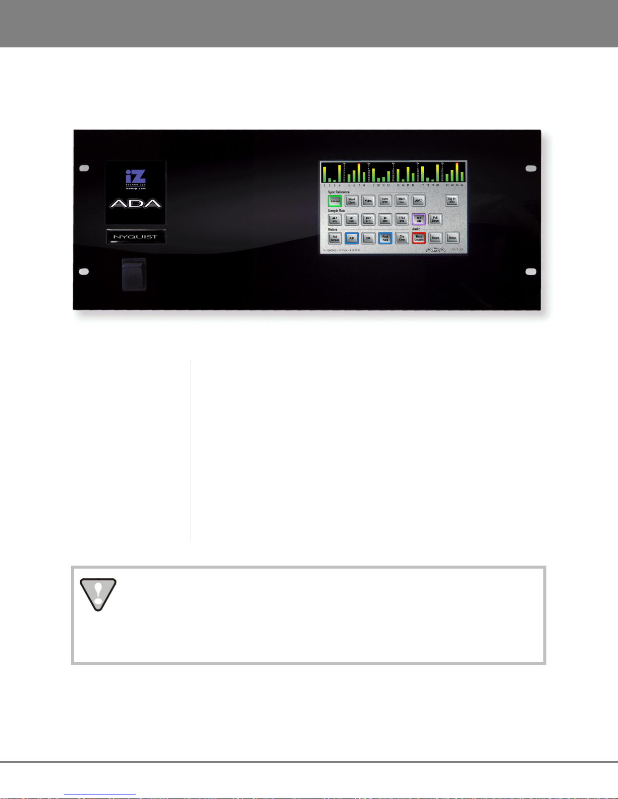
FRONT PANEL
ADA has a simple front panel layout containing only a power switch and LCD touchscreen.
ADA Front Panel Controls & Indicators
Power On/Off Switch
LCD Touchscreen
System software has been pre-installed on the internal hard disk. It is not necessary to reinstall the supplied system software. Please keep the supplied USB Flash Drive in a safe
place for software updates and in case it becomes necessary to re-install the system
software in the future.
ADA units have an unmarked momentary soft power switch. To turn ADA on,
push and release the top of the power switch briefly. To properly power down
ADA hold the top of the power switch for 5 seconds until ADA powers off. This
5 second delay is a safety feature that prevents inadvertent power down.
ADA units have an integrated 7” touchscreen that provides single touch
commands for most operations. I/O level information (Meters), Sync Source
selection, Sample Rate selection, I/O Routing Configuration and System
Configuration can be viewed and configured using the touchscreen.
www.izcorp.com • 1.800.776.1356
Page 12

5
ADA
VERSION
1.0 INTRODUCTION
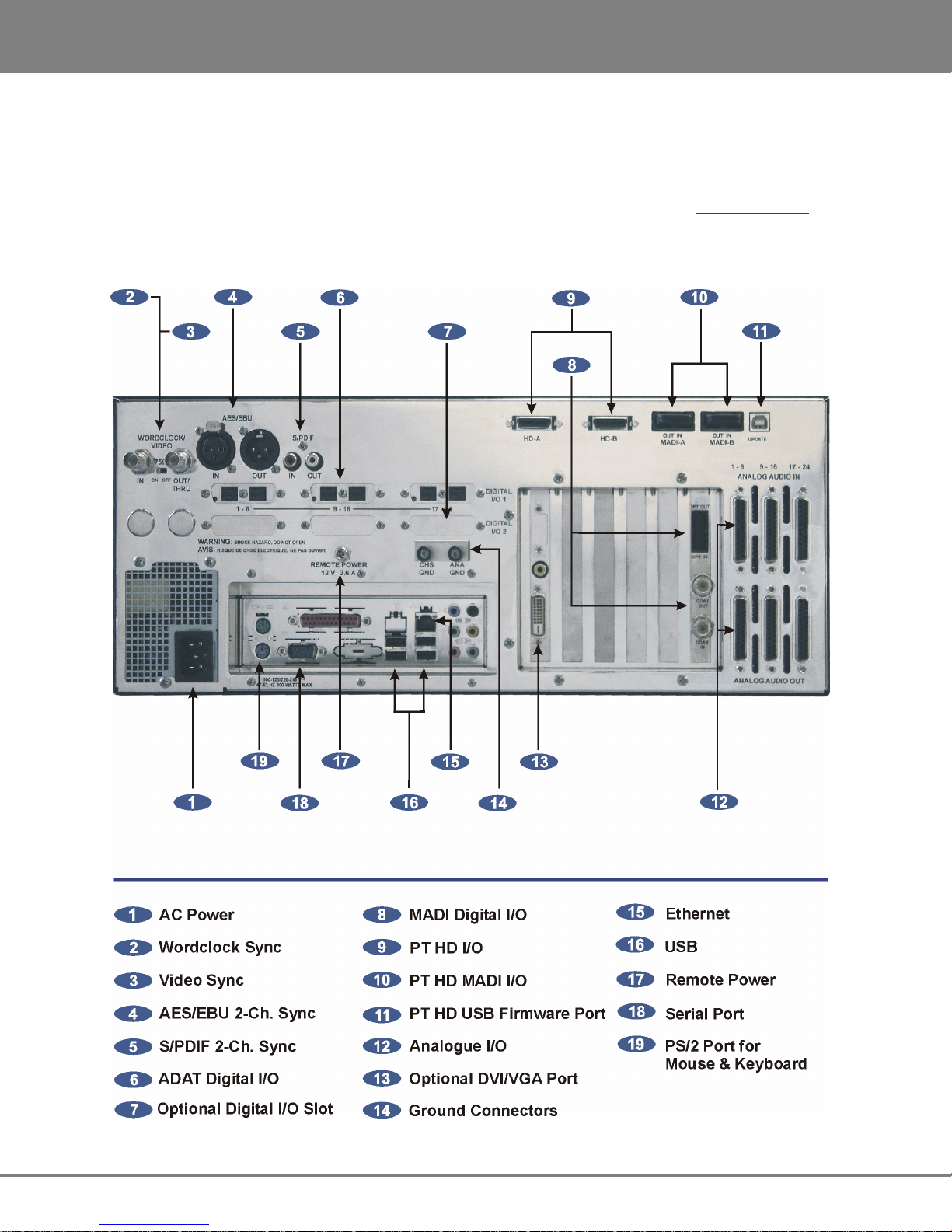
BACK PANEL
The back panel of ADA provides a wealth of professional sync and audio I/O options.
ADA Back Panel Labeling
(unit shown with optional ProTools HD Card and ADAT I/O)
Sync Reference
Sync reference signals are input via the Wordclock/Video, the 2-channel
AES/EBU or S/PDIF connector or the connectors of any installed multi-
channel digital I/O boards. See CONFIGURATION: SYNC REFERENCE for
detailed information.
Digital I/O
All ADA units are equipped with MADI format.
Optional multi-channel I/O cards are available for the ADAT Lightpipe
format, and ProTools HD. See CONFIGURATION: DIGITAL I/O for detailed
information.
Card Cage
The card cage contains the MADI connectors and optional VGA. See
SYSTEM SETUP: MAKING CONNECTIONS for detailed information.
Motherboard I/O
The motherboard includes onboard Gigabit Ethernet, (4) USB 2.0, (2) PS/2
connectors and (1) Serial remote port.
Analogue I/O
iZ Technology Corporation
The analogue I/O boards use six female 25-pin D-Sub connectors to
provide 24 channels of balanced audio I/O. See SYSTEM SETUP: MAKING
CONNECTIONS for detailed information.
Page 13
INTRODUCT
ION
ADA
VERSION
1.0
6
TOUCHSCREEN
ADA has an integrated 7” touchscreen that provides single touch commands and access to all of ADA’s
functions. ADA has 5 screen locations: Main Screen; Meters Screen; Routing Screen; Setup Screen; and
System Configuration Screen.
Main Screen
The Main Screen is the default screen, and is used for setting and viewing basic ADA parameters such as
SYNC REFERENCE, SAMPLE RATE and DIGITAL IN FORMAT. The Main Screen is the main portal for
entering ADA’s other screens.
www.izcorp.com • 1.800.776.1356
Page 14

7
ADA
VERSION
1.0 INTRODUCTION
Meters Screen
The Meters Screen displays all A/D and D/A meters on continuous LCD meters with a scale ranging from
below –60 to 0 dBFS (decibels Full Scale), which is the maximum input level.
Routing Screen
The Routing Screen allows user defined A/D and D/A routing.
iZ Technology Corporation
Page 15
INTRODUCT
ION
ADA
VERSION
1.0
8
Setup Screen
The Setup Screen allows access to menus for advanced and initial setup settings on ADA.
System Configuration Screen
The System Configuration Screen is used to view ADA’s hardware and software.
www.izcorp.com • 1.800.776.1356
Page 16

ADA
9
Version 1.0
TM
SECTION 2
SYSTEM SETUP
This section of the manual will help get ADA up and running as quickly as possible; it covers physical
installation, making cable connections, and ProTools software setup.
INSTALLATION
Once the ADA is unpacked please make sure to keep the box and all of the associated packaging
materials. In the event that the unit needs to be returned for service or repair, the use of the original
shipping box will ensure that ADA returns to iZ in good condition.
Make sure to consider the following before installation:
• Leave space around the front and the rear of the ADA to allow adequate air circulation.
• MADI digital lines can be run at a length of approximately 2000 meters with quality cabling.
• AES/EBU digital lines extension cable can be run at a length of approximately 33 meters.
_______________________________________
__________________________________
• ADAT optical digital audio connections can be run at a length of approximately 10 meters.
• The maximum PT HD DigiLink cable lengths are as follows:
48 kHz operation: 180 cm (6')
96 kHz operation: 90 cm (3')
192 kHz operation: 45 cm (1.5')
• If using the optional VGA Port, a VGA monitor and a high quality VGA extension cable will be
required.
• Make sure that the ADA has a reliable, properly grounded AC power source. An Uninterruptible
Power Supply (UPS) is highly recommended.
iZ Technology Corporation
Page 17
SYSTEM SETUP
ADA VERSION 1.0
10
MAKING CONNECTIONS
High quality cabling can be obtained through a local dealer or from iZ Technology. Wiring diagrams for
interfacing ADA are available on the Support section of the iZ Technology website at www.izcorp.com.
________________________________
ADA BACK PANEL
www.izcorp.com • 1.800.776.1356
Page 18
ADA VERSION 1.0
SYSTEM SETUP
11
1 AC POWER
Connect ADA to the AC mains using the supplied power cord. The power switch is located on the left side
of the front panel. See INTRODUCTION: OVERVIEW: FRONT PANEL.
The Power Supply in the ADA will internally auto-switch depending on the voltage output in
one’s region.
2 WORDCLOCK SYNC
The WORDCLOCK / VIDEO IN BNC connector accepts either a wordclock or a video sync source using
a coaxial cable.
Wordclock is a clock signal running at the same frequency as the sampling frequency of the digital audio
being converted. Syncing enables multiple digital devices to be locked together so that audio can be
reproduced, transferred and recorded without any digital noise or interference.
Wordclock signal supplied to the WORDCLOCK / VIDEO IN can be passed on to other devices using the
WORDCLOCK / VIDEO OUT/THRU connector. In situations where ADA should act as the clock master,
wordclock can also be output from the WORDCLOCK / VIDEO OUT/THRU connector. The function of the
OUT/THRU connector can be changed in the MENUS / SYNC MENU / SYNC REF OUTPUT setting.
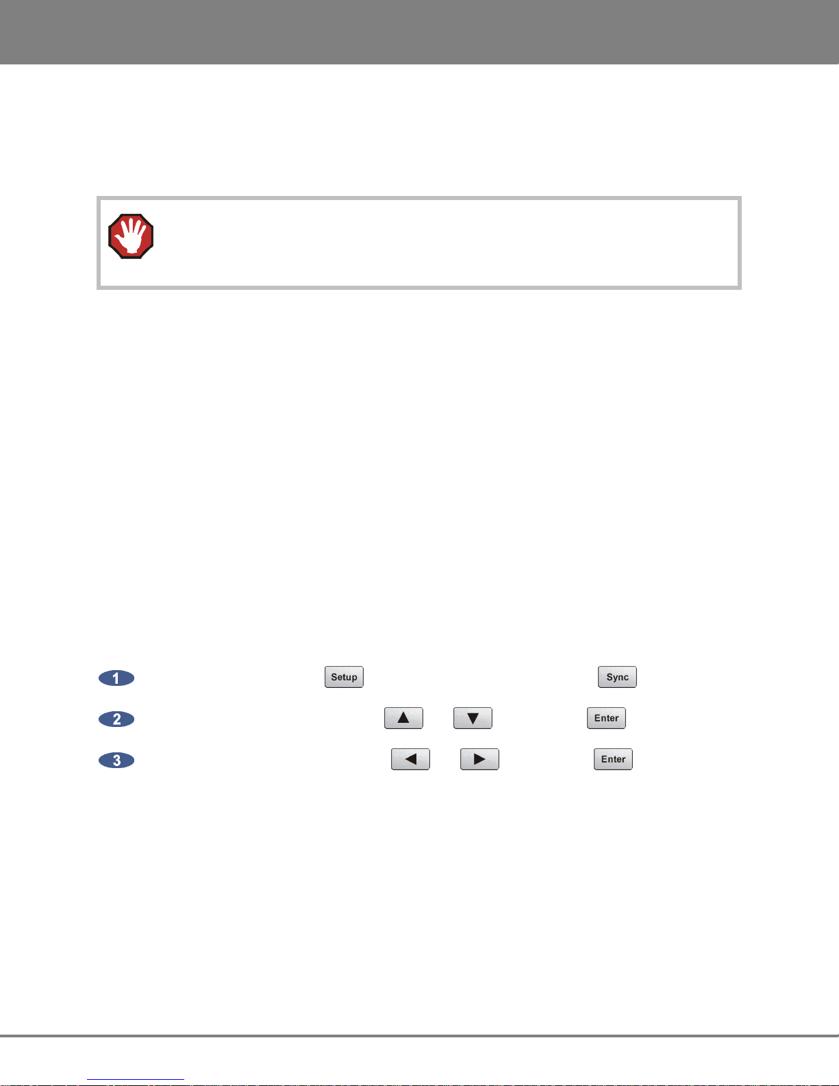
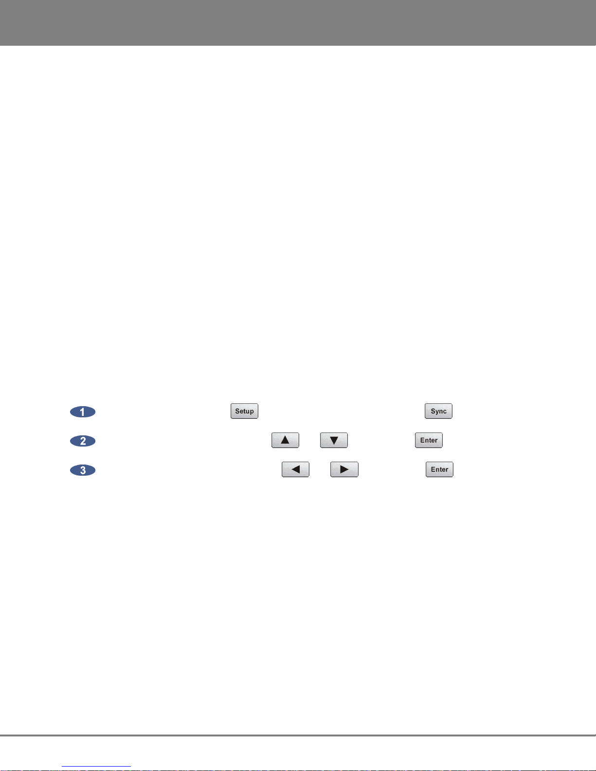
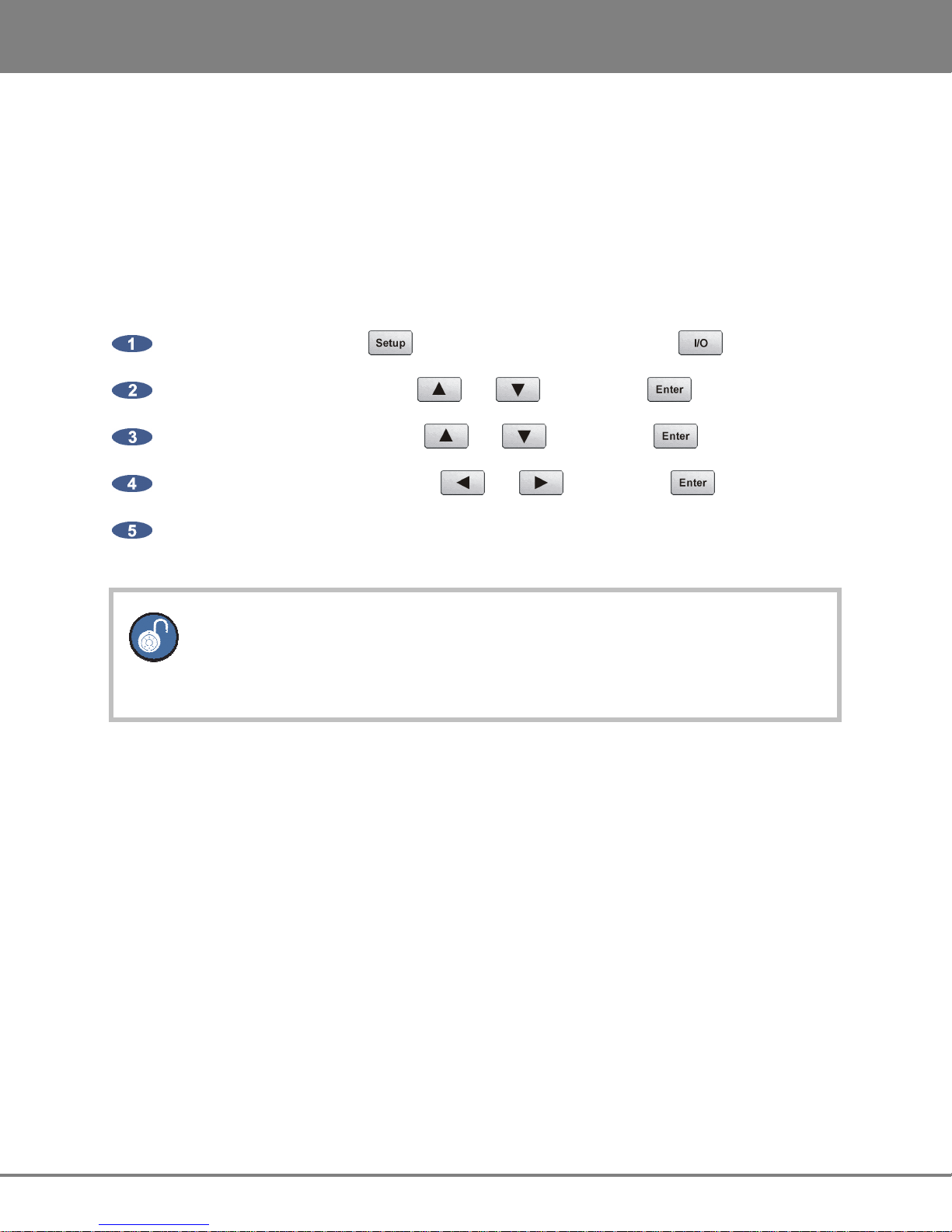
To switch between wordclock out and thru:
From the Main Screen press to enter the Setup Screen, then press .
Locate SYNC REF OUTPUT using the and
Choose WORDCLK or THRU using the and buttons. Press .
buttons. Press .
iZ Technology Corporation
Page 19
SYSTEM SETUP
ADA VERSION 1.0
12
3 VIDEO SYNC
Video sync, also known as house sync or black burst, is used to ensure a known and accurate
synchronization relationship exists between ADA and all the other devices in the studio, especially video
equipment.
If syncing the ADA to video, connect a proper 75-Ohm cable from the video source output to the
WORDCLOCK / VIDEO IN connector at the rear of the ADA.
The 75-Ohm switch provides video signal termination. This is only required to be ON if ADA is the last
device in a video signal chain where a video signal and video sync are in use on the same cable.
Termination does not affect the video sync signal. If termination is ON, it is active even when the ADA is
powered off.
4-5 AES/EBU 2-CHANNEL SYNC & S/PDIF 2-CHANNEL SYNC
The AES/EBU connectors or the S/PDIF connectors on the back panel are available to receive a clock
signal from a master clock or another digital audio device as well as transmit the master clock signal. Only
one set of connectors is enabled at a time.
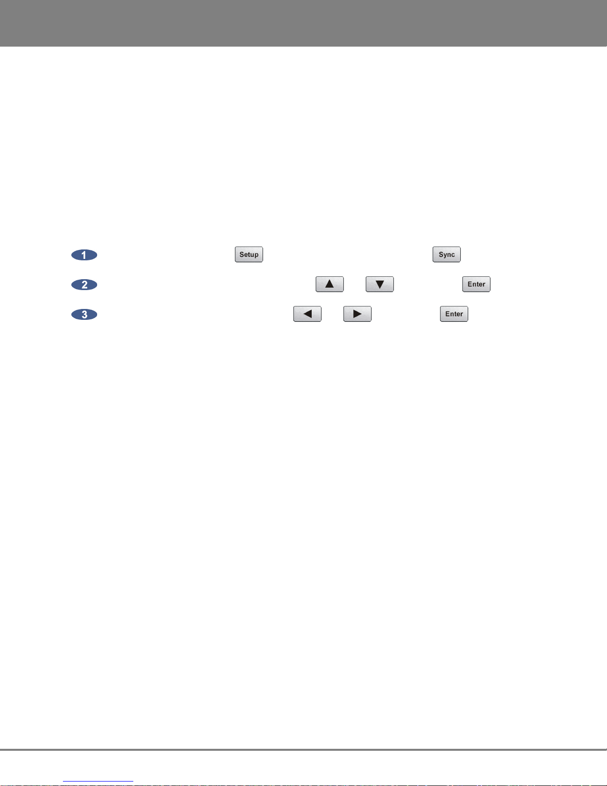
To switch between AES/EBU 2-Channel and S/PDIF 2-Channel:
From the Main Screen press to enter the Setup Screen, then press .
Locate DIG 2-CH OUTPUT using the and
Choose AES/EBU or S/PDIF using the and buttons. Press .
6 ADAT DIGITAL I/O OPTION CARD
ADAT Lightpipe is a standard for the transfer of digital audio via Toslink optical cables. The ADAT Digital
I/O Card features:
• Audio and sync data streams
buttons. Press .
• Digital audio transfers of 24 channels @ up to 48 kHz.
• Connectivity of 8 channels per Toslink optical cable.
• Maximum cable lengths of 10m
www.izcorp.com • 1.800.776.1356
Page 20
ADA VERSION 1.0
SYSTEM SETUP
13
ADAT Digital Audio
Lightpipe connections can be made with any optical fiber that is approved for use with the Alesis ADAT
system. Each fiber carries eight channels of digital audio. Three input and three output Lightpipe fibers
provide 24 channels of ADAT I/O at 48 kHz.
ADAT SYNC
The ADAT optical connectors on the rear panel can also be used to receive a clock signal from a master
clock or another digital audio device as well as to transmit a master clock signal.
If there are no ADAT cards installed an alert dialog will state: NO ADAT CARD
INSTALLED.
7 DIGITAL I/O OPTION SLOT
There are several digital I/O options available for ADA and each one has different cabling requirements.
8 MADI DIGITAL I/O
MADI (Multi-Channel Audio Digital Interface) is the standard digital I/O format on ADA. A fully professional
digital format, MADI features:
• Audio and sync data streams
• Digital audio transfers of 24 channels @ up to 96 kHz or 16 channels @ 192 kHz
• Single-cable connectivity
• Coaxial and optical connectors for increased cabling flexibility
• Maximum cable lengths of 200 meters (coaxial) and 2000 meters (optical)
MADI Digital Audio
The MADI format can transfer 24 channels of digital audio at sample rates of up to 96 kHz or 16 channels
at 192 kHz. Audio information is transferred through either MADI coaxial or MADI optical connectors. The
coaxial I/O uses a 75-Ohm, BNC terminated cable which has a maximum length of 200 meters. The
optical I/O uses a MADI optical cable which has a maximum length of 2000 meters.
iZ Technology Corporation
Page 21
SYSTEM SETUP
ADA VERSION 1.0
14
MADI Sync
MADI data streams include sync information. Sync information is transferred in the same way that audio
information is transferred – through either MADI coaxial or MADI optical connectors. The coaxial I/O uses
a 75-Ohm, BNC terminated cable which has a maximum length of 200 meters. The optical I/O uses a
MADI Optical cable which has a maximum length of 2000 meters. Either interface can be used to receive
a clock signal from a master clock or another digital audio source. Both MADI Optical and MADI Coaxial
will always output clock and data.
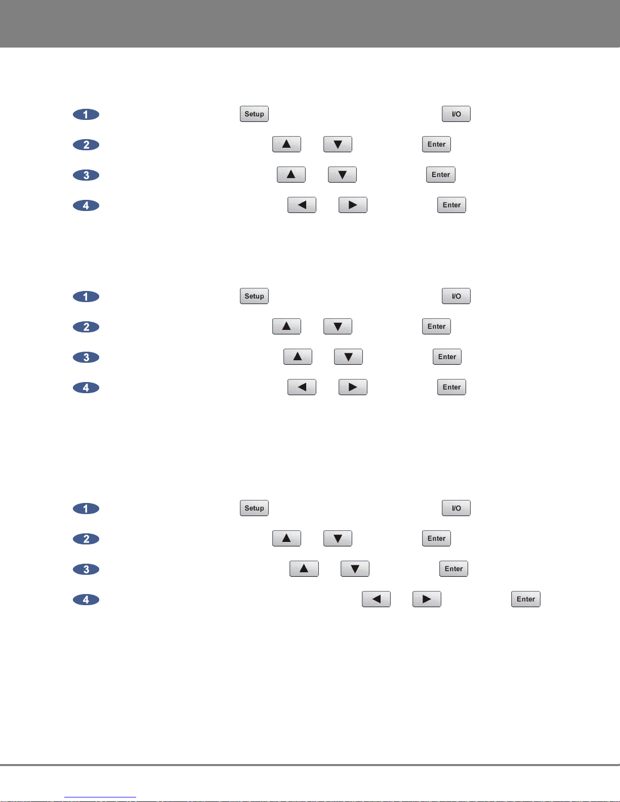
To switch between MADI Optical and MADI Coaxial Sync input format:
From the Main Screen press to enter the Setup Screen, then press .
Locate MADI COAX / OPTICAL IN using the and
buttons. Press .
Choose COAXIAL or OPTICAL using the and buttons. Press .
MADI Sample Rates and I/O Mapping High Speed Mode and SMUX Mode
Sampling frequencies of up to 48 kHz are designated as being in the NFS range (from NFs, Normal
Frequency sample). Sampling frequencies above 48 kHz and up to 96 kHz are in the "DFS range" (from
DFs, Double Frequency sample). Sampling frequencies above 96 kHz and up to 192 kHz are in the "QFS
range" (from QFs, Quadruple Frequency sample).
At high sample rates (i.e., sample rates in the DFS and QFS ranges), the MADI interface can operate in
either of two modes, High Speed (NATIVE) or SMUX 2 (LEGACY).
DFS Range (88.2 kHz to 96 kHz)
The MADI interface can operate in High Speed mode (NATIVE) or SMUX2 mode (LEGACY). In NATIVE
mode, the MADI-embedded reference signal has a frequency of 88.2 kHz to 96 kHz. In LEGACY mode,
the frequency is 44.1 kHz to 48 kHz.
QFS Range (176.4 kHz to 192 kHz)
The MADI interface can operate in High Speed mode (NATIVE) or SMUX2 (LEGACY) mode. In NATIVE
mode, the MADI-embedded reference signal has a frequency of 176.4 kHz to 192 kHz. In LEGACY
mode, the frequency is 88.2 kHz to 96 kHz.
www.izcorp.com • 1.800.776.1356
Page 22
ADA VERSION 1.0
SYSTEM SETUP
15
To switch ADA’s MADI I/O between High Speed mode (NATIVE) or SMUX2 mode (LEGACY) at 96 kHz:
From the Main Screen press to enter the Setup Screen, then press
Locate MADI SETTINGS using the and
Locate 96 kHz FRAMING using the and
buttons. Press .
buttons. Press .
.
Choose NATIVE or LEGACY using the and buttons. Press .
To switch ADA’s MADI I/O between High Speed mode (NATIVE) or SMUX2 mode (LEGACY) at 192 kHz:
From the Main Screen press to enter the Setup Screen, then press
Locate MADI SETTINGS using the and
Locate 192 kHz FRAMING using the and
buttons. Press .
buttons. Press .
.
Choose NATIVE or LEGACY using the and buttons. Press .
192 kHz Channels
The MADI format can transfer 16 (EXTENDED) or 12 (STANDARD) channels at 192 kHz
To switch ADA’s MADI I/O between 16 (EXTENDED) or 12 (STANDARD) channels at 192 kHz:
From the Main Screen press to enter the Setup Screen, then press
Locate MADI SETTINGS using the and
Locate 192 kHz CHANNELS using the and
buttons. Press .
buttons. Press .
.
Choose 16 (EXTENDED) or 12 (STANDARD) using the and buttons. Press .
iZ Technology Corporation
Page 23
SYSTEM SETUP
ADA VERSION 1.0
16
9-11 iZ DUAL PROTOOLS HD INTERFACE
The optional iZ Dual ProTools HD Interface allows multi-channel audio transfer directly to and from the
ProTools HD core card. Audio is transferred using DigiLink cables and is clocked through any SYNC
REFERENCE on ADA. The iZ Dual ProTools HD Interface does not contain any sync information. The iZ
Dual ProTools HD Interface has the following ports:
9. ProTools HD I/O port x 2
10. ProTools HD MADI optical I/O port x 2
11. ProTools HD USB firmware port x 1
9 ProTools HD I/O
The iZ Dual ProTools HD Interface allows multi-channel audio transfer directly to and from ProTools
HD. The maximum DigiLink cable lengths are as follows:
48 kHz operation: 180 cm (6')
96 kHz operation: 90 cm (3')
192 kHz operation: 45 cm (1.5')
In a typical setup, connect the Primary Port A of the iZ Dual ProTools HD Interface to the Primary Port
of the HD Core card with a DigiLink cable. Connect Primary Port B of the iZ Dual ProTools HD Interface
to the Primary Port of the first HD Accel card in the HD system with a DigiLink cable.
Technically, any Primary Port of the iZ Dual ProTools HD Interface is compatible with any Primary Port
of a ProTools HD system. However, connecting Primary Ports A and B of the iZ Dual ProTools HD
Interface to consecutively numbered Primary Ports of the ProTools HD system is preferable in order to
maintain clarity when working in the I/O Setup page of the ProTools or ADA software.
For ProTools software setup instructions, see PROTOOLS SOFTWARE SETUP, at the end of this section.
The iZ Dual ProTools HD Interface HD-B port is used to output a second ADA for an
additional 24 I/O to ProTools.
Do not connect or disconnect the iZ Dual ProTools HD Interface to/from the
ProTools cards while the ProTools software is running.
www.izcorp.com • 1.800.776.1356
Page 24
ADA VERSION 1.0
SYSTEM SETUP
17
10 ProTools HD MADI I/O
There are two optical MADI I/O ports on the iZ Dual ProTools Option Card: MADI A and MADI B. Connect
the iZ Dual ProTools HD Interface MADI A Optical In port to the ADA MADI digital I/O Optical Out port
and connect the iZ Dual ProTools HD Interface MADI A optical OUT port to the ADA MADI digital I/O
optical IN port.
The iZ Dual ProTools HD Interface MADI B optical port is used to connect a second
ADA unit’s MADI ports for an additional 24 I/O out of the HD-B port.
The Optical MADI I/O between the ADA MADI card and the iZ Dual ProTools HD
Interface must be connected for the iZ Dual ProTools HD Interface to function.
11 ProTools HD USB Firmware Port
The ProTools HD USB firmware port is provided for future ADA functionality and compatibility.
ProTools HD Sample Rates and I/O Mapping High Speed Mode and SMUX Mode
Sampling frequencies up to 48 kHz are designated as being in the "NFS range" (from NFs, Normal
Frequency sample). Sampling frequencies above 48 kHz and up to 96 kHz are in the "DFS range" (from
DFs, Double Frequency sample). Sampling frequencies above 96 kHz and up to 192 kHz are in the "QFS
range" (from QFs, Quadruple Frequency sample).
At high sample rates (i.e., sample rates in the DFS and QFS ranges), the ProTools HD Interface can
operate in either of two modes, High Speed (NATIVE) or SMUX 2 (LEGACY).
DFS Range (88.2 kHz to 96 kHz)
The iZ Dual ProTools HD Interface can operate in High Speed mode (NATIVE) or SMUX2 (LEGACY)
mode. In NATIVE mode, the iZ Dual ProTools HD Interface embedded reference signal has a frequency
of 88.2 kHz to 96 kHz. In LEGACY mode, the frequency is 44.1 kHz to 48 kHz.
iZ Technology Corporation
Page 25
SYSTEM SETUP
ADA VERSION 1.0
18
QFS Range (176.4 kHz to 192 kHz)
The iZ Dual ProTools HD Interface can operate in High Speed mode (NATIVE) mode only. In NATIVE
mode, the iZ Dual ProTools HD Interface embedded reference signal has a frequency of 176.4 kHz to
192 kHz.
To switch ADA’s iZ Dual ProTools HD Interface between High Speed mode (NATIVE) or SMUX2 mode
(LEGACY) at 96 kHz:
From the Main Screen press to enter the Setup Screen, then press
Locate MADI SETTINGS using the and buttons. Press .
Locate 96 kHz FRAMING using the and buttons. Press .
Choose NATIVE or LEGACY using the and buttons. Press .
In ProTools Software, go to Hardware Setup and select the ANALOG OUT 1-8 tab. Set Output
Trims on Channel 3 to either High Speed mode (NATIVE) (B) or SMUX2 mode (LEGACY) (A)
To change between High Speed mode (NATIVE) or SMUX2 (LEGACY) mode at 96 kHz
on ProTools software, see the section REMOTE CONTROL OF PROTOOLS HD INTERFACE
SETTINGS
12 ANALOGUE I/O
.
Analogue cables for ADA use the Tascam format, and share the same wiring scheme as analogue cables
for Digidesign’s ProTools and other popular modular digital multi-track recorders. The ADA end of each
analogue cable is a 25-pin D-sub connector that carries eight independent, balanced, line level audio
signals. Six cables will be required for a 24 Channel ADA system, three for input and three for output.
The other end of each analogue cable typically breaks out to individual XLR or TRS connectors for
connection to a console’s Tape Inputs and Buss Outputs. Another often-used approach is to wire directly
into a patch bay for the ultimate in routing flexibility.
www.izcorp.com • 1.800.776.1356
Page 26
ADA VERSION 1.0
SYSTEM SETUP
19
13 OPTIONAL DVI/VGA PORT
Any standard VGA monitor can be attached directly to the ADA. The monitor connection is a 15-pin D-sub
connector located on the far left of the card cage section on the back panel.
The default resolution is 800 x 480
Only the VGA DB-15 output is active. The S-Video and DVI outputs are not active.
14 GROUND CONNECTORS
These ground posts may be needed in situations where AC power is not properly grounded. Otherwise
they do not need to be connected.
15 ETHERNET
ADA ships with a Gigabit Ethernet port built into the Motherboard which can be used to update software
and for network control via a Mac or PC. Use any standard Ethernet cable for connecting ADA directly to
a PC/MAC or to a networked router.
16 USB
ADA ships with 4 USB 2.0 ports built into the Motherboard. These USB ports are used for connecting the
iZ Software USB key for software updates or saving debug logs. The USB ports can also be used for
connecting a mouse or keyboard. Please note that the ADA’s USB ports cannot be used for inputting
digital audio data.
17 REMOTE POWER
This barrel connector is included for future ADA functionality.
18 SERIAL PORT
This 9-pin connector allows for serial port connectivity for future ADA functionality.
19 PS/2 PORTS
Connect any standard PS/2 mouse or keyboard to ADA using the PS/2 mouse and keyboard ports.
iZ Technology Corporation
Page 27
SYSTEM SETUP
ADA VERSION 1.0
20
PROTOOLS SOFTWARE SETUP
The iZ Dual ProTools HD Interface can work with ProTools HD systems running on a Windows PC or
Mac OS X computer. Using the iZ Dual ProTools HD Interface with ProTools software is generally
straightforward. However, there are a few points to be aware of:
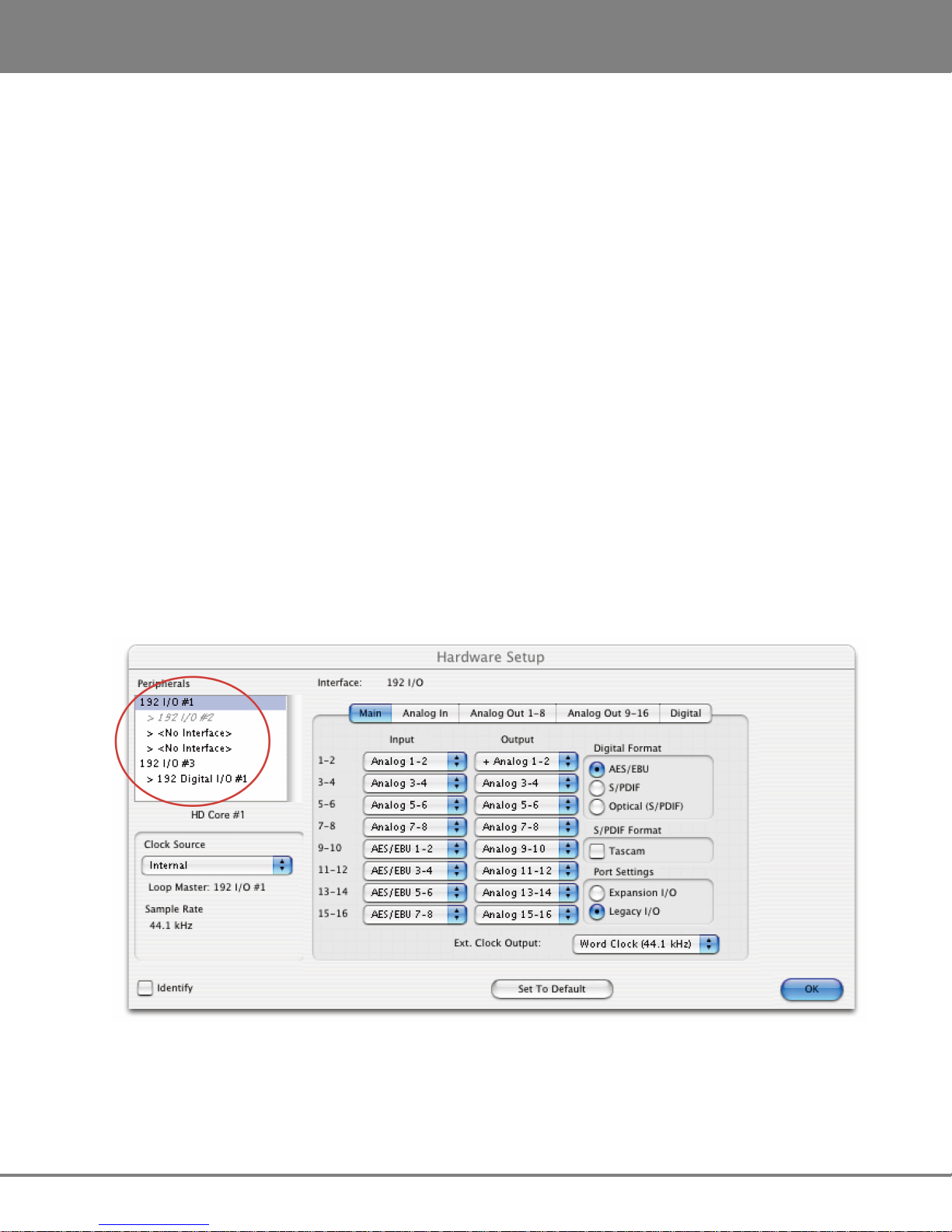
• The ADA appears in the ProTools software as four Digidesign 192 I/O units, except when operating
at 176.4 or 192 kHz, in which case it appears as two Digidesign 192 I/O units.
• The ADA analogue inputs and outputs appear in the ProTools software as analogue or digital
(AES/EBU or ADAT) inputs and outputs belonging to these four Digidesign 192 I/O units. Therefore,
no ADA-specific inputs or outputs will be listed in the Hardware Setup page of the ProTools
software under MENU/SETUP/HARDWARE. Please use the inputs and outputs that are listed,
regardless of their denomination — they are really the ADA inputs and outputs — and do not select
NONE.
The screenshot below was made using a ProTools HD2 system with a single iZ Dual ProTools HD
Interface. It shows as 192 I/O peripherals (top left). All the inputs and outputs that are listed belong to this
___________________________
single unit:
www.izcorp.com • 1.800.776.1356
Page 28

ADA VERSION 1.0
SYSTEM SETUP
21
Remote Control of ProTools HD Interface Settings
Some iZ Dual ProTools HD Interface settings can be controlled via the ANALOG OUT tab on the
ProTools software's Hardware Setup window (MENU/SETUP/HARDWARE):
The OUTPUT TRIM settings are irrelevant to the iZ Dual ProTools HD Interface because its inputs and
outputs are all digital. Therefore, they can be used to set various iZ Dual ProTools HD Interface
parameters such as:
• MADI number of channels 56/28/14 64/32/16
• MADI NFS mode Normal Special
• MADI DFS/QFS mode SMUX High Speed
• Wordclock input/Wordclock Frame Clock (48 kHz /44.1 kHz)
• Sample rate deviation Narrow (*1) Wide (*2)
(*1) Narrow sample rate deviation: typically used for Audio editing. Correct sample rate when
within +/-0.5% (the Lock LED must be lit solid).
(*2) Wide sample rate deviation: typically used for Video editing. Correct sample rate when within
+/-4.2% (the Lock LED must be lit solid). When operating at 48/96/192 kHz, this positive deviation
can only be obtained when also operating with 56/28/14 MADI channels.
iZ Technology Corporation
Page 29

SYSTEM SETUP
ADA VERSION 1.0
22
These options can be used to set various ADA’ s iZ Dual ProTools HD Interface parameters as follows:
Channel
Parameter If “A” is selected If “B” is selected
Number
1 Number of MADI channels 56/28/14 64/32/16
2 MADI NFS mode Normal Special
3 MADI DFS/QFS mode SMUX High Speed
4 Wordclock input Wordclock Frameclock (48 kHz /44.1 kHz)
Known Issues
When the ProTools software starts up, it uses the settings defined during the previous session, e.g.,
number and type of Audio Interfaces, I/O setup, etc.
If a Legacy Audio Interface (defined through MENU/ SETUP/HARDWARE) had been used, and then
replaced with the iZ Dual ProTools HD Interface, the ProTools software will display the following error
message…: DAE error -1125 was encountered
This is because the Legacy Audio Interface cannot be detected anymore. After clicking OK, the ProTools
software will close without allowing any change to the Hardware setup. An easy way to get around this
problem is to startup ProTools with the ADA switched OFF.
The following message will eventually be displayed: Unable to find an Audio Interface attached to...
At this point, power up the ADA and click OK. ProTools will then continue its start up procedure.
Another way to solve this problem is to delete the file DigiSetup.OSX and directory DAE
prefs in the Library\Preferences directory on your Mac. This will force ProTools to start up
using the default configuration (48 kHz, limited "Voices", no Hardware knowledge)
www.izcorp.com • 1.800.776.1356
Page 30

ADA VERSION 1.0
SYSTEM SETUP
23
Once ready, go to MENU/SETUP/HARDWARE and make sure all Legacy Interfaces are removed from
the PERIPHERALS list. The best way to do this is to click the name of a Legacy Audio Interface (e.g.,
882/20 or 888/24) and to select NO INTERFACES from the INTERFACE drop down box. After the
Legacy Interfaces have been removed, select the 192 I/O device, click the MAIN tab and select
EXPANSION I/O in the PORT SETTINGS section. The second 192 I/O device will appear in the
PERIPHERALS list.
iZ Technology Corporation
Page 31

SYSTEM SETUP
ADA VERSION 1.0
24
Playback Engine
The iZ Dual ProTools HD Interface provides up to 48 input and output channels using two ADA units.
Therefore, the number of voices for the Playback Engine may need to be increased. For instance, in
order to play back and record 64 tracks simultaneously at 96 kHz, go to MENU/SETUP/PLAYBACK
ENGINE and select 128 VOICES.
www.izcorp.com • 1.800.776.1356
Page 32

ADA
25
Version 1.0
TM
SECTION 3
CONFIGURATION
This section is a guide to configuring system settings and ensuring they are set correctly. Settings can
vary depending on the studio setup. The configuration settings covered in this section are: Operating
Level, Sample Rate, Sync Reference, Digital I/O, Networking, and Software.
OPERATING LEVEL
The input and output levels of ADA can be matched with the input and output levels of other pieces of
equipment in the studio. Although the inputs and outputs can be adjusted independently, all inputs share
the same operating level. The same holds true for all of the outputs.
Because a zero meter reading on a digital recorder represents the absolute maximum level (dBFS –
decibel Full Scale) that can be recorded, a much lower nominal level should be specified.
With analogue VU meters, 0 VU (+4dBu) represents this nominal level and above that is headroom, which
allows for dynamic surges and peak transients.
Setting ADA’s analogue audio input and output levels can be done by setting the level in dBu at which
_____________________________________
_________________________________
ADA will reach full scale (0 dBFS). It can also be set by the level in dBFS that a 0 VU (+4dBu) signal will
meter on ADA’s meters. The ANALOGUE I/O LEVEL dialog in the I/O MENU, will have a prompt of
either 0 dBFS or +4 dBu as the reference.
Choosing a reference of 0 dBFS will display a prompt for setting the full scale input and output levels (0
dBFS) as a dBu value between +18 and +24 dBu.
Choosing a reference of +4 dBu will display a prompt for setting where a signal at +4dBu will register on
ADA’s meters in dBFS. This will be a value between -14 and -20 dBFS. This value is commonly referred
to as headroom.
iZ Technology Corporation
Page 33

CONFIGURATION
ADA VERSION 1.0
26
To set the input and output operating levels:
From the Main Screen press to enter the Setup Screen.
Press then navigate to ANALOGUE LEVELS using and . Press .
Reference either 0 dBFS or +4 dBU using and . Press
Select the desired input operating level using and . Press
Select the desired output operating level use and . Press
If a reference of 0 dBFS is selected, the prompt will ask to set the full scale input and
output levels as a dBu value between +18 and +24 dBu.
If a reference of +4 dBu is selected, the prompt will ask to set the value between -14 and
-20 dBFS. This value is commonly referred to as headroom.
SAMPLE RATE
The Sample Rate in ADA must match the sample rates of the devices connected digitally to ADA. All ADA
units ship standard with a MADI Digital I/O Card; however, there are three Analogue I/O options. The
Classic, Nyquist and S-Nyquist analogue cards allow up to 48 kHz, 96 kHz, and 192 kHz sample rates
respectively. There can be up to three 8-channel analogue cards in ADA for a total of 24 channels of
_________________________________________
.
.
.
analogue I/O.
The standard sample rates available on ADA are: 44.1, 48, 88.2, 96, 176.4, and 192 kHz. ADA also
offers Pull Down sample rates for proper syncing to Video. Pull Down sample rates are: 44.056, 47.952,
88.112, 95.904, 176.224, and 191.808 kHz.
To set the Sample Rate in ADA:
From the Main Screen beneath the SAMPLE RATE header, press the desired sample rate button
selecting from
the selected sample rate button. Press the button again to confirm the selection. When locked,
the green ring around the selected button will be solid.
If the selected sample rate is not supported by the installed Analogue card(s), ADA will
switch to the Setup Screen and display the message NO ANALOG I/O AT XXX kHz.
Press the button to return to the Main Screen.
. A green ring will flash around
www.izcorp.com • 1.800.776.1356
Page 34

ADA VERSION
1.0
CONFIGURATION
27
To set the Pull Down sample rate in ADA:
From the Main Screen press the button. The available sample rates will switch to:
. Press the desired sample rate button. A
green ring will flash around the selected sample rate. Press the button again to confirm the
selection. When locked, the green ring around the selected button will be solid.
SYNC REFERENCE
_____________________________________
Sync (clock) reference is one of the keys to reliable digital audio interfacing. There are many possible
formats that can be used as ADA’s clock source. The sync format depends on which multi-channel digital
I/O card is installed in ADA. The available sync formats are displayed on the Main Screen, beneath the
SYNC REFERENCE heading.
The sync reference setting will vary widely depending on the application and the configuration of a
system. It will also depend on whether or not ADA is the master or slave in a particular setup. Access the
sync settings by pressing from the Setup Screen.
A reliable clock source is necessary for digital audio transfers to a digital mixer or to other digital audio
devices. Without proper data synchronization digital audio will exhibit pops, clicks and other undesirable
artifacts.
In a film or video post environment video sync is usually distributed to all the video, audio and clock
devices in the studio to ensure that everything is synchronous with the video signal right down to the
sample level.
To configure ADA as the digital audio sync master using the wordclock output:
Ensure that a wordclock cable is connected to the WORDCLOCK/VIDEO OUT/THRU connector.
From the Main Screen beneath the SYNC REFERENCE heading, press . A green ring will
flash around the button. Press the button again to confirm the selection. When locked, the green
ring around the button will be solid.
Press the button at the bottom left of the screen to enter the Setup Screen.
Press the button then navigate to SYNC REF OUTPUT using and .
Press .
Select WORDCLK using and . Press .
iZ Technology Corporation
Page 35

CONFIGURATION
ADA VERSION 1.0
28
To slave ADA to external wordclock:
Ensure that a wordclock source is connected to the WORDCLOCK/VIDEO IN connector.
From the Main Screen beneath the SAMPLE RATE heading, verify that the selected sample rate
matches the incoming wordclock frequency.
Beneath the SYNC REFERENCE heading, press . A green ring will flash around the button.
Press the button again to confirm the selection. When locked, the green ring around the selected
button will be solid.
If wordclock will be passing through the ADA make sure that the function of the OUT/THRU connector is
set to THRU.
To set ADA throughput external wordclock:
From the Main Screen press to enter the Setup Screen.
Press then locate SYNC REF OUTPUT using the and
Choose THRU using and . Press .
buttons. Press .
The wordclock frequency value is determined by the SAMPLE RATE set in the Main
Screen not the rate of the incoming wordclock signal.
When locked, the green ring around the selected SYNC REFERENCE button will be solid.
www.izcorp.com • 1.800.776.1356
Page 36

ADA VERSION
1.0
CONFIGURATION
29
To slave ADA to external video sync:
Ensure that a video sync source is connected to the WORDCLOCK/VIDEO IN connector.
From the Main Screen beneath the SAMPLE RATE heading, verify that the selected sample rate
matches the incoming audio sample rate.
Press the button at the bottom left of the screen to enter the Setup Screen.
Press the button then navigate to VIDEO FORMAT using and . Press .
Select either NTSC or PAL using and . Press .
From the Main Screen beneath the SYNC REFERENCE heading, press or
(depending which was selected in the previous step). A green ring will flash around the button.
Press the button again to confirm the selection. When locked, the green ring around the selected
button will be solid.
The video sync frequency value is determined by the VIDEO RATE set in the SYNC
MENU not the rate of the incoming video sync signal.
To slave ADA to an external AES/EBU clock source:
Connect an AES/EBU source to the AES/EBU IN connector using an XLR terminated digital
audio cable.
From the Main Screen press to enter the Setup Screen.
Press then navigate to DIG 2-CH FORMAT using and . Press .
Select AES/EBU using and . Press .
From the Main Screen beneath the SYNC REFERENCE heading, press . A green ring will
flash around the button. Press the button again to confirm the selection. When locked, the green
ring around the selected button will be solid.
iZ Technology Corporation
Page 37

CONFIGURATION
ADA VERSION 1.0
30
To slave ADA to an external S/PDIF clock source:
Connect the S/PDIF source to the S/PDIF IN connector using an RCA terminated digital audio
cable.
From the Main Screen press to enter the Setup Screen.
Press then navigate to DIG 2-CH FORMAT using and . Press .
Select S/PDIF using and . Press .
From the Main Screen beneath the SYNC REFERENCE heading, press . A green ring will
flash around the button. Press the button again to confirm the selection. When locked, the green
ring around the selected button will be solid.
To slave ADA to an external ADAT clock source:
Connect the ADAT source to the desired optical ADAT IN connector using a light pipe cable.
From the Main Screen beneath the SYNC REFERENCE heading, press
. A green ring will
flash around the button. Press the button again to confirm the selection. When locked, the green
ring around the selected button will be solid.
If ADAT cards are not installed then a dialog will display: NO ADAT CARD INSTALLED.
To slave ADA to an external MADI clock source:
Connect the MADI source to either the BNC or the OPTICAL CABLE connector using the
appropriate digital audio cable.
Press the button at the bottom left of the screen to enter the Setup Screen. Press the
button then navigate to MADI COAX/OPT IN using and . Press .
Select either COAX or OPTICAL using and . Press .
From the Main Screen beneath the SYNC REFERENCE heading, press
(depending which was selected in the previous step). A green ring will flash around the button.
Press the button again to confirm the selection. When locked, the green ring around the selected
button will be solid.
www.izcorp.com • 1.800.776.1356
or
Page 38

ADA VERSION
1.0
CONFIGURATION
31
DIGITAL I/O
_________________________________________
The digital I/O formats available for selection will depend on the type and number of digital interface
options installed in ADA. All units ship with multi-channel MADI digital I/O. The 24 channel digital I/O
options available include: ADAT, and ProTools HD
It is important to note that once a digital format is selected, an appropriate clock source must be selected
as well. Many times they are one and the same thing, but not always. For instance, a MADI transfer may
be required but the sync reference for all digital devices in the studio may be a wordclock generator
referenced to video sync. ADA may also act as clock master and all other digital equipment will clock to
ADA in which case SYNC REFERENCE would be set to internal.
MADI
Each BNC connector or Optical connector carries 24 channels of audio. You must choose either
COAXIAL or OPTICAL under DIG IN depending on the inputs/outputs of the external device. This
format is unidirectional so one input and one output MADI cable will be required for 24 channels of
MADI I/O.
To select MADI as the digital I/O format:
Make sure that all cabling is connected properly.
From the Main Screen press the button (MADI is displayed by default).
Select MADI as the digital format using and . Press .
Select OPTICAL or COAXIAL using and . Press .
ADAT
Lightpipe optical fibers carry eight channels of digital audio. This format is unidirectional so three input
and three output Lightpipe “cables” will be required for 24 channels of ADAT I/O.
To select ADAT as the digital I/O format:
Make sure that all cabling is connected properly.
From the Main Screen press the button (MADI is displayed by default).
Select ADAT as the digital format using and . Press .
iZ Technology Corporation
Page 39

CONFIGURATION
ADA VERSION 1.0
32
iZ Dual ProTools HD Interface
This option allows multi-channel audio transfer directly to and from a ProTools HD core card. Audio is
transferred using DigiLink cables and clocked through any sync reference on ADA. The iZ Dual ProTools
HD Interface does not contain any sync information.
To select Pro Tools HD as the digital I/O format:
Make sure that all cabling is connected properly.
From the Main Screen press the button (MADI is displayed by default).
Select PT HD VIA MADI as the digital format using and . Press .
NETWORKING
________________________________________
ADA ships with a Gigabit Ethernet interface built onto the motherboard. This allows for ADA software
updates and debug logs to be sent through the network.
The goal of ADA networking is to configure the unit for integration into an existing network or for
connection to a personal computer. Networking can be very extensive; this section of the manual only
addresses basic networking configuration settings to be used with ADA. Please refer additional
networking questions to the iZ Support department.
DISCLAIMER: iZ Technology cannot offer advice on networking and security issues that
do not directly pertain to the ADA system. For further assistance please consult a
networking professional or make use of the extensive resource materials available on the
Internet.
ADA IP Address Setup
ADA can connect to a PC or Mac via Ethernet with the appropriate cabling and software.
To setup ADA for networking:
From the Main Screen press to enter the Setup Screen, then press .
Navigate to NETWORK PREFS using and . Press . Select INTERFACE
PREFS. Press
www.izcorp.com • 1.800.776.1356
Page 40

ADA VERSION
1.0
CONFIGURATION
33
At the INTERFACE PREFS: dialogue, select HOST NAME using and .
Press .
At the HOST NAME: prompt, use a QWERTY keyboard to enter a unique name for ADA.
Press .
At the DHCP SERVER: dialogue, ENABLE or DISABLE DHCP using and . Press
. If DHCP is enabled, steps 6-11 can be skipped. Do NOT enable DHCP when using a
crossover cable to connect directly with a Mac or Windows-based computer.
At the LOCAL IP ADDRESS: prompt, enter a unique IP address using the numeric keypad
displayed on the screen and and . Press . When using a crossover cable to
connect directly with a Windows or Mac-based computer, ADA’s IP address should have the
same first three numbers but the last number has to be different. E.g., Windows computer IP is
192.168.1.1 therefore the ADA IP can be 192.168.1.2 or 192.168.1.3 or 192.168.1.4, etc.
The Internet Assigned Numbers Authority has set certain IP address ranges for use in private
networking applications:
Class A 10.0.0.0—10.255.255.255
Class B 172.16.0.0—172.31.255.255
Class C 192.168.0.0—192.168.255.255
In a self-contained peer-to-peer network that never sees the outside world any IP address range
may be used. However, care should be taken when assigning IP addresses to avoid potential
security risks and IP address conflicts. For further information visit the Internet Assigned Numbers
Authority site at http://www.iana.org.
At the SUBNET MASK: prompt, enter a SUBNET MASK value using the numeric keypad and
and . Press . The standard default is 255.255.255.0. The SUBNET MASK
value must match the subnet mask value of the computer/server the ADA is connecting to.
A GATEWAY entry is only required when connected to a WAN (wide area network) such as the
Internet. At the GATEWAY: prompt, enter a gateway IP address using the numeric keypad and
and Press .
iZ Technology Corporation
Page 41

CONFIGURATION
ADA VERSION 1.0
34
The PRIMARY DNS address for the server is only required for connecting to a client-server
network. At the PRIMARY DNS: prompt, enter a PRIMARY DNS value using the numeric
keypad and and . Press .
The SECONDARY DNS address only applies if there is a secondary server on a client-server
network. At the SECONDARY DNS: prompt, enter a SECONDARY DNS value using the numeric
keypad and and . Press .
The SMTP HOST setting is sometimes required to allow email of debug logs via a specific
Internet Service Provider. At the SMTP HOST: prompt, type a SMTP HOST using a QWERTY
keyboard (i.e. mail.smtp.com).
FTP
FTP stands for File Transfer Protocol. It is used to transfer data from one computer to another.
ADA has a built in FTP (File Transfer Protocol) client. This feature enables ADA software updates from
PC, Mac or iZ Technology’s website.
ADA FTP Client Network Setup with Windows 2000/XP/Vista Server
For Mac setup instructions skip to the next section.
These instructions are for setting up a Network between ADA and a PC (Windows).
ADA has a built-in FTP Client . PC computers, however, do not generally come with installed FTP Client
or FTP Server programs. In order to network ADA, 3rd party FTP Client and FTP Server software must be
installed on the PC. Downloadable FTP software options include: FTP Server software: FileZilla Server
Software Updates via FTP will not be possible unless FTP Server software is installed on
the destination PC.
www.izcorp.com • 1.800.776.1356
Page 42

ADA VERSION
1.0
CONFIGURATION
35
Once the PC has been equipped with an FTP Server, connect an Ethernet crossover cable between ADA
and the PC. Crossover cables are available at most computer stores. A crossover Ethernet cable is
different from a standard (straight through) Ethernet cable, as the crossover cable has different wiring.
Crossover cables are usually yellow in colour. If ADA and the PC are connected through a router,
standard Ethernet cables may be used. ADA can also be integrated into a network environment; contact
the network administrator for specific settings.
PC IP Address and Firewall setup for Windows Vista:
Click the START menu and click CONTROL PANEL.
Click on WINDOWS FIREWALL then click the GENERAL TAB shut off the Firewall and click the
OK button.
In the CONTROL PANEL click on NETWORK AND INTERNET, then NETWORK AND
SHARING CENTER and click to select MANAGE NETWORK CONNECTIONS from the list of
tasks.
Right click on LOCAL AREA CONNECTION and choose PROPERTIES.
Select USE THE FOLLOWING IP ADDRESS and enter a unique IP Address (i.e. 192.168.12)
For SUBNET MASK enter: 255.255.255.0.
Leave all other fields blank.
Click the OK button.
PC IP Address and Firewall setup for Windows XP:
Click the START menu and click CONTROL PANEL.
Click on WINDOWS FIREWALL then click the GENERAL TAB shut off the Firewall and click the
OK button.
Click on NETWORK CONNECTIONS in CONTROL PANEL.
Right click on LOCAL AREA CONNECTION and choose PROPERTIES.
Click on INTERNET PROTOCOL (TCP/IP) and then click PROPERTIES.
Click USE THE FOLLOWING IP ADDRESS and enter a unique IP Address (i.e. 192.168.1.2).
For SUBNET MASK enter: 255.255.255.0
Leave all other fields blank.
Click the OK button.
iZ Technology Corporation
Page 43

CONFIGURATION
ADA VERSION 1.0
36
PC FTP Server Username and Password:
Open FTP Server.
Click on EDIT then click USERS.
Click the GENERAL tab and then click ADD.
Type in a username and password.
Click the SHARED FOLDERS tab and add a drive or directory to import/export to.
Highlight the DIRECTORY added and check all the boxes under FILES AND DIRECTORIES.
ADA FTP client setup:
Press from the Main Screen and press . Use and and press on
NETWORK PREFS then again on SERVER PREFS.
At the NETWORK PROTOCOL: prompt, press the on FTP.
At the SERVER IP ADDR: prompt, use the numeric keypad displayed on the ADA screen and
and to enter the PC’s server IP address and press . (i.e. 192.168.1.2)
At the SERVER NAME: prompt, use a QWERTY keyboard to enter a name for the FTP Server.
(i.e. Win XP) (Note: This is display only, and should not impact functionality.)
At the SAVE CHANGES: prompt, press on YES.
Once FTP/CIFS Server Information has been entered it is a good idea to test the
connection. From the Main Screen press and then press . Use and
to select PING IP ADDRESS and press . This provides a way to test
communication by sending small packets of data across the network. By default the
SERVER IP will be entered in this field. Press at the PING IP ADDRESS: prompt.
REPLY RECEIVED means the Server is reachable. If the message NO REPLY is
displayed, recheck the networking settings on both the ADA and Server.
www.izcorp.com • 1.800.776.1356
Page 44

ADA VERSION
1.0
CONFIGURATION
37
ADA FTP Client Network Setup with a Mac OS X server
These instructions are for setting up a Network between ADA and a Mac (OS X). To use ADA’s FTP
client, a 3rd party FTP Server is recommended such as Pure FTP Manager. This allows greater flexibility
such as multiple users and unique paths.
Connect an Ethernet cable between ADA and the Mac. ADA can also be integrated into a network
environment; contact the network administrator for specific settings.
Mac IP Address setup:
Open SYSTEM PREFERENCES and then click on NETWORK.
At SHOW, select BUILT IN ETHERNET and select the TCP/IP tab.
At CONFIGURE IPV4: choose MANUALLY.
On IP ADDRESS enter a unique IP ADDRESS (i.e. 192.168.1.2).
For SUBNET MASK enter: 255.255.255.0
Click APPLY NOW.
Mac FTP Server setup:
Open SYSTEM PREFERENCES.
Click on SHARING.
Click on the SERVICES tab.
Click on the FTP check box.
Click on the FIREWALL tab.
Click the STOP button.
iZ Technology Corporation
Page 45

CONFIGURATION
ADA VERSION 1.0
38
Mac FTP Server Username and Password:
Open SYSTEM PREFERENCES.
Click on ACCOUNTS.
The FTP USER NAME is the MY ACCOUNT’S, SHORT NAME.
The FTP USER NAME is the MY ACCOUNT’S, PASSWORD.
ADA FTP client setup:
Press from the Main Screen and press . Use and and then press
on NETWORK PREFS then again on SERVER PREFS.
At the NETWORK PROTOCOL: prompt, press on FTP.
At the SERVER IP ADDR: prompt, use the numeric keypad displayed on the ADA screen and
the and to enter the PC’s server IP address and press . (i.e. 192.168.1.2)
At the SERVER NAME: prompt, use a QWERTY keyboard to enter a name for the FTP Server.
(i.e., Mac Pro) (Note: This is display only, and should not impact functionality.)
At the SAVE CHANGES: prompt, press on YES.
Once FTP/CIFS Server Information has been entered it is a good idea to test the
connection. From the Main Screen press and then press . Use and
to select PING IP ADDRESS and press . This provides a way to test
communication by sending small packets of data across the network. By default the
SERVER IP will be entered in this field. Press at the PING IP ADDRESS: prompt.
REPLY RECEIVED means the Server is reachable. If the message NO REPLY is
displayed, recheck the networking settings on both the ADA and Server.
www.izcorp.com • 1.800.776.1356
Page 46

ADA VERSION
1.0
CONFIGURATION
39
SOFTWARE
___________________________________________
Although ADA is shipped with the latest version of ADA software, it can be kept up to date by
downloading new versions of the software as they become available. iZ is constantly working to add new
features and to improve the performance and reliability of ADA. Software updates and downloading
instructions are available from the following: iZ website at www.izcorp.com, an iZ authorized dealer, and
iZ Technology.
Install Procedure
Copy the ADA_vX.X.X file installer to either a USB 2.0 (FAT 32) drive or to a N:Network drive.
From the Main Screen press to enter the Setup Screen, then press
Locate UPDATE SOFTWARE using and . Press
At the UPDATE S/W FROM: prompt, select either WEB:IZCORP.COM (WAN Access
Required), N:NETWORK or E:USB DRIVE using and .Press . If updating
through the web or USB Drive skip to step 7.
At the USER NAME: prompt, enter the PC/Mac’s FTP user name (case sensitive) using a
QWERTY keyboard.
At the USER PASSWORD: prompt, enter the PC/Mac’s FTP password (case sensitive).
Once connected, navigate to the ADA software installer file using
to back out of a folder level. Once in the appropriate folder, use the and to
to go into a folder, and
select ADA_vX.X.X and press to select the software installer file.
At the INSTALL VER X.XX?: prompt, select YES using and . Press .
+INSTALLING+ will display while the ADA application is being installed.
When REBOOT ADA TO COMPLETE INSTALL is displayed, power off ADA and power back on.
Once rebooted the software install will be complete.
iZ Technology Corporation
Page 47

CONFIGURATION
ADA VERSION 1.0
40
www.izcorp.com • 1.800.776.1356
Page 48

ADA
41
Version 1.0
TM
SECTION 4
OPERATIONS
This section of the manual provides information about operating and navigating through ADA’s
touchscreen interface.
POWERING ADA ON AND OFF
ADA units have an unmarked momentary soft power switch. To turn ADA on, push and release the top of
the power switch briefly. To properly power down ADA hold the top of the power switch for 5 seconds until
ADA powers off. This 5 second delay is a safety feature that prevents inadvertent power down.
When ADA powers up, a power on self test (POST) is performed, and proceeds to load the ADA
application. During the ADA application launch, the iZ logo will appear followed by a black screen for a
few seconds, followed by the ADAView operating screen.
ADAVIEW DISPLAY
__________________________
__________________________
___________________________________
With the built-in LCD touchscreen, ADA lets users control settings and preferences with a single touch.
As an option, ADA may be controlled remotely by attaching a VGA monitor and mouse using either the
USB or PS/2 ports.
ADAView has a total of six screens:
• Main Screen • Setup Screen
• Routing Screen • Meters Screen
• System Configuration Screen • Debug Screen
Each screen shows the ADA software version at the bottom right and the iZ Technology Support toll free
phone number (North America) at the bottom left.
iZ Technology Corporation
Page 49

OPERATIONS
ADA VERSION 1.0
42
MAIN SCREEN
The Main Screen is used for setting basic ADA parameters such as SYNC REFERENCE and SAMPLE
RATE; it is also used for selecting Meter views and preferences. The Main Screen is the main portal for
entering ADA’s other five screens.
________________________________________
GETTING TO THE MAIN SCREEN
The Main Screen is ADA’s default main screen – it is the screen that will be displayed upon ADA startup.
To get to the Main Screen:
• From the Setup Screen, press located at the bottom right of the screen.
• From the Routing Screen, press .
• From the Meters Screen, tap the screen once.
• From the System Configuration Screen, press
• From the Debug Screen, press
then .
then .
www.izcorp.com • 1.800.776.1356
Page 50

ADA VERSION 1.0
OPERATIONS
43
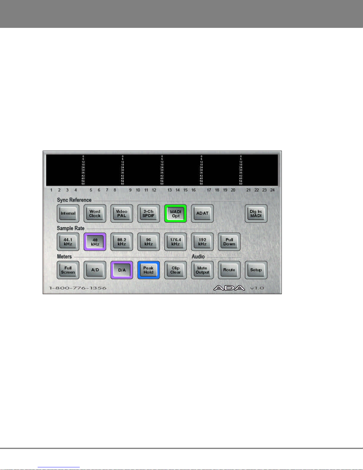
MAIN SCREEN SECTIONS
Sync Reference
Use the SYNC REFERENCE buttons to set the sync source on ADA. Select from ,
/ , /
and
. To set ADA’s SYNC REFERENCE:
Press the desired Sync Source button. A green ring will flash around the selected button.
Press the button again to confirm the selection. When locked, the green ring around the selected
Sync Source will be solid.
Dig In
Use the
shortcut button to select the digital format to be input into ADA.
Press to be taken directly to the DIGITAL IN menu on the Setup Screen.
Select the desired digital in format using and . Press .
Press located at the bottom right of the Setup Screen to return to the Main Screen.
Sample Rate
/
,
Use these buttons to set ADA’s sample rate. Select from , , , , and .
Press to select from the pull down sample rates of , , , , and
.
To use the SAMPLE RATE buttons:
Press the desired sample rate button. A purple light will flash around the selected button.
Press the button again to confirm the selection. When locked, the purple ring will be solid around
the selected sample rate.
To use the PULL DOWN SAMPLE RATE buttons:
Press the button. The SAMPLE RATE buttons will change to their pull down values.
Press the desired sample rate button. A purple light will flash around the selected button.
Press the button again to confirm the selection. When locked, the purple ring will be solid around
the selected sample rate.
iZ Technology Corporation
Page 51

OPERATIONS
ADA VERSION 1.0
44
Meters
Use these buttons to set ADA meter options. Use the , , , , and buttons to
set the viewing preferences for the D/A and A/D meters.
Press once to enter the Meters Screen. This screen displays both A/D and D/A meters
simultaneously. Tap the screen at anytime to return to the Main Screen.
Press once to view the A/D meters at the top of the Main Screen. When selected, a purple ring
will be solid around this button.
Press once to view the D/A meters at the top of the Main Screen. When selected, a purple ring
will be solid around this button.
Press once to enable peak hold on all meters. The maximum meter value will remain on the
displayed meters for the time designated in the Preferences menu. When selected, a blue ring
will be solid around this button.
Press once to clear the clip lights on the ADA meters. This is a momentary button and does not
lock.
Audio
Use the Audio buttons to control ADA’s audio signals.
Press once to mute all analogue inputs and outputs. When selected, a red ring will flash around
this button.
Press this button once to go directly to ADA’s Routing Screen. See Routing following for
operating instructions for the Routing page.
www.izcorp.com • 1.800.776.1356
Page 52

ADA VERSION 1.0
OPERATIONS
45
SETUP SCREEN
The Setup Screen is used for accessing ADA’s advanced settings and preferences via the ADA software
menus.
________________________________________
GETTING TO THE SETUP SCREEN
The Setup Screen is one of ADA’s three secondary level screens and is accessible from the Main Screen.
The Setup Screen is the portal screen for the System Configuration and Debug screens. To enter the
Setup Screen:
• From the Main Screen, press located at the bottom right of the screen.
• From the Routing Screen, press then .
• From the Meters Screen, tap the screen once to enter the Main Screen, then press .
• From the System Configuration Screen, press .
• From the Debug Screen, press .
iZ Technology Corporation
Page 53

OPERATIONS
ADA VERSION 1.0
46
MANUAL
SYSTEM MENU:
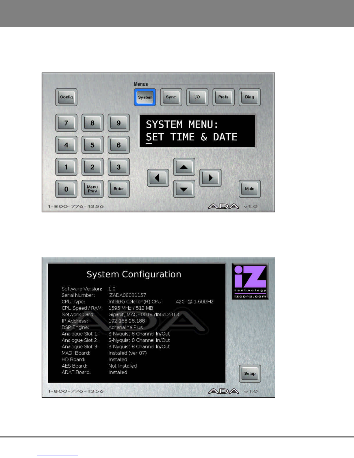
ADA SOFTWARE MENU OPTIONS
The Setup Screen allows users to navigate through ADA software’s menu tree and to set advanced
system preferences. ADA software has five main menus: SYSTEM, SYNC, I/O, PREFERENCES, and
DIAGNOSTICS. The main menus contain sub-menus, some containing multiple menu layers. Upon
arriving at the end of any given menu tree, the user will be prompted to enter a numeric value or to select
one of a number of given options. Values can be entered using any of ADA’s data entry methods
including the numeric keys, arrow keys or by using a standard PC keyboard.
Example:
From the Main Screen press SYSTEM.
SET TIME & DATE
Then press twice to access the
HELP within the SYSTEM MENU.
Finally, press to access the HELP
section.
For a complete ADA menu tree and an overview of each menu item, please go to the REFERENCE section.
SYSTEM MENU:
HELP
HELP DOCUMENTS:
SYSTEM MENU
This menu is used to access ADA system settings such as SET TIME & DATE, UPDATE SOFTWARE
and the HELP menu.
To access the SYSTEM MENU:
From the Setup Screen press .
Select the desired menu item using and . Press . Use and to
move between the menu fields of any given menu level. Use and or the numeric
keypad to change a given field’s value.
Press to confirm the selection.
Use the button to back out one level of any menu. See the REFERENCE section for
ADA Menu Tree.
www.izcorp.com • 1.800.776.1356
Page 54

ADA VERSION 1.0
OPERATIONS
47
To SET TIME & DATE:
From the Setup Screen press . Select SET TIME & DATE using and . Press
.
Use and to move between the fields. Use and or the numeric keypad
to change the field’s value.
Press to confirm the selection.
To UPDATE SOFTWARE: See CONFIGURATION: SOFTWARE
To access the HELP MENU:
From the Setup Screen press .
Select help using and . Press .
Select RELEASE NOTES or MANUAL using and . Press .
A PDF Viewer will open ADA RELEASE NOTES or MANUAL. Use a mouse or touchscreen to
navigate through the documents. Click or tap the iZ Logo in the top left hand corner of the screen
to return to ADA Setup Screen.
iZ Technology Corporation
Page 55

OPERATIONS
ADA VERSION 1.0
48
SYNC MENU
This menu is used to access ADA sync settings and preferences
To access the SYNC MENU:
From the Setup Screen press .
Select the desired menu item using and . Press .
MADI COAX/OPT IN Select this option to choose MADI COAX or MADI OPTICAL as the
digital in format.
VIDEO FORMAT Select this option to choose NTSC or PAL as the video format.
DIG 2-CH FORMAT Select this option to choose 2-CH AES or 2-CH S-PDIF as the 2
channel format.
IGNORE AES FLAGS Select this option to have ADA ignore AES flags. This may be useful in
situations with older devices that do not indicate sample rate when
sending digital data.
SYNC REF OUTPUT Select this option to choose WORDCLOCK or THRU as the sync
reference output.
SYNC SETTINGS See CONFIGURATION: SYNC REFERENCE
I/O MENU
This menu is used to access ADA I/O settings and preferences.
To access the I/O MENU:
From the Setup Screen press .
Select the desired menu item using and . Press .
ANALOGUE LEVELS See CONFIGURATION: OPERATING LEVEL
DIG IN FORMAT See CONFIGURATION: DIGITAL I/O
MADI SETTINGS See REFERENCE: I/O MENU/MADI SETTINGS
ADAT SETTINGS See REFERENCE: I/O MENU/ADAT SETTINGS
www.izcorp.com • 1.800.776.1356
Page 56

ADA VERSION 1.0
OPERATIONS
49
PREFERENCES MENU
This menu is used to access ADA software, meter and networking preferences.
To access the PREFERENCES MENU:
From the Setup Screen press .
Select the desired menu item using and . Press .
Peak Hold Time
This preference determines how long the meters will hold a peak level indication. This is specified in
seconds with a maximum of 999 seconds. To hold level peaks indefinitely, enter a value of -1 and disable
by setting to 0.
To set PEAK HOLD TIME:
From the Setup Screen press .
Select PEAK HOLD TIME using and . Press .
Change the field’s value using and or the numeric keypad.
Press to confirm the selection.
Clip Hold Time
This preference determines how long the meters will hold a clip indication. This is specified in seconds
with a maximum of 999 seconds. To hold clip indications indefinitely, enter a value of -1 and disable by
setting to 0. This preference by default is set to -1.
To set CLIP HOLD TIME:
From the Setup Screen press .
Select CLIP HOLD TIME using and . Press .
Change the field’s value using and or the numeric keypad.
Press to confirm the selection.
iZ Technology Corporation
Page 57

OPERATIONS
ADA VERSION 1.0
50
Noise Floor
This dialogue sets the minimum signal level threshold for meter display. Noise and other signals below
the noise floor setting will not be displayed. The threshold value can be modified in 5-decibel increments
between –90.0 and -60.0 db.
To set NOISE FLOOR:
From the Setup Screen press .
Select NOISE FLOOR using and . Press .
Change the field’s value using and or the numeric keypad.
Press to confirm the selection.
Screen Saver Delay
The default screen saver delay is 60 seconds. Delays up to 999 seconds are possible. Setting the value
to 0 will disable it.
To set SCRN-SAVER DELAY:
From the Setup Screen press .
Select SCRN-SAVER DELAY using and . Press .
Change the field’s value using and or the numeric keypad.
Press to confirm the selection.
To set NETWORKING PREFS: See CONFIGURATION: NETWORKING
www.izcorp.com • 1.800.776.1356
Page 58

ADA VERSION 1.0
OPERATIONS
51
DIAGNOSTICS MENU
This menu is used to access ADA’s diagnostic features.
To access the DIAGNOSTICS MENU:
From the Setup Screen press .
Select the desired menu item using and . Press .
Show Audio Level
This function provides an accurate digital read-out of the dBFS audio level on any selected tracks. It will
display A/D or D/A depending what is set on the Main Screen.
To SHOW AUDIO LEVEL:
From the Setup Screen press .
Select SHOW AUDIO LEVEL using and . Press .
Change the channel number using and .
Press to confirm the selection.
Audio Ref Level
This function will display a white audio reference line on ADA’s meters for -18.0 dB calibration of incoming
signal. When incoming signal is between -18.1 dB and 17.9 dB the entire meter bar will turn purple. To
enable AUDIO REF LEVEL:
From the Setup Screen press .
Select AUDIO REF LEVEL using and . Press .
Choose ENABLE using and . Press .
iZ Technology Corporation
Page 59

OPERATIONS
ADA VERSION 1.0
52
Show Cursor
This function will display a cursor on ADAView when using the touchscreen or optional VGA monitor and
mouse. To enable SHOW CURSOR:
From the Setup Screen press .
Select SHOW CURSOR using and . Press .
Choose ENABLE using and . Press .
Networking Preferences
To set NETWORKING PREFS: See CONFIGURATION: NETWORKING
Configure Debug
This function determines the information included in the debug log.
To CONFIGURE DEBUG: See OPERATIONS: ADA DEBUG SCREEN.
Save Debug
This option allows the user to save debugs and forward them to iZ Support. Select from current log, the
last 5 logs, last 20 logs, all logs, or select which logs to be saved. These logs are saved as a zip file to
any disk or network drive.
To SAVE DEBUG: SEE OPERATIONS: ADA DEBUG SCREEN.
Email Debug
This function allows the debug log to be emailed directly to iZ Support via Ethernet.
To EMAIL DEBUG: See OPERATIONS: ADA DEBUG SCREEN.
www.izcorp.com • 1.800.776.1356
Page 60

ADA VERSION 1.0
OPERATIONS
53
Factory Settings
This function resets ADA settings to the factory defaults.
To set FACTORY SETTINGS:
From the Setup Screen press .
Select FACTORY SETTINGS using and . Press .
Change the field’s value using and or the numeric keypad.
Press to confirm the selection.
Install Previous Version
This option will give a list of all software versions that have been previously installed. Select OTHER to
install an older version through the network or USB key.
To install PREV VER: See CONFIGURATION: SOFTWARE.
Support Email
Displays the iZ Support email for emailing debug logs. To set Support email:
From the Setup Screen press .
Select SUPPORT EMAIL using and . Press .
Change the field’s value using and , the numeric keypad, or a PC keyboard.
Press to confirm the selection.
iZ Technology Corporation
Page 61

OPERATIONS
ADA VERSION 1.0
54
Sales Email
Displays the iZ Sales email for emailing upgrade requests.
To set SALES EMAIL:
From the Setup Screen press .
Select SALES EMAIL using and . Press .
Change the field’s value using and , the numeric keypad, or a PC keyboard.
Press to confirm the selection.
ROUTING SCREEN
ADA allows the user to define the input-output routing assignment. Aside from the one-to-one default
routing, the user may choose to route an input to a different output or multiple outputs, or to route a
specific input to a different output. However, routing multiple inputs to one output is not an option.
_____________________________________
www.izcorp.com • 1.800.776.1356
Page 62

ADA VERSION 1.0
OPERATIONS
55
GETTING TO THE ROUTING SCREEN
The Routing Screen is one of ADA’s three secondary level screens and is accessible only from the Main
Screen. To enter the Routing Screen:
• From the Main Screen, press located beneath the Audio heading.
• From the Setup Screen, press then .
• From the Meters Screen, tap the screen once to enter the Main Screen, then press .
• From the System Configuration Screen, press then . Press .
• From the Debug Screen, press then . Press .
USING THE ROUTING SCREEN
A/D Routing
To assign a specific physical analogue input to a digital output(s):
From the Main Screen press .
Press the button. It will be highlighted in purple.
Press the button.
Use the numeric buttons to select the physical analogue input (source) number. The selected
physical analogue input will have a yellow ring around the numeric button.
Press the button.
Use the numeric buttons to select the destination digital output(s). The selected physical digital
outputs will have a yellow ring around the numeric button.
Only one physical input can be selected at once. Multiple digital outputs can be selected.
Reset the routing at anytime in the routing screen by pressing the ALL 1:1.
iZ Technology Corporation
Page 63

OPERATIONS
ADA VERSION 1.0
56
D/A Routing
To assign a specific physical digital input to an analogue output(s):
From the Main Screen press .
Press the button. It will be highlighted in purple.
Press the button.
Use the numeric buttons to select the physical digital input (source) number. The selected
physical digital input will have a yellow ring around the numeric button.
Press the button.
Use the numeric buttons to select the destination analogue output(s). The selected physical
analogue outputs will have a yellow ring around the numeric button.
Only one physical input can be selected at once. Multiple digital outputs can be selected.
www.izcorp.com • 1.800.776.1356
Page 64

ADA VERSION 1.0
OPERATIONS
57
METERS SCREEN
The Meters Screen is used to view both A/D and D/A meters. Input signal is displayed on continuous LCD
meters with a scale ranging from below –60 to 0 dBFS (decibels Full Scale), which is the maximum input
level. A clip LED with variable hold time is also provided to help warn off impending digital distortion. The
clip LED hold time setting can be changed in the PREFERENCES menu from the ADA Setup Screen.
______________________________________
GETTING TO THE METERS SCREEN
The Meters Screen is one of ADA’s three secondary level screens and is accessible from the Main
Screen. The Meters Screen is also set as ADA’s screensaver – set the screensaver preferences using the
PREFERENCES menu on the Setup Screen.
To enter the Meters Screen:
• From the Main Screen, press located beneath the Meters heading.
• From the Setup Screen, press then press .
• From the Routing Screen, press then press .
• From the System Configuration Screen, press then . Press .
• From the Debug Screen, press then . Press .
To exit the Meters Screen:
Tap the screen once to return to the Main Screen.
iZ Technology Corporation
Page 65

OPERATIONS
ADA VERSION 1.0
58
SYSTEM CONFIGURATION SCREEN
The System Configuration Screen is used for viewing ADA’s hardware and software information.
_______________________
GETTING TO THE SYSTEM CONFIGURATION SCREEN
The System Configuration Screen is one of ADA’s two tertiary level screens and is only accessible from
the Setup Screen. To enter the System Configuration Screen:
• From the Main Screen, press then press .
• From the Setup Screen, press .
• From the Routing Screen, press then then press .
• From the Meters Screen, tap the screen once to enter the Main Screen. Press then
press .
• From the Debug Screen, press then press .
www.izcorp.com • 1.800.776.1356
Page 66

ADA VERSION 1.0
OPERATIONS
59
DEBUG SCREEN
The Debug Screen is used for ADA Debug log information. ADA creates a new debug log every time it is
turned on. This log contains a significant amount of user and system information and is very useful when
diagnosing a problem with ADA.
_______________________________________
GETTING TO THE DEBUG SCREEN
The Debug Screen is one of ADA’s two tertiary level screens and is only accessible from the Setup
Screen. To enter the Debug Screen:
• From the Main Screen, press then double tap the button.
• From the Setup Screen, double tap the button.
• From the Routing Screen, press then double tap the button.
• From the Meters Screen, tap the screen once to enter the Main Screen. Press then
double tap the button.
• From the Configuration Screen, press then double tap the button.
iZ Technology Corporation
Page 67

OPERATIONS
ADA VERSION 1.0
60
SYSTEM:Y
FILE:N
Navigating the Debug Screen
To scroll through the debug line by line, press and . To scroll through the debug page by
page, press and .
Configure Debug
The configure debug dialogue has options to filter the data that is output to the debug files. This is
provided to isolate problems on ADA by filtering out unnecessary data.
The available filtering options are:
LIN:020K SYNC:N
SYSTEM
FILE
LIN:020K
SYNC
Include or exclude system data (default set to yes).
Include or exclude File data.
Set the maximum number of lines in the debug file. The default setting is 20,000 lines.
Include or exclude sync data.
To configure the debug output:
From the Main Screen press , use and to select CONFIGURE DEBUG and
press .
Use and to move between the fields and and buttons to change the
field’s value. Selecting Y for a filtering field includes that data in the debug file output.
Press to confirm the selection(s).
Save Debug
The SAVE DEBUG option in the DIAGNOSTICS MENU allows the user to select the current log, the last
5 logs, last 20 logs, all logs, or selections of logs. These logs are saved as a zip file to a FAT32 USB drive
or network drive.
www.izcorp.com • 1.800.776.1356
Page 68

ADA VERSION 1.0
OPERATIONS
61
To SAVE DEBUG:
From the Main Screen press , select SAVE DEBUG using and . Press .
At the SAVE DEBUG: prompt, choose SELECTED, CURRENT LOG, LAST 5 LOGS, LAST 20
LOGS, ALL LOGS using and . Press .
At the SAVE TO: prompt, select the device using and
Press . This list will
.
include any N:NETWORK or E:USB DRIVE connected to the ADA.
At the SELECT FOLDER: prompt, select the destination folder using and then press
.
Email Debug Logs
If ADA is connected to the internet, the logs can be sent directly to iZ Technology Support using the
EMAIL DEBUG option. To assist the support process, ADA’s serial number, current software version, and
information about the installed memory and processor will automatically be included in the email.
To EMAIL DEBUG:
From the Main Screen press , select EMAIL DEBUG using and .
Press .
At the EMAIL DEBUG: prompt, choose SELECTED, CURRENT LOG, LAST 5 LOGS, LAST 20
LOGS, ALL LOGS using and . Press .
At the prompt for DESCRIPTION, enter a description of the problem that occurred and
press .
Follow the other prompts and fill in:
ENTER YOUR NAME
PHONE NUMBER
COMPANY NAME
LOCATION
iZ Technology Corporation
Page 69

OPERATIONS
ADA VERSION 1.0
62
At the prompt for REPLY EMAIL enter an email address that an iZ Support Agent can reply to.
A QWERTY keyboard is required to type in any text information.
At the SEND EMAIL NO/YES, select YES and press .
A confirmation email will be sent to the REPLY EMAIL address that the email has been sent.
www.izcorp.com • 1.800.776.1356
Page 70

ADA
63
Version 1.0
TM
SECTION 5
TROUBLESHOOTING
Below are some basic troubleshooting tips for ADA systems. Please contact iZ Support or your iZ Dealer
if you are having any problems with your ADA system. ADA does not contain any user serviceable parts.
Do not remove the lid or attempt to repair or replace any components without authorization from iZ
Technology.
_____________________________
CONDITION CAUSE SOLUTION
ADA does not power on – AC power cable unplugged
– Power not switched on
– No power to outlet
No display on optional VGA
Monitor
– Check video cable and monitor
– Not using the correct video ports
– Check AC cable, connection, and
outlet
– Connect a different monitor and
cable
– Plug VGA monitor into the optional
VGA port, and not the DVI,
S-Video, or Composite
No signal on Analog Input – Faulty Cable or incorrect pin out
No signal on Digital Input – Faulty Cable or incorrect pin out
iZ Technology Corporation
– ADA Sync not locked
– ADA Sync not locked
– Digital Input format not set
– See Wiring Diagrams on
www.izcorp.com
– If Sync light is flashing, check
sync source, or set ADA as master
– See Wiring Diagrams on
www.izcorp.com
– If Sync light is flashing check sync
source, or set ADA as master
– Check correct Digital format in the
I/O menu.
Page 71

TROUBLESHOOTING
ADA
VERSION
1
.0
64
CONDITION CAUSE SOLUTION
No Signal on Analog Output – Faulty Cable or incorrect pin out
– ADA Sync not locked
– Digital Input format not set
No signal on Digital Output – Faulty Cable or incorrect pin out
– ADA Sync not locked
Pop and Clicks on Ins/Outs – ADA Sync not locked or faulty
– Not enough ventilation for ADA
– See Wiring Diagrams on
www.izcorp.com
– If Sync light is flashing check sync
source, or set ADA as master
– Check correct Digital format in the
I/O menu.
– See Wiring Diagrams on
www.izcorp.com
– If Sync light is flashing check sync
source, or set ADA as master
– If Sync source selected is flashing
green check source, or set ADA as
master
– Allow adequate airflow and cooling
for ADA
ProTools does not detect
ADA via DigiLink Cable
ProTools software displays
“A Timeout occurred
interacting with an audio
interface”
ProTools software displays
the following error
message…: DAE error -
1125 was encountered
– DigiLink cable too long or not
connected
– Check PT HD DigiLink Cable
Length
– Legacy Audio Interface cannot be
detected anymore by Pro Tools
– See Section 2: SYSTEM SETUP: iZ
DUAL PRO TOOLS HD INTERFACE
Correct Cable Length should be:
– 48 kHz operation: 180 cm (6')
– 96 kHz operation: 90 cm (3')
– 192 kHz operation: 45 cm (1.5')
– See Section 2: System Setup:
Remote Control of ProTools HD
Interface Settings
www.izcorp.com • 1.800.776.1356
Page 72

ADA
VERSION
1.0 TROUBLESHOOTING
65
CONDITION CAUSE SOLUTION
ProTools software has
reduced track count at high
sample rates
No signal in or out of
ProTools via the DigiLink
cable
– ProTools Playback Engine may
need to be increased
– Sample rates do not match on ADA
and ProTools
– MADI cables not connected
between PT HD MADI and ADA
MADI
– On ProTools Software, go to
MENU/SETUP/PLAYBACK
ENGINE and select 128 VOICES.
– Set the same sample rate on ADA
and ProTools
– See Section 2: SYSTEM SETUP: IZ
DUAL PRO TOOLS HD INTERFACE
iZ Technology Corporation
Page 73

TROUBLESHOOTING
ADA
VERSION
1
.0
66
www.izcorp.com • 1.800.776.1356
Page 74

ADA
67
Version 1.0
TM
SECTION 6
REFERENCE
MENU TREE OVERVIEW
______________________________________
________________________________
This section provides an overview of the ADA menu structure.
SYSTEM MENU q
SET TIME & DATE
UPDATE SOFTWARE
HELPq
SYNC MENU q
MADI COAX/OPT IN
VIDEO FORMAT
DIG 2-CH FORMAT
IGNORE AES FLAGS
SYNC REF OUTPUT
I/O MENU q
ANALOGUE LEVELS
DIG IN FORMAT
ADAT SETTINGS q
(IF ADAT CARD PRESENT)
MADI SETTINGS q
RELEASE NOTES
MANUAL
ADAT IN CLOCK
ADAT IN WIDTH
ADAT IN SMPL PT
ADAT OUT WIDTH
ADAT OUT USERBIT
FACTORY DEFAULTS
SAMPLE RATE IN
EMPHASIS IN
EMPHASIS OUT
96 kHz FRAMING
192 kHz FRAMING
192 kHz CHANNELS
INSTALL FIRMWARE
PREFERENCES MENU q
PEAK HOLD TIME
CLIP HOLD TIME
NOISE FLOOR
SCRN-SAVER DELAY
NETWORK PREFS q
INTERFACE PREFS q
SERVER PREFS q
EMAIL PREFS q
DIAGNOSTICS MENU q
SHOW AUDIO LEVEL
AUDIO REF LINE
SHOW CURSOR
PING IP ADDRESS
CONFIGURE DEBUG
SAVE DEBUG
EMAIL DEBUG
FACTORY SETTINGS
SET SERIAL NUM
INSTALL PREV VER
SUPPORT EMAIL
SALES EMAIL
HOST NAME
DHCP SERVER
LOCAL IP ADDRESS
SUBNET MASK
GATEWAY
PRIMARY DNS
SECONDARY DNS
SMTP HOST
NETWORK PROTCOL
SERVER IP ADDR
SERVER NAME
COMPANY NAME
LOCATION
REPLY EMAIL
iZ Technology Corporation
Page 75

REFERENCE
ADA VERSION 1.0
68
HELP DOCUMENTS
:
MANUAL
HELP DOCUMENTS
:
RELEASE NOTES
SYSTEM MENU:
HELP
SYSTEM MENU:
UPDATE SOFTWARE
SYSTEM MENU:
S
ET TIME & DATE
ADA SOFTWARE MENU
SETUP SCREEN QUICK REFERENCE
From the Main Screen, press to enter the Setup Screen. To enter the sub-menu structure of the
currently selected menu item or accept a selection or value in a menu dialogue, press .
SYSTEM MENU ( )
Allows the user to specify local time and date. The time
should be set to local time upon receiving ADA.
Allows the user to update the software from any media
attached to ADA (USB, Network or the Web). Follow the
prompts to verify a proper installation disk before
rebooting ADA.
Allows the user to access ADA help options.
Launches the PDF viewer and displays the current
release notes.
For complete details refer to OPERATIONS: SYSTEM MENU.
Launches the PDF viewer and displays the current
manual.
For complete details refer to OPERATIONS: SYSTEM MENU.
www.izcorp.com • 1.800.776.1356
Page 76

ADA VERSION 1.0
REFERENCE
69
SYNC MENU:
SYNC REF OUTPUT
SYNC MENU:
IGNORE AES FLAGS
SYNC MENU:
VIDEO FORMAT
SYNC MENU:
DIG 2
-
CH
FORMAT
SYNC MENU:
MADI CO
AX/OPT IN
SYNC MENU ( )
Use this dialogue to switch between COAXIAL and
OPTICAL MADI formats.
Use this dialogue to switch between NTSC and PAL
video formats.
ADA supports both the AES/EBU and S/PDIF
2-channel I/O formats. Use this dialogue to switch
between the two formats.
The incoming AES digital signal has the capability of
indicating the sample rate of the source. ADA is capable
of interpreting this indicative flag. There are some cases
where the incoming AES source doesn’t indicate the
sample rate which causes ADA to mistakenly display a
XXX kHz ILLEGAL error message. Enabling the
IGNORE AES FLAGS will remove this error message.
Use this dialogue to switch the back panel SYNC
REFERENCE OUTPUT between WORDCLOCK and
THRU. THRU outputs the signal from the back panel
SYNC REFERENCE INPUT.
iZ Technology Corporation
Page 77

REFERENCE
ADA VERSION 1.0
70
ADAT SETTINGS:
ADAT IN CLOCK
I/O MENU:
ADAT SETTINGS
REFERENCE TO:
0 dBFS
+4 dBu
I/O MENU:
DIG IN FORMAT
I/O MENU:
ANALOGUE LEVEL
S
I/O MENU ( )
This setting determines the ANALOG LEVELS relative to
the reference of 0 dBFS or +4 dBu. Below are the level
settings available depending on reference selection.
0 dBFS = +24 dBu +4 dBu = –20 dBFS
+22 dBu –18 dBFS
+20 dBu –16 dBFS
+18 dBu –14 dBFS
Shortcut keys:
Main Screen
This dialogue determines which digital format ADA will
use for the D-A audio inputs. The currently selected
digital I/O format is displayed on the button on the
ADAView™ Main Screen display. The selections in this
dialogue are:
• MADI
• PT HD VIA MADI
• ADAT
This menu allows ADAT I/O specific settings and display
(IF ADAT CARD PRESENT)
for interfacing with other ADAT I/O.
This dialogue sets the input group that the ADAT clock
information will be derived from. The settings are:
• AUTOMATIC
• FIBER C
• FIBER B
• FIBER A
For most situations the AUTOMATIC setting will be the
best choice. ADA will detect any incoming clock from the
fiber ports and automatically make the ADAT IN CLOCK
assignment.
www.izcorp.com • 1.800.776.1356
Page 78

ADA VERSION 1.0
REFERENCE
71
MADI SETTINGS:
SAMPLE RATE IN
I/O MENU:
MADI SETTINGS
ADAT SETTINGS:
FACTORY DEFAULTS
ADAT SETTING
S:
ADAT OUT USERBIT
ADAT SETTINGS:
ADAT OUT WIDTH
ADAT SETTINGS:
ADAT IN SMPL PT
ADAT SETTINGS:
ADAT IN WIDTH
These settings can be used to compensate for poor
quality optical transceivers that alter the usable pulse
width of the digital audio signal. Compensation can be set
independently for each fiber port. Increments are
displayed in positive and negative hexadecimal units 0
through F.
Used in conjunction with ADAT IN WIDTH and ADAT
OUT WIDTH, ADAT IN SMPL PT can help establish a
solid link using Lightpipe by shifting the point in the
recovered waveform that ADA interprets the data value.
Increments are displayed as hexadecimal units, with each
unit delaying the sample point by 10 nanoseconds.
As in ADAT IN WIDTH, these settings can be used to
compensate for poor quality optical transceivers that alter
the usable pulse width of the digital audio signal.
Compensation can be set independently for each fiber
port. Increments are displayed in positive and negative
hexadecimal units 0 through F.
The default setting, ENABLED, conforms to the ADAT
output specification regarding the userbit (U2) when
96kHz or 192 kHz are selected. However, if experiencing
noise when outputting ADAT from ADA, try the
DISABLED setting.
Use this function to return all of the ADA’s ADAT
SETTINGS to the factory default.
This menu allows MADI I/O specific settings and display
for interfacing with other MADI I/O.
This dialogue reads the indicator flag for the selected
input pair. Use and to select a MADI input
pair with a valid signal and the sample rate will be
iZ Technology Corporation
displayed in the dialogue.
Page 79

REFERENCE
ADA VERSION 1.0
72
MADI SETTINGS:
INSTALL FIRMWARE
MADI SETTINGS:
192 kHz CHANNELS
MADI SETTINGS:
192 kHz FRAMING
MADI SETTINGS:
96 kHz FRAMING
MADI SETTINGS:
EMPHASIS OUT
MADI SETTINGS:
EMPHASIS IN
In the early days of digital, emphasis was used to
artificially boost the level of high frequency signal content
so that it could be quantized at a higher resolution. The
EMPHASIS IN dialogue indicates if the incoming MADI
signal is using emphasis or not.
Use this dialogue to turn emphasis flag on and off for the
MADI output signal. When it is turned on it indicates to
the receiving device that the digital audio stream has
been recorded with emphasis and it should be decoded
accordingly.
Since ADA does not decode emphasis nor store the
emphasis flag for audio recorded with emphasis, the
emphasis flag should be turned ON if the digital audio
recorded has previously been encoded with emphasis.
Emphasis is rarely, if ever, used in the industry today and
these options are included primarily for dealing with
legacy recordings.
Allows the user to select MADI modes. NATIVE (96
kHz) mode is true 96 kHz. LEGACY (48 kHz) is SMUX
2 mode.
Allows the user to select MADI modes. NATIVE (192
kHz) mode is true 192 kHz. LEGACY (96 kHz) is SMUX
2 mode.
Allows the user to select between 12 (STANDARD)
channels mode and 16 (EXTENDED) channels mode at
192 kHz.
Allows the user to update MADI firmware.
This function should only be performed on
the instruction of iZ Technology.
www.izcorp.com • 1.800.776.1356
Page 80

ADA VERSION 1.0
REFERENCE
73
PREFS MENU:
NOISE FLOOR
INTERFACE PREFS:
DHCP SERVER
INTERFACE PREFS:
HOST NAME
NETWORK PREFS:
INTERFACE PREFS
PREFS MENU:
NETWORK PREFS
PREFS MENU:
SCRN
-
SAVER DELAY
PREFS MENU:
CLIP HOLD TIME
PREFS MENU:
PEAK HOLD TIME
PREFERENCES MENU ( )
This preference determines how long the meters will hold
a peak level indication. The duration is specified in
seconds, with a maximum value of 999 seconds. To hold
level peaks indefinitely, enter a value of -1 for this
setting. To disable the feature altogether, enter a
value of 0.
This preference determines how long the clip LEDs will
hold a clip indication. The duration is specified in
seconds, with a maximum value of 999 seconds. To hold
clip indications indefinitely, enter a value of -1 for this
setting. To disable the feature altogether, enter a
value of 0.
This dialogue sets the minimum signal level threshold for
meter display. Noise and other signals below the noise
floor setting will not be displayed. The threshold value
can be modified in 5-decibel increments between -90.0
and -60.0.
The default screen saver delay is 60 seconds. Delays up
to 999 seconds are possible. Setting the value to 0 will
disable the screen saver feature.
For detailed information on networking please refer to
CONFIGURATION: NETWORKING.
The following interface preferences allow the ADA to be
configured for FTP and/or file sharing.
Create a network name for ADA.
Enable or disable DYNAMIC HOST CONFIGURATION
PROTOCOL.
iZ Technology Corporation
Page 81

REFERENCE
ADA VERSION 1.0
74
INTERFACE PREFS:
SMTP HOST
SERVER PREFS:
NETWORK PROTOCOL
SERVER PREFS:
SERVER IP ADDR
NETWORK PR
EFS:
SERVER PREFS
INTERFACE PREFS:
SECONDARY DNS
INTERFACE PREFS:
PRIMARY DNS
INTERFACE PREFS:
GATEWAY
INTERFACE PREFS:
SUBNET MASK
INTERFACE PREFS:
LOCAL IP ADDRESS
Define the local IP ADDRESS of the ADA (if DHCP
disabled).
Define the local SUBNET MASK of the ADA (if DHCP
disabled).
Enter the IP ADDRESS of the router (if DHCP disabled).
Enter the PRIMARY DNS ADDRESS (if DHCP disabled).
Enter the SECONDARY DNS ADDRESS (if DHCP
disabled).
Enter the SMTP HOST (if required). Blank uses the
default iZ Technology host.
Before ADA can share files via Ethernet it must be
configured with information about the computer/server it
will be connected with. Use the following preferences to
input the required information.
Select the NETWORK PROTOCOL as either FTP or
CIFS.
Enter the unique IP address of the server/computer ADA
is connecting to.
www.izcorp.com • 1.800.776.1356
Page 82

ADA VERSION 1.0
REFERENCE
75
EMAIL PREF
S:
REPLY EMAIL
EMAIL PREFS:
LOCATION
EMAIL PREFS:
COMPANY NAME
NETWORK PREFS:
EMAIL PREFS
SERVER PREFS:
CLIENT WORKGROUP
SERVER PREFS:
SERVER SHARE
SERVER PREFS:
SERVER NAME
If using FTP: Enter the unique computer name of the
server/computer.
This name is for indicative purposes only
and will not affect connectivity.
If using CIFS: Enter the unique computer name of the
server/computer ADA is connecting to.
This is a case sensitive parameter.
If using CIFS: Enter the unique shared folder name
found on the server/computer ADA is connecting to.
This is a case sensitive parameter.
If using CIFS: Enter the client workgroup of the
server/computer ADA is connecting to.
The following email preferences are for designating the
reply information when emailing debugs directly from the
ADA.
Enter the company name to be included with all emailed
debug logs.
Enter the location name to be included with all emailed
debug logs.
Enter the reply email to be included with all emailed
debug logs.
iZ Technology Corporation
Page 83

REFERENCE
ADA VERSION 1.0
76
DIAG MENU:
SHOW CURSOR
DIAG MENU:
AUDIO REF LINE
DIAG MENU:
SHOW AUDIO LEVEL
DIAG MENU:
PING IP ADDRESS
DIAG MENU:
EMAIL DEBUG
DIAG MENU:
SAVE DEBUG
DIAG MENU:
CONFIGURE DEBUG
DIAGNOSTICS MENU ( )
This function provides an accurate digital read-out of the
dBFS audio level on any selected tracks.
This function will display an audio reference line on
ADA’s meters for -18 dB calibration of incoming signal.
This function will display a cursor on ADAView when
using the touchscreen or optional VGA monitor and
mouse.
This provides a way to test network communication by
sending small packets of data across the network.
The default IP address is the server IP
address set in the SERVER PREFS.
This function determines the information included in the
debug log. See OPERATIONS: ADA DEBUG SCREEN for
more information.
This option allows the user to save debugs to be
forwarded to iZ Support. Select from CURRENT LOG,
THE LAST 5 LOGS, LAST 20 LOGS, ALL LOGS, or
SELECT which logs to be saved. These logs can be
saved in text format or as a zip file to a FAT32 USB drive
or network drive.
See OPERATIONS: ADA DEBUG SCREEN for more
information.
This function allows the debug log to be emailed directly
to iZ Support. See OPERATIONS: ADA DEBUG SCREEN for
more information.
www.izcorp.com • 1.800.776.1356
Page 84

ADA VERSION 1.0
REFERENCE
77
DIAG MENU:
SET SERIAL NUM
DIAG MENU:
SALES E
MAIL
DIAG MENU:
SUPPORT EMAIL
DIAG MENU:
INSTALL PREV VER
DIAG MENU:
FACTORY
SETTINGS
This function resets ADA settings to the factory defaults.
Allows the user to reset the serial number designated on
the back of the ADA in case of system of recovery or
system drive replacement.
This will option will give a list of all software versions that
have been previously installed, or select OTHER to install
an older version through the network or USB key.
This function should only be performed on
the instruction of iZ Technology.
Displays the iZ Support email for emailing debug logs.
Displays the iZ Sales email for emailing upgrade
requests.
iZ Technology Corporation
Page 85

REFERENCE
ADA VERSION 1.0
78
www.izcorp.com • 1.800.776.1356
Page 86

ADA
Version 1.0
TM
APPENDIX A
INDEX
+4dBu · 25
75-Ohm · 12
____________________________________________
A
ADA FTP Client Network Setup with
Windows 2000/XP/Vista Server ·
34
ADA FTP Client Setup · 36, 38
ADAT · 31
ADAT Clock · 30
ADAT Digital Audio · 13
ADAT Digital I/O Card · 12
ADAT Sync · 13
AES/EBU 2-Channel Sync · 12
AES/EBU Clock · 29
Alpha-Link Parameters · 22
Analogue I/O · 18
B
Back Panel · 10
Back Panel Labeling · 5
Analogue I/O · 5
Card Cage · 5
Digital I/O · 5
Motherboard I/O · 5
Sync Reference · 5
C
Clip LED · 57
Connections
Ethernet · 19
Connections · 10
A.C. Power · 11
Analogue I/O · 18
DVI/VGA Port· 19
PS/2 Ports · 19
Serial Port · 19
USB · 19
Contact · 2
Email · 2
International · 2
North America · 2
D
dBFS · 25
Debug Screen · 59
Configure Debug · 60
Email Debug Logs · 61
Getting to The Debug Screen · 59
Save Debug · 60
DHCP Server · 33
Diag Menu · 51
Configure Debug · 52
Email Debug · 52
Factory Settings · 53
Install Previous Version · 53
Sales Email · 54
Save Debug · 52
Show Audio Level · 51
Support Email · 53
Diagnostic (Diag) Menu · 76
Diagnostics Menu
Configure Debug · 76
Email Debug · 76
Factory Settings · 77
Install Prev Ver · 77
Ping IP Address · 76
Sales Email · 77
Save Debug · 76
Show Audio Level · 76
Support Email · 77
Digital Audio Transfer · 27
Digital I/O · 13, 31
ADAT · 31
iZ Dual ProTools HD Interface · 32
MADI · 31
DVI/VGA Port· 19
E
Email Debug · 61
Ethernet · 19
External Video Sync · 29
External Wordclock · 28
F
Firewall Setup for Vista · 35
Firewall Setup for Windows XP · 35
Forum · 2
Front Panel Controls · 4
Power On/Off Switch · 4
Touchscreen · 4
FTP · 34
FTP Client Network Setup
with a Mac · 37
G
Gateway · 33
Ground Connectors · 19
H
Headroom · 25
House Sync · 12
I
I/O Menu · 70
ADAT Settings · 70
ADAT Settings,
ADAT In Clock · 70
ADAT In SMPL PT · 71
ADAT In Width · 71
ADAT Out Userbit · 71
ADAT Out Width · 71
Factory Defaults · 71
Analogue Levels · 70
Dig In Format · 70
MADI Settings · 71
MADI Settings,
192 kHz Channels · 72
192 kHz Framing · 72
96 kHz Framing · 72
Emphasis In · 72
Emphasis Out · 72
Install Firmware · 72
Sample Rate In · 71
Install · 39
Interface Prefs · 33
IP Address setup · 32
iZ Dual ProTools HD Interface · 32
L
Local IP Address · 33
M
Mac FTP Server Setup · 37
MADI · 31
192 kHz Channels · 15
DFS Range · 14
I/O High Speed Mapping and
SMUX Mode · 14
MADI Digital Audio · 13
MADI Digital I/O · 13
MADI Sync · 14
QFS Range · 14
Sample Rates · 14
Switch Between High Speed of
SMUX2 Mode at 192 kHz · 15
Switch Between High Speed or
SMUX2 Mode at 96 kHz · 15
Switch Between Opitical and
Coaxial · 14
MADI Clock · 30
MADI Digital I/O · 31
Main Screen · 6, 42
Audio · 44
Dig In · 43
Getting To The Main Screen · 42
Meters · 44
Sample Rate · 43
Sync Reference · 43
Menu Tree · 67
Meters Screen · 7, 57
Getting To The Meters Screen · 57
N
Networking
ADA IP Address setup · 32
Networking · 32
Networking
FTP · 34
ADA FTP Client Network Setup
with Windows 2000/XP/Vista
Server · 34
Firewall Setup for Vista · 35
Firewall Setup for
Windows XP · 35
ADA FTP Client Setup · 36
FTP Client Network Setup with a
Mac · 37
Mac FTP Server Setup · 37
ADA FTP Client Setup · 38
iZ Technology Corporation
A-1
Page 87

INDEX
ADA VERSION
1
.0
O
Operating Level · 25
P
Powering On and Off · 41
Preferences Menu (Prefs) Menu · 73
Prefs Menu · 49
Clip Hold Time · 49, 73
Network Prefs · 73
Network Prefs, Email Prefs · 75
Network Prefs, Interface Prefs · 73
Network Prefs, Server Prefs · 74
Noise Floor · 50
Peak Hold Time · 49, 73
Screen Saver Delay · 50
Scrn Saver Delay · 73
Wave Noise Floor · 73
Primary DNS · 34
ProTools HD Interface · 16, 20
Analogue Out · 21
Analogue Inputs and Outputs in
ProTools Software · 20
DFS Range · 17
I/O · 16
I/O Mapping High Speed Mode
and SMUX Mode · 17
MADI I/O · 17
Output Trim · 21
Playback Engine · 24
QFS Range · 18
Remote Control of ProTools HD
Settings · 21
Sample Rates · 17
Software Setup · 20
Switch Between High Speed Mode
and SMUX2 Mode · 18
USB Firmware Port · 17
PS/2 Ports · 19
Pull Down Sample Rates · 26
R
Routing Screen · 7, 54
A/D Routing · 55
D/A Routing · 56
Getting To The Routing Screen ·
55
S
S/PDIF 2-Channel Sync · 12
S/PDIF Clock · 30
Sample Rate · 26
Secondary DNS · 34
Serial Port · 19
Setup Screen · 8, 45
Getting To The Setup Screen · 45
Software · 39
Install · 39
Software Menu Options · 46
Sotfware Menu Options
Diagnostics Menu · 51
I/O Menu · 48
Prefs Menu · 49
Sync Menu · 48
System Menu · 46
Subnet Mask · 33
Sync Menu · 69
Dig 2-Ch Output · 69
Ignore AES Flags · 69
MADI Coax/Opt In · 69
Sync Ref Output · 69
Video Format · 69
Sync Reference · 27
System Configuration Screen · 8, 58
Getting To The System
Configuration Screen · 58
System Menu · 68
Help · 68
Help Menu, Manual · 68
Help Menu, Release Notes · 68
Set Time & Date · 68
Update Software · 68
T
Touchscreen · 6
Touchscreen Display · 41
Troubleshooting · 63
U
USB · 19
V
Video Sync · 12
W
Wordclock · 11
WordClock
Switch Between Out and Thru · 11
Wordclock / Video · 11
Wordclock Sync · 11
A-2
www.izcorp.com • 1.800.776.1356
 Loading...