

iZone 211, 311 Installation, Configuration & User Manual

Installation, Configuration & User Manual
for
iZone 211 & iZone 311

Section Description Page No.
1.0 Installation 4
1.1 iZone 211—Wiring layout for base system 4
1.2 iZone 311—Wiring layout for base system 5
1.3 Optional equipment for temperature controlled zones 6
1.4 Optional equipment for wired WiFi control 7
1.5 Optional equipment for wireless WiFi control 8
1.6 Optional equipment for isave addition (iZone 311 only) 9
1.7 Wiring connection for AC units (iZone 311 only) 10
1.8 Wiring connection for LG units (iZone 311 only) 11
1.9 Wiring connection for Temperzone units (iZone 311 only) 12
1.10 General installation instructions 13
2.0 System initialisation
14
3.0 System Configuration
15
3.1 Configuration main menu 16-17
3.2 Zone setup 18
3.3 AC unit configuration (iZone 311 only) 19
3.4 Sensor configuration 20
3.5 Pairing and configuring iZone RF sensors 21
3.6 Sensor calibration 22
3.7 Fan auto configuration
3.8 WiFi bridge configuration
Table of contents

Table of contents
Section Description Page No.
3.9 Manual IP configuration 26
3.10 WiFi connection 27
3.11 Smart phone configuration 28
3.12 Home automation integration 29
3.13 iSense controller configuration
30
4.0 User Manual
4.1 iZone 211 home screen 32
4.2 iZone 311 home screen 33
4.3 AC unit control 34
4.4 Zone control 35
4.5 Edit zone names and settings 36
4.6 Adjusting temperature controlled zones 37
4.7 Zone airflow summary 38
4.8 Changing zone airflows 39
4.9 Favourites 40
4.10 Assigning and editing favourites 41
4.11 Schedules 42
4.12 Setting and editing a schedule 43
4.13 Setting the time 44
4.14 Changing the home screen colour 45
4.15 iSense controller 46
4.16 Further assistance 48
4
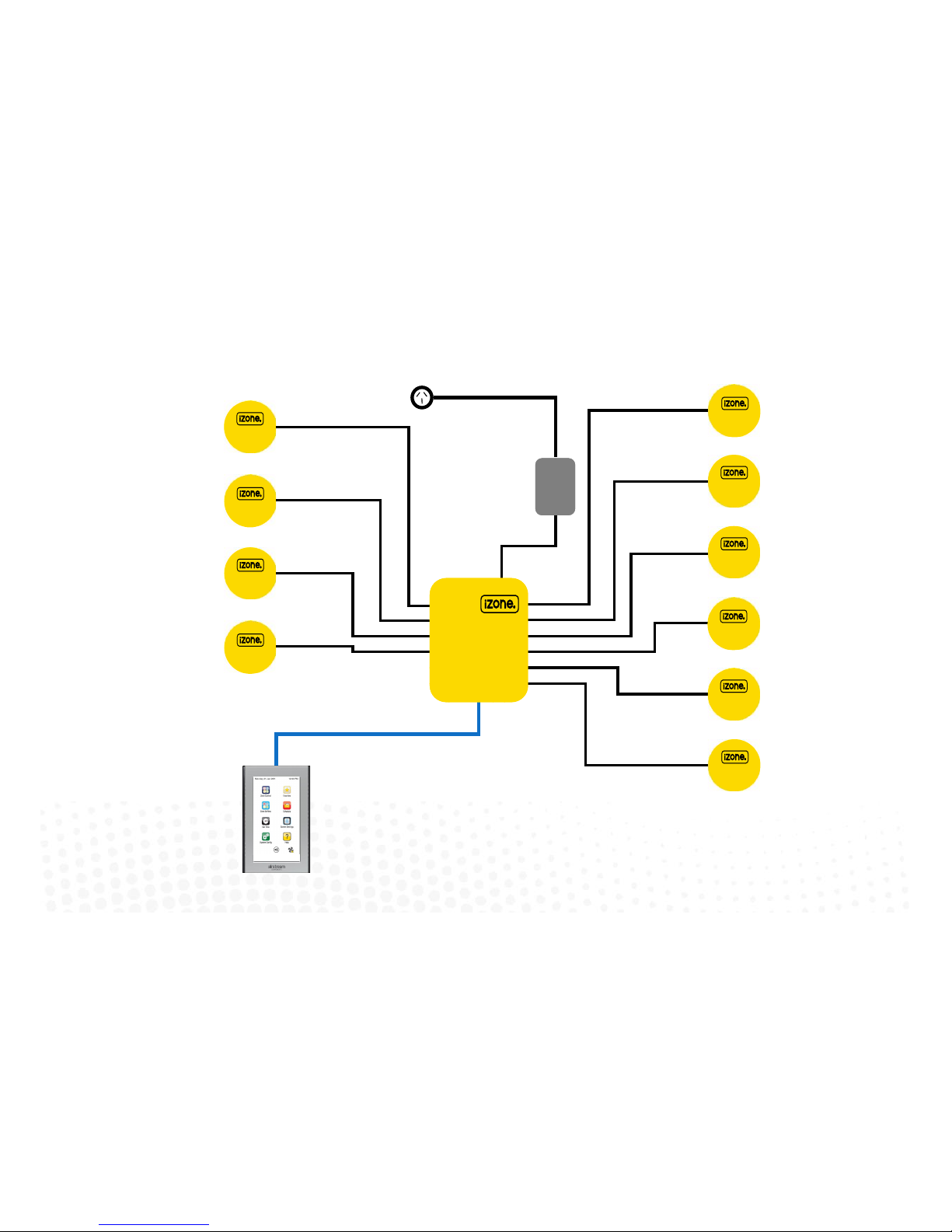
1.1 iZone 211 - Wiring layout for base system
iZone
CCTS
Zone 1
Zone 3
Zone 2
Zone 4
Zone 6
Zone 10
Zone 8
Zone 9
Zone 7
Zone 5
10 Zone system with 1 colour touch screen shown above
A maximum of 12 zones and 12 colour touch screens can be supported by
one iZone system (See Network Extension Module 1.3 for Details)
CZDA
CT24AC
CCPU
Central Processing Unit
5
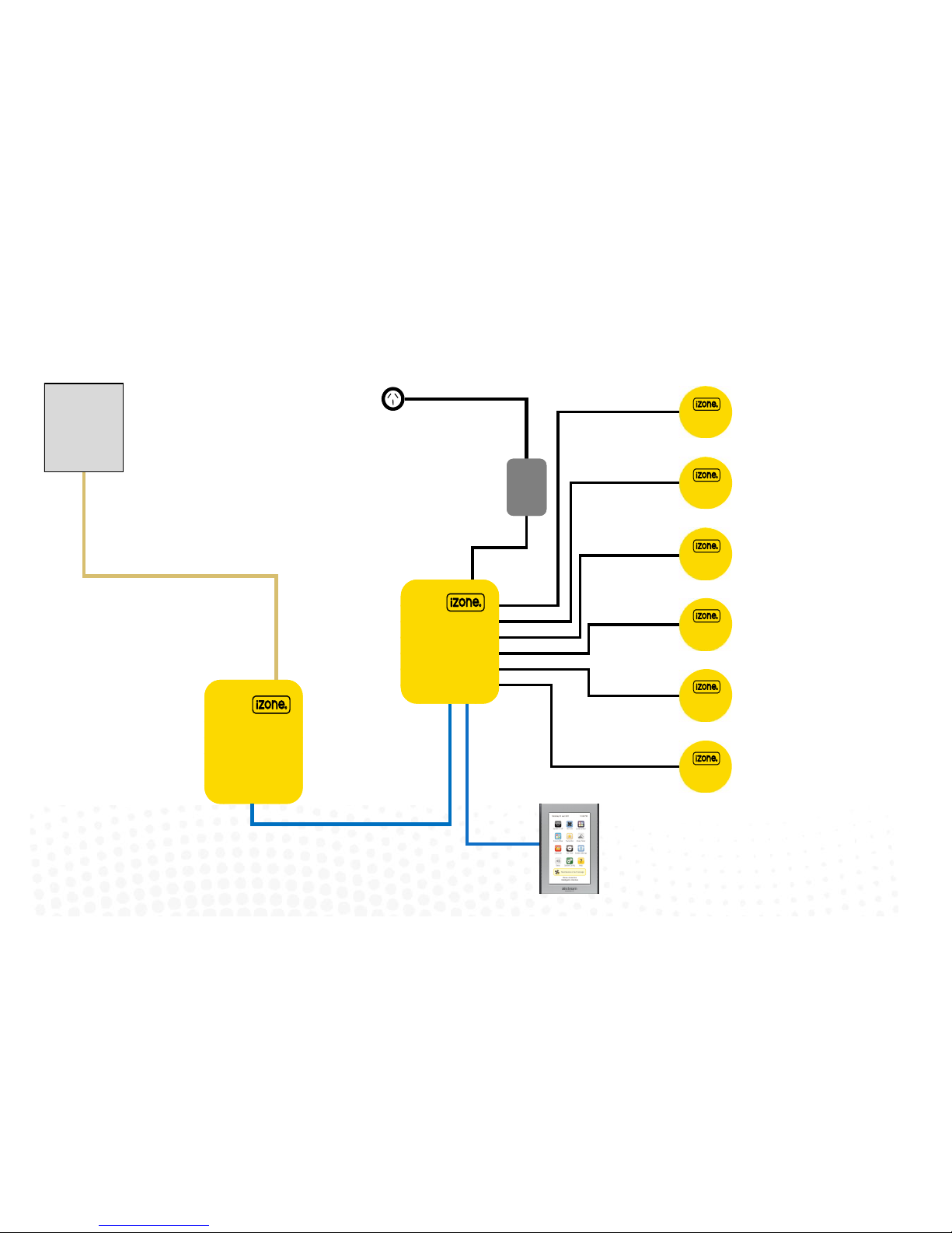
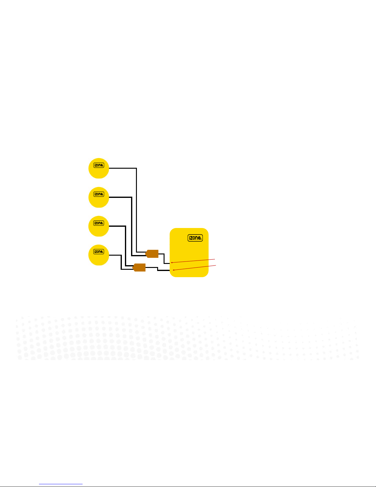
1.2 iZone 311 - Wiring layout for base system
CCPU
Central Processing Unit
CZDA
Zone 3
Zone 2
Zone 4
Zone 6
Zone 5
CT24AC
6 Zone system with 1 colour touch screen shown.
A maximum of 12 zones and 12 colour touch screens can be supported by one
iZone system (See Network Extension Module 1.3 for Details)
CACUM
AC Unit Module
Zone 1
AC Unit
AC unit control cable.
See table for locaon of connecon in
AC unit (1.7)
CCTS
Make sure you have the
correct model of CACUM for
the make of AC unit. See back
of CACUM for details

1.3 Optional equipment for temperature controlled zones
CCPU
Central Processing Unit
CDTS
Installed into the
supply air duct o
the fan coil unit
CCTS
CCTS (oponal)
Install addional
colour touch screens
in zones requiring
temperature control
CSM (oponal)
Install Sensor Module
to allow for Wired
temperature sensors
(CS) & Wireless
temperature sensors
(CRFS
CS (oponal)
Wired Temperature
Sensors (Max 12 per
system)
CRFS (oponal)
Wireless Temperature
Sensors (Max 12 per
system)
CSM
Sensor Module
CZCO
(oponal)
Wired Zone
Controllers
with
temperature
and occupancy
sensor (Max 12
per system)
Connect Sensor
module to any
network port in the
system (CCTS or
CNEM)
6
CNEM
Network Extension Module
CT24AC
CCTS
CNEM (oponal)
Install Network
Extension Module to
provide addional
network ports if
required
CR (oponal)
Wireless Repeaters
R
7
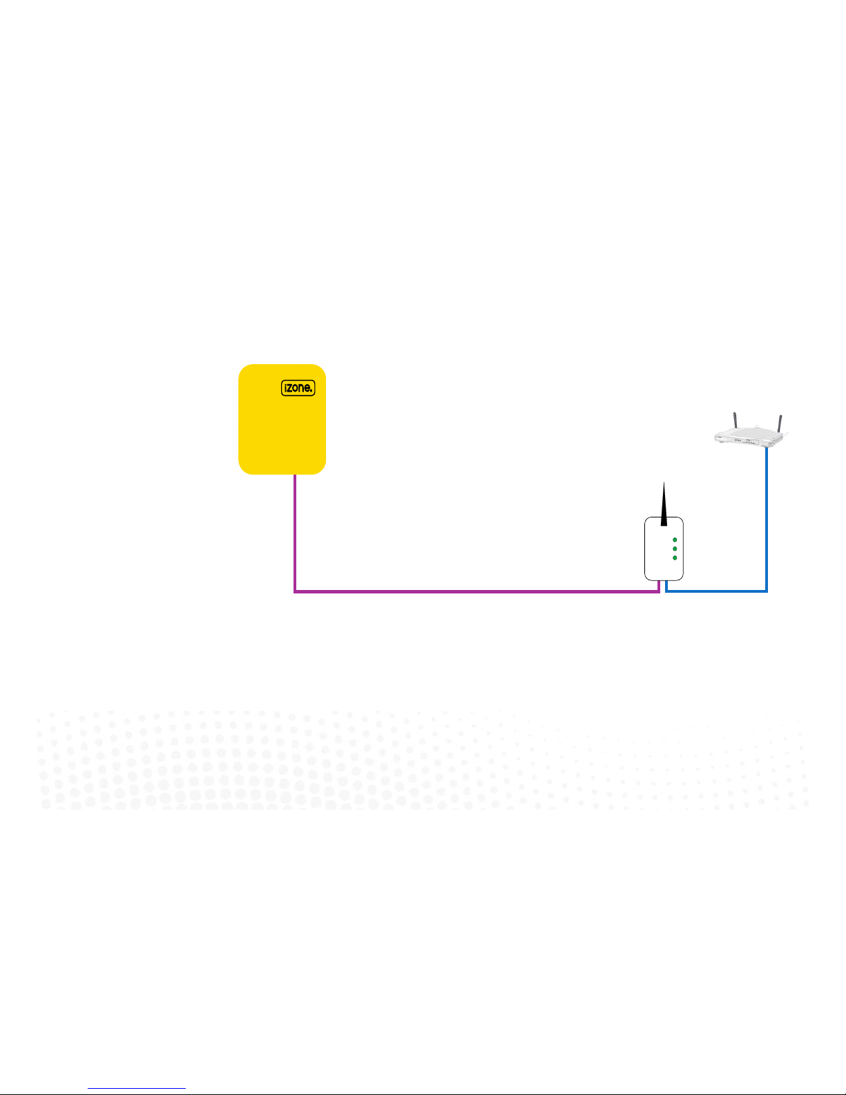
1.4 Optional equipment for wired WiFi Control of system
CCPU
Central Processing Unit
CB
Wired
Bridge
Customers
router or
modem
RJ45-12
This cable is specic for
connecng the CCPU and Wired
Bridge
B
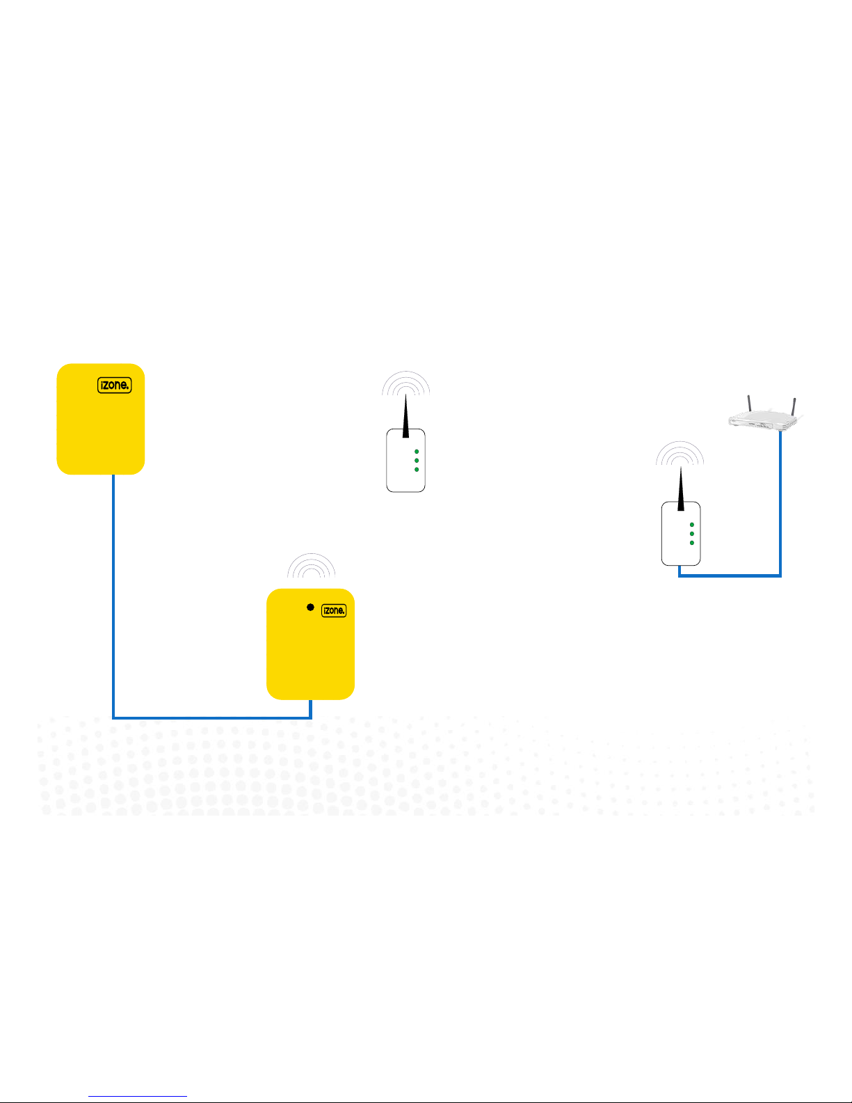
1.5 Optional equipment for wireless WiFi control
CCPU
Central Processing Unit
CSM
Install Sensor Module
to allow for wirless
communicaon with
Wireless Bridge (CB).
Only one CSM is
required per system.
CSM
Sensor Module
CB
Wireless
Bridge
Customers
router or
modem
8
B
CR (oponal)
Wireless Repeaters
R
9
1.6 iZone 311 - Optional equipment for isave addition
CCPU
Central Processing Unit
Note:
When the isave option is used the iZone system is limited to a maximum of
10 Zones
Return
Air Damper 1
Return
Air Damper 2
Outside Air
Air Damper 1
Outside Air
Air Damper 2
CDAK
CDAK
Use Zone 12 port on CCPU for Outside Air dampers
Use Zone 11 port on CCPU for Return Air dampers
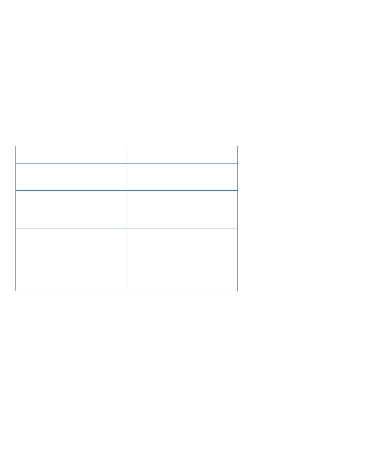
1.7 iZone 311 - Wiring connection to AC units
Unit Make Connection
Daikin Take the P1 / P2 control wire from the fan coil
unit and connect it to the AC Unit Control
Cable on the CACUM.
LG See detailed instructions on 1.8 page 11
Mitsubishi Electric Take the Remote Controller (A / B) control
wire from the fan coil unit and connect it to
the AC Unit Control Cable on the CACUM.
Panasonic Take the A / B control wire from the fan coil
unit and connect it to the AC Unit Control
Cable on the CACUM.
Temperzone See detailed instructions on 1.9 page 12
Toshiba Take the A / B control wire from the fan coil
unit and connect it to the AC Unit Control
Cable on the CACUM.
10
11
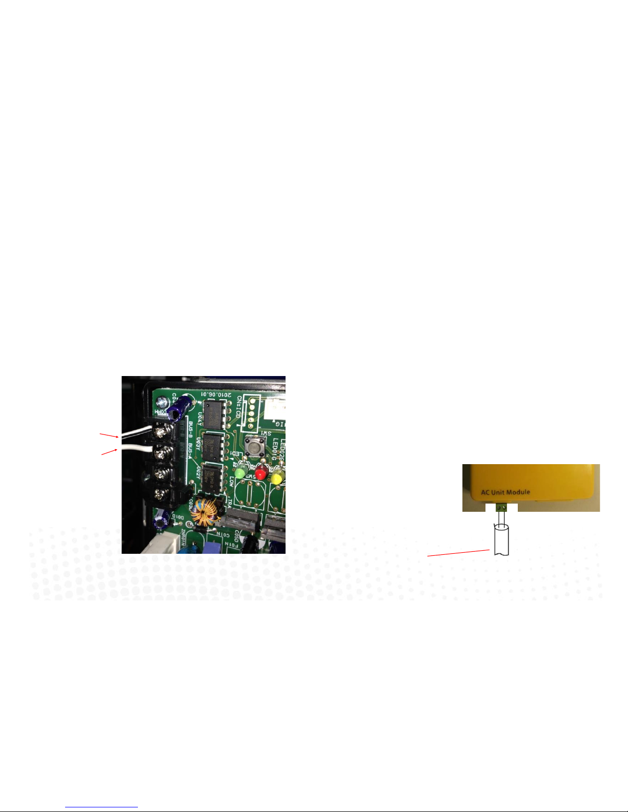
1.8 iZone 311 - Wiring connection to LG units
Unit Make Connection
LG
LG condensing unit must be supplied with an
optional PI485 Gateway (M) board in the
condensing unit.
1. Connect a shielded, 2 core, twisted pair control cable from the CACUM to the PI485
Gateway (M) board in the condensing unit. (This cable is supplied by the installer). Polarity
is critical see Fig (C) & (D) for correct connection.
Fig (C) - LG PI485 Gateway (M) board in condensing
unit
Shielded, 2 core,
twisted pair control
cable (not supplied)
Shielded, 2 core,
twisted pair control
cable (not supplied)
Fig (D) - iZone /
LG AC Unit Module
A
B
Correct polarity for
CACUM
A B
12
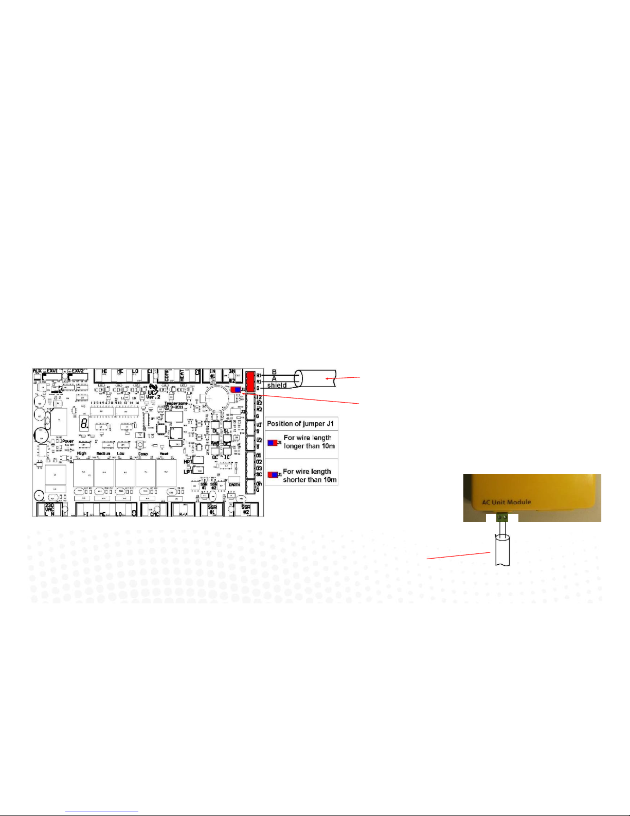
1.9 iZone 311 - Wiring connection to Temperzone units
Unit Make Connection
Temperzone 1. Connect a shielded, 2 core, twisted pair control cable from the CACUM to the UC7 board
in the condensing unit. (This cable is supplied by the installer). Polarity is critical see Fig A
& B for correct connection.
2. Adjust location of jumper J1 to suit the length of control cable installed.
3. Ensure the dip switches in the condensing unit are set correctly for the installed
compressor type (digital / fixed speed) and fan speed control. Refer to the Temperzone
service manual.
Fig (A) - Temperzone UC7 outdoor
Shielded, 2 core, twisted pair
control cable (not supplied)
Adjust jumper J1 to suit cable
length
Shielded, 2 core,
twisted pair control
cable (not supplied)
Correct polarity for
CACUM
A B
Fig (B) - iZone / Temperzone AC
Unit Module

13
1.10 General installation instructions
1. The CCPU and CACUM can be installed on top of the indoor fan coil unit.
2. The CSM should be installed on the ceiling in the centre of the house. If any wireless sensor (CRFS) or wireless bridge (CB) is not within
the range of the CSM then additional repeaters (CR) should be added to help relay the signal from the field device to the CSM.
3. Do not run the blue network cables alongside 240 Volt wiring.
4. When installing network cables down wall cavities or chasing network cables into walls, tape up and protect the RJ45 connector to avoid
damage to the connectors. Installation damage to cables is not covered under warranty.
5. Always install zones in consecutive ports starting at Zone 1. The back of the CCPU is marked with the zone port numbers.
6. Do not directly hardwire the CT24V into the AC unit’s power supply. This may void the warranty as it will require an electrician in the event
that a repair of the iZone power supply is required.
7. Connect Zone Damper Actuators (CZDA) to the zone ports using the RJ11 cables as shown.
8. Connect the Colour Touch Screens (CCTS) to the CAN ports using the RJ45 cables. If you are connecting more than 3 components
requiring CAN ports to the system you will need to connect a Network Extension Module (CNEM) to one of the CAN ports on the CCPU
using a short RJ45 cable. The CACUM will also support one CAN port.
9. If any zone is temperature controlled connect a Duct Temperature Sensor (CDTS) to the CDTS port. Install the sensor into the supply air
duct upstream of all dampers. Secure the sensor in place by using reinforced aluminium tape.
10. When installing temperature controlled zones ensure the CCTS or sensor for the associated zone is installed in a location that is
representative of the temperature in the room / zone . The sensor should be installed at approximately 1600mm above the floor and
should not be subject to draughts, direct sunlight or heat from equipment such as computers, TV screens etc. The supply air outlets to
this room must not blow conditioned air directly onto the sensors or touch screens, as a temperature sensor is located in the CCTS.
11. Connect the AC unit control cable to the CACUM. See table 1.7 For details. (This cable is not supplied by Airstream.)
12. The building must be fitted with a compatible WiFi modem. Contact Airstream for a list of approved and recommended modems.
13. If connecting the iZone system to a Home Automation system use an RS 232 or RS 484 serial connector.
14. Only connect the power supply to the CT24VAC port after all components have been connected.
14
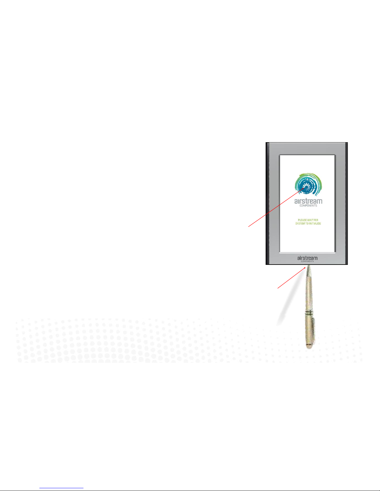
2.0 System initialisation
All new or modified systems must be initialised prior to system configuration.
To initialise the system press the button on the underside of any colour touch
screen. This button is recessed so you will need to use a pen to press the button.
The time to initialise the system will vary depending on the number of motors
connected.
The system will also initialise when power is restored after a power failure.
Airstream logo will spin while system is
inialising.
Using a pen, press the buon on the
underside of the screen.
15
3.0 System configuration
WARNING ! Only qualified iZone install ers should configure the i Zone System. Incorrect config ur ation could result in
damage to your air conditioning unit and system.
To configure your system click on the System Config icon on the home page.
Enter the system password “wamfud” and press the enter button. The enter button must always be touched to
save changes.
You will now be in the System Configuration area:
 Loading...