

Page 1

ZMOTION™ Detection Module
Development Kit
Quick Start Guide
QS007308-1210
Introduction
This quick start guide describes how to set up and use Zilog’s ZMOTION Detection Module Development Kit. The Kit can be used to demonstrate and evaluate the operation of the
ZMOTION Detection Module in both Hardware and Serial modes.
This quick start guide also provides the steps required for using Hardware mode. For additional information please refer to the ZMOTION Detection Module Development Kit User
Manual (UM0223).
Kit Contents
All hardware (except an external adjustable power supply), software and documentation
required to develop your motion detection application is included within the ZMOTION
Detection Module Development Kit.
Hardware
The ZMOTION Detection Module Development Kit includes the following hardware:
• ZMOTION Detection Module Base Board
• ZMOTION Detection Module
• RS-232 Serial Cable DB9-DB9
• 5 V DC Universal Power Supply
Documentation
The related technical documentation (on CD-ROM) includes:
• ZMOTION Detection Module Development Kit User Manual (UM0223)
• ZMOTION Detection Module Product Specification (PS0284)
• ZMOTION Detection Module Product Brief (PB0223)
Please refer to the Zilog website at www.zilog.com
mentation.
Copyright ©2011 Zilog®, Inc. All rights reserved.
www.zilog.com
to obtain the most up-to-date docu-
Page 2
ZMOTION™ Detection Module Development Kit
Quick Start Guide
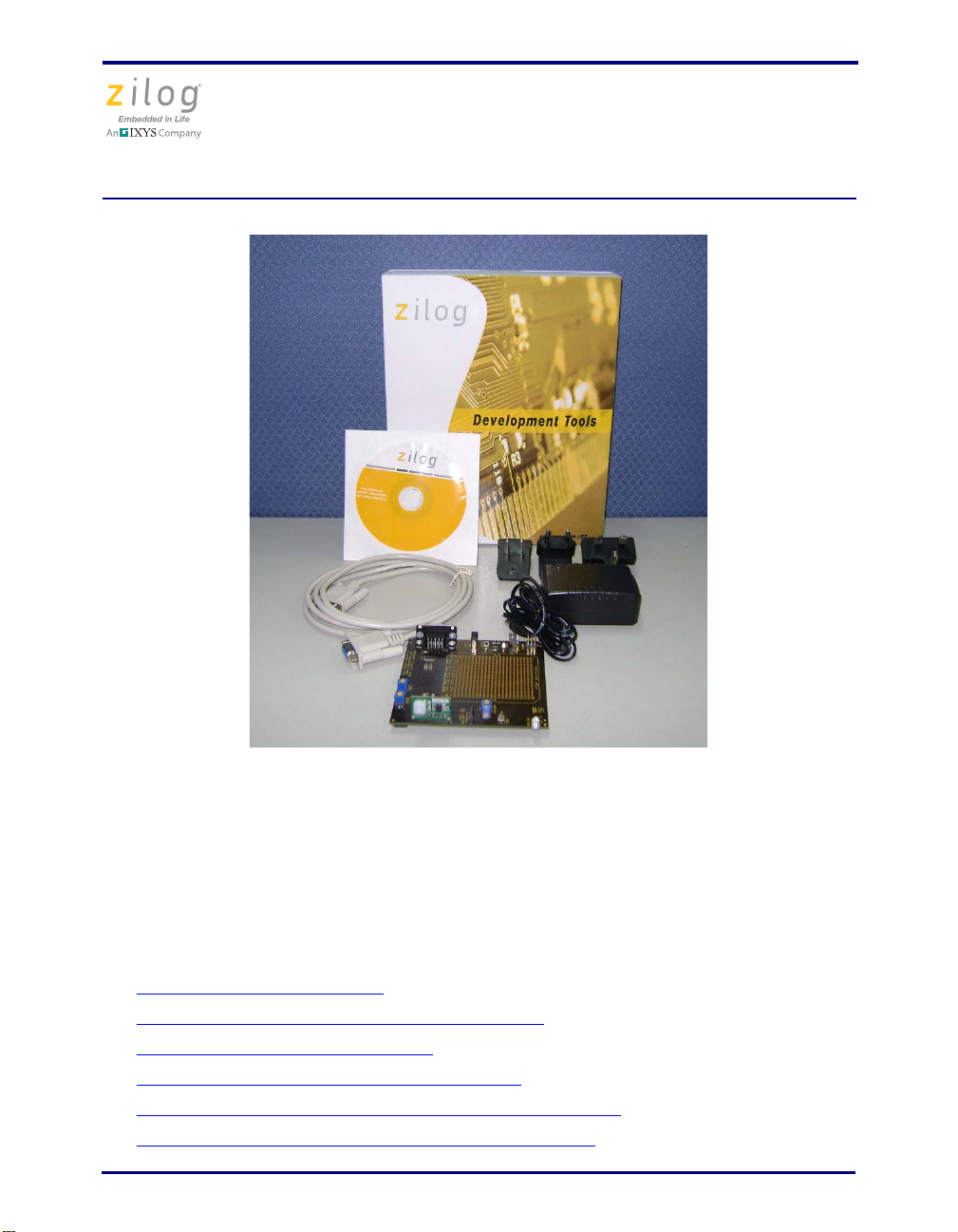
Figure 1. ZMOTION Detection Module Evaluation Kit Components
Setting up for Initial Operation
The simplest mode in which to use the module is Hardware Mode. In this mode, the sensitivity, ambient light level and LED “On” time are all adjusted using the controls on the
Base Board. There are a few simple steps in order to begin using the kit in Hardware
Mode; each of the following steps links to their respective descriptions on the pages that
follow.
• Step 1: Unpack the Hardware
• Step 2: Attach the ZMOTION Detection Module
• Step 3: Install the AC Plug Adapter
• Step 4: Configure Jumpers, Switches and Pots
• Step 5: Apply Power to the ZMOTION Detection Module
• Step 6: Demonstrate the ZMOTION Detection Module
QS007308-1210 Page 2 of 6
on page 3
on page 3
on page 4
on page 4
on page 4
on page 5
Page 3

ZMOTION™ Detection Module Development Kit
Quick Start Guide
Step 1: Unpack the Hardware
Remove the ZMOTION Base Board, ZMOTION Module and Power Supply from their
protective bags. ESD precautions must be used when handling the ZMOTION Base Board
and the ZMOTION Module.
Step 2: Attach the ZMOTION Detection Module
Insert the ZMOTION Detection Module into J4 of the Base Board. Ensure that pin 1 is
aligned correctly, as indicated by a square silkscreen on the J4 connector.
Figure 2. ZMOTION Detection Module
QS007308-1210 Page 3 of 6
Page 4

ZMOTION™ Detection Module Development Kit
Quick Start Guide
Step 3: Install the AC Plug Adapter
The universal power supply kit features four different plug adapters in one box and the
power supply by itself in another. The power supply ships with a slide-out plate that must
be removed to insert the location-specific plug adapter.
Follow the steps below to install the location specific adapter.
1. Remove the slide-out plate.
2. Select the appropriate AC plug adapter and insert it into the slot that remains after
removing the slide-out plate.
3. Slide the new plug adapter into the slot until it snaps into place.
You can also leave the adapter slot cover in place and plug in a standard computer equipment AC power cord (purchased separately) between the AC cord receptacle on the end of
the power supply and an electrical outlet.
Step 4: Configure Jumpers, Switches and Pots
Ensure that the base board is configured as indicated in Table 1.
Table 1. H/W Mode Demonstration Settings
Component Status
SW1 Hardware
J7 – PA1/ANA3 AMBIENT (ON on shunted)
J11 – STATE RUN (OFF or un-shunted)
R3 – SENS Set mid-way
R4 – DELAY Turned all the way to “-“
R6 – AMBIENT Turned all the way to “-“ or “Light”
Step 5: Apply Power to the ZMOTION Detection Module
Connect the power supply to the Base Board at P2, then to an electrical outlet. Ensure that
the green LED (D2) illuminates.
QS007308-1210 Page 4 of 6
Page 5

ZMOTION™ Detection Module Development Kit
Quick Start Guide
Step 6: Demonstrate the ZMOTION Detection Module
After no more than about 30 seconds, generate motion in front of the ZMOTION Detection Module and observe the blue LED D1, which should flash for about 2 seconds.
• Adjust R3 (Sense) to change motion sensitivity
• Adjust R4 (Delay) to change the duration in which the LED stays on
• Adjust R6 (Ambient) to change the amount of ambient light allowed to stop the LED
from turning on
For additional information please refer to the ZMOTION Detection Module Development
Kit User Manual (UM0223).
QS007308-1210 Page 5 of 6
Page 6

ZMOTION™ Detection Module Development Kit
Warning:
Quick Start Guide
DO NOT USE THIS PRODUCT IN LIFE SUPPORT SYSTEMS.
LIFE SUPPORT POLICY
ZILOG’S PRODUCTS ARE NOT AUTHORIZED FOR USE AS CRITICAL COMPONENTS IN LIFE SUPPORT DEVICES OR SYSTEMS WITHOUT THE EXPRESS
PRIOR WRITTEN APPROVAL OF THE PRESIDENT AND GENERAL COUNSEL OF
ZILOG CORPORATION.
As used herein
Life support devices or systems are devices which (a) are intended for surgical implant
into the body, or (b) support or sustain life and whose failure to perform when properly
used in accordance with instructions for use provided in the labeling can be reasonably
expected to result in a significant injury to the user. A critical component is any component in a life support device or system whose failure to perform can be reasonably
expected to cause the failure of the life support device or system or to affect its safety or
effectiveness.
Document Disclaimer
©2011 Zilog, Inc. All rights reserved. Information in this publication concerning the
devices, applications, or technology described is intended to suggest possible uses and
may be superseded. ZILOG, INC. DOES NOT ASSUME LIABILITY FOR OR PROVIDE A REPRESENTATION OF ACCURACY OF THE INFORMATION, DEVICES,
OR TECHNOLOGY DESCRIBED IN THIS DOCUMENT. ZILOG ALSO DOES NOT
ASSUME LIABILITY FOR INTELLECTUAL PROPERTY INFRINGEMENT
RELATED IN ANY MANNER TO USE OF INFORMATION, DEVICES, OR TECHNOLOGY DESCRIBED HEREIN OR OTHERWISE. The information contained within
this document has been verified according to the general principles of electrical and
mechanical engineering.
ZMOTION is a trademark or registered trademark of Zilog, Inc. All other product or service names are the property of their respective owners.
QS007308-1210 Page 6 of 6
 Loading...