

IXYS DSEK60-02AR, DSEK60-02A Datasheet
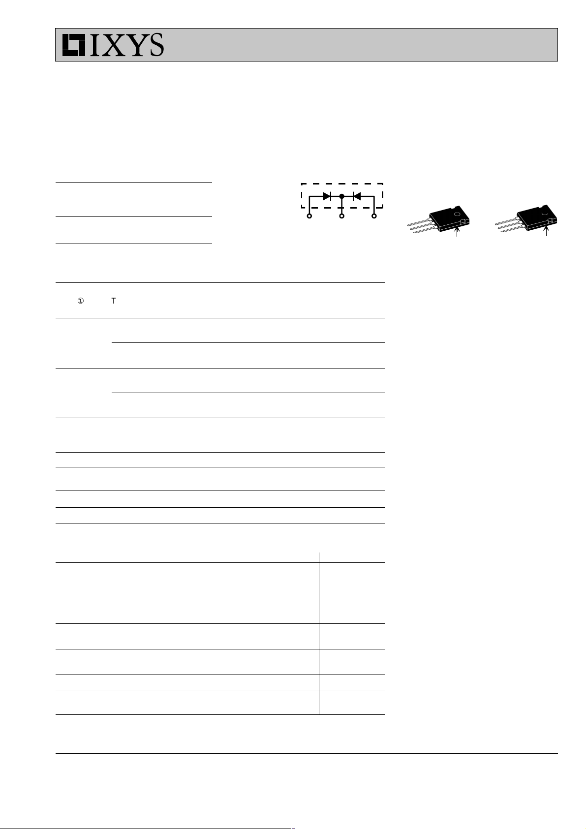
Common Cathode
Fast Recovery
Epitaxial Diode (FRED)
DSEK 60 I
FAVM
V
RRM
t
rr
= 2x 34 A
= 200 V
= 35 ns
V
RSM
V
RRM
Type
TO-247 AD ISOPLUS 247
Version A Version AR
V V
200 200 DSEK 60-02A
A C A
A
200 200 DSEK 60-02AR
A = Anode, C = Cathode
Symbol Test Conditions Maximum Ratings per leg
I
FRMS
I
ÿÿ
① TC = 115°C; rectangular, d = 0.5 34 A
FAVM
I
FRM
I
FSM
TVJ = T
VJM
tP < 10 ms; rep. rating, pulse width limited by T
VJM
50 A
375 A
TVJ = 45°C; t = 10 ms (50 Hz), sine 325 A
t = 8.3 ms(60 Hz), sine 350 A
TVJ = 150°C; t = 10 ms (50 Hz), sine 290 A
t = 8.3 ms(60 Hz), sine 310 A
I2t TVJ = 45°C t = 10 ms (50 Hz), sine 530 A2s
Features
●
●
●
●
●
●
●
●
t = 8.3 ms(60 Hz), sine 510 A2s
TVJ = 150°C; t = 10 ms (50 Hz), sine 420 A2s
t = 8.3 ms(60 Hz), sine 400 A2s
T
VJ
T
VJM
T
stg
P
tot
TC = 25°C 125 W
-40...+150 °C
150 °C
-40...+150 °C
Md * Mounting torque 0.8...1.2 Nm
F
C
V
** 50/60 Hz, RMS, t = 1 minute, leads-to-tab 2500 V~
ISOL
mounting force with clip 20...120 N
Weight 6g
* Verson A only; ** Version AR only
Applications
●
●
●
Advantages
●
●
Symbol Test Conditions Characteristic Values per leg
typ. max.
I
R
V
F
V
T0
r
T
R
thJC
R
thCH
t
rr
I
RM
TVJ = 25°CVR= V
TVJ = 25°CVR= 0.8 • V
RRM
TVJ = 125°CVR= 0.8 • V
RRM
RRM
200 mA
50 mA
5mA
IF = 30 A; TVJ= 150°C 0.85 V
TVJ=25°C 1.10 V
For power-loss calculations only 0.72 V
TVJ = T
VJM
4.2 mW
1 K/W
0.25 K/W
IF = 1 A; -di/dt = 100 A/ms; VR = 30 V; TVJ = 25°C3550ns
VR = 100 V; IF = 30 A; -diF/dt = 100 A/ms45A
L £ 0.05 mH; TVJ = 25°C
●
●
●
C
A
C (TAB)
A
C
A
back surface *
* Patent pending
International standard package
JEDEC TO-247 AD
Planar passivated chips
Very short recovery time
Extremely low switching losses
Low IRM-values
Soft recovery behavior
Epoxy meets UL 94V-0
Version AR isolated and
UL registered E153432
Rectifiers in switch mode power
supplies (SMPS)
Uninterruptible power supplies (UPS)
Ultrasonic cleaners and welders
High reliability circuit operation
Low voltage peaks for reduced
protection circuits
Low noise switching
Low losses
Operating at lower temperature or
space saving by reduced cooling
TM
Isolated
① I
rating includes reverse blocking losses at T
FAVM
Data according to IEC 60747 refer to a single diode unless otherwise stated.
IXYS reserves the right to change limits, test conditions and dimensions
, VR = 0.8 V
VJM
, duty cycle d = 0.5
RRM
© 2000 IXYS All rights reserved
036
1 - 2

DSEK 60, 200V
120
A
100
I
F
80
60
TVJ=150°C
40
TVJ=100°C
TVJ= 25°C
20
0
0.0 0.4 0.8 1.2
V
F
Fig. 1 Forward current IF versus V
1.6
1.4
K
f
1.2
1.0
0.8
0.6
I
RM
Q
r
0.4
0 40 80 120 160
°C
T
VJ
Fig. 4 Dynamic parameters Qr, I
versus T
VJ
Q
0.8
µC
r
0.6
TVJ= 100°C
VR = 100V
I
RM
30
TVJ= 100°C
A
VR = 100V
25
20
IF= 15A
IF= 35A
IF= 70A
IF= 15A
0.4
IF= 35A
15
IF= 70A
10
0.2
5
V
10 100 1000
A/ms
-diF/dt
0.0
F
Fig. 2 Typ. reverse recovery charge Q
versus -diF/dt
70
ns
60
t
rr
50
TVJ= 100°C
VR = 100V
0
200 600 10000 400 800
-di
Fig. 3 Typ. peak reverse current I
r
V
FR
versus -diF/dt
6
V
t
5
TVJ= 100°C
fr
IF = 35A
4
F
A/ms
/dt
RM
1.8
µs
1.5
V
FR
t
fr
1.2
40
3
0.9
30
IF= 15A
20
IF= 35A
IF= 70A
10
0
200 600 10000 400 800
RM
Fig. 5 Typ. recovery time t
versus -diF/dt
-di
A/ms
/dt
F
rr
2
1
0
0 200 400 600 800
A/ms
diF/dt
Fig. 6 Typ. peak forward voltage
VFR and t
versus diF/dt
fr
0.6
0.3
0.0
1.2
K/W
1.0
0.8
Z
thJC
0.6
0.4
0.2
0.0
0.001 0.01 0.1 1 10
t
Fig. 7 Transient thermal impedance junction to case
© 2000 IXYS All rights reserved
DSEK 60-02
s
Dimensions
Dim. Millimeter Inches
Min. Max. Min. Max.
A 19.81 20.32 0.780 0.800
B 20.80 21.46 0.819 0.845
C 15.75 16.26 0.610 0.640
D* 3.55 3.65 0.140 0.144
E 4.32 5.49 0.170 0.216
F 5.4 6.2 0.212 0.244
G 1.65 2.13 0.065 0.084
H - 4.5 - 0.177
J 1.0 1.4 0.040 0.055
K 10.8 11.0 0.426 0.433
L 4.7 5.3 0.185 0.209
M 0.4 0.8 0.016 0.031
N 2.2 2.54 0.087 0.102
* ISOPLUS 247
TM
without hole
2 - 2
 Loading...