

Page 1

USB-to-CAN
Plugin
USER MANUAL
4.01.0288.20000 2.0 en-US ENGLISH
V2
Page 2

Important User Information
Disclaimer
The information in this document is for informational purposes only. Please inform HMS Industrial Networks of any
inaccuracies or omissions found in this document. HMS Industrial Networks disclaims any responsibility or liability
for any errors that may appear in this document.
HMS Industrial Networks reserves the right to modify its products in line with its policy of continuous product
development. The information in this document shall therefore not be construed as a commitment on the part of
HMS Industrial Networks and is subject to change without notice. HMS Industrial Networks makes no commitment
to update or keep current the information in this document.
The data, examples and illustrations found in this document are included for illustrative purposes and are only
intended to help improve understanding of the functionality and handling of the product. In view of the wide range
of possible applications of the product, and because of the many variables and requirements associated with any
particular implementation, HMS Industrial Networks cannot assume responsibility or liability for actual use based on
the data, examples or illustrations included in this document nor for any damages incurred during installation of the
product. Those responsible for the use of the product must acquire sufficient knowledge in order to ensure that the
product is used correctly in their specific application and that the application meets all performance and safety
requirements including any applicable laws, regulations, codes and standards. Further, HMS Industrial Networks will
under no circumstances assume liability or responsibility for any problems that may arise as a result from the use of
undocumented features or functional side effects found outside the documented scope of the product. The effects
caused by any direct or indirect use of such aspects of the product are undefined and may include e.g. compatibility
issues and stability issues.
USB-to-CANV2User Manual
4.01.0288.20000 2.0 en-US
Page 3

Table of Contents
Page
1 User Guide ........................................................................................................................... 3
1.1 Target Audience............................ ................................................................................... 3
1.2 Related Documents ......................... ............................ ............... ............. ............... .......... 3
1.3 Document History ........ ............... ............. ............... ............................ ............................ .3
1.4 Trademark Information ............ ............... ............. ............... ............. ............... ..................3
1.5 Conventions.............................................................................................................. ...... 4
2 Safety Instructions .............................................................................................................. 5
2.1 Information on EMC .........................................................................................................5
2.2 General Safety Instructions ................................................................................................ 5
2.3 Intended Use.. ............................ ............... ............. ............... ............. ............... ............. .5
3 Scope of Delivery ................................................................................................................ 5
4 Product Description ............................................................................................................ 6
5 Installation........................................................................................................................... 7
5.1 Installing the Software ...................................................................................................... 7
5.2 Installing the Hardware ................................................................................. ....................7
6 Connectors........................................................................................................................... 9
6.1 USB Connector ............. ............................ ............. .. ............. ............................ ............... 9
6.2 Fieldbus Connectors ..... ............... ............. ............... ............................ ............................ .9
6.2.1 Connecting the CAN Fieldbus... ... .... ... ... . ... ... .... ... ... . ... ... . ... ... .... ... ... . ... ... . ... ... . ... ... ... . 10
6.2.2 Connecting the LIN Fieldbus .. ... ... . ... ... ... . ... ... . ... ... .... ... ... . ... ... . ... ... .... ... ... . ... ... . ... ... ... 10
7 LEDs.................................................................................................................................... 11
7.1 USB LED .... ............................ ............. .. ............. ............... ............. ............................... 11
7.2 CAN LED .......... ............................ ................................................................................. 12
7.3 CAN1 LS LED....................................................................................................... ........... 12
7.4 LIN LED ............ ............. ............................................................................................... 12
8 Additional Components .................................................................................................... 13
8.1 CAN Bus Termination......... ............. ............... ............. ............... ............. ............... ......... 13
USB-to-CANV2User Manual
4.01.0288.20000 2.0 en-US
Page 4

9 Technical Data ................................................................................................................... 14
10 Troubleshooting ................................................................................................................ 15
11 Cleaning ............................................................................................................................. 16
12 Support/Return Hardware................................................................................................ 16
12.1 Support ..................................................................................................... ............... .... 16
12.2 Return Hardware ........................................................................................................... 16
13 Disposal.............................................................................................................................. 16
A Measurements .................................................................................................................. 17
B Regulatory Compliance..................................................................................................... 18
B.1 EMC Compliance (CE) .......... ............................ ............................................................... 18
B.2 FCC Compliance Statement........... ............. ............... ............................ ........................... 18
B.3 Disposal and recycling............................................................................... ............. ......... 19
USB-to-CANV2User Manual
4.01.0288.20000 2.0 en-US
Page 5

User Guide 3 (20)
1 User Guide
Please read the manual carefully. Make sure you fully understand the manual before using the
product.
1.1 Target Audience
This manual addresses trained personnel who are familiar with CAN, LIN and the applicable
standards. Only ESD trained staff is authorized to install the interface. The contents of the
manual must be made available to any person authorized to use or operate the product.
1.2 Related Documents
Document
Installation Guide VCI Driver
1.3 Document History
Author
HMS
Version
2.0
Date
July 2020 Revised and edited in new design
1.4 Trademark Information
Ixxat®is a registered trademark of HMS Industrial Networks AB. All other trademarks mentioned
in this document are the property of their respective holders.
Description
USB-to-CANV2User Manual
4.01.0288.20000 2.0 en-US
Page 6
User Guide 4 (20)
1.5 Conventions
Instructions and results are structured as follows:
► instruction 1
► instruction 2
→ result 1
→ result 2
Lists are structured as follows:
• item 1
• item 2
Bold typeface indicates interactive parts such as connectors and switches on the hardware, or
menus and buttons in a graphical user interface.
This font is used to indicate program code and other
kinds of data input/output such as configuration scripts.
This is a cross-reference within this document: Conventions, p. 4
This is an external link (URL): www.hms-networks.com
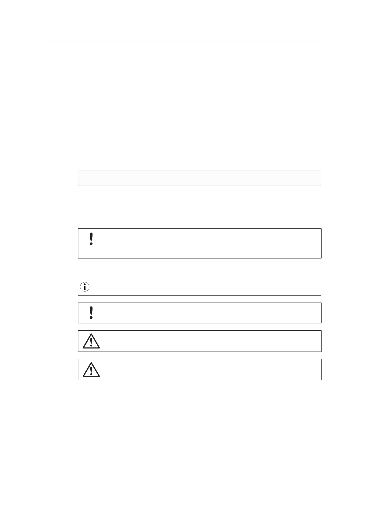
Safety advice is structured as follows:
Cause of the hazard!
Consequences of not taking remediate action.
How to avoid the hazard.
Safety signs and signalwords are used dependent on the level of the hazard.
This is additional information which may facilitate installation and/or operation.
This instruction must be followed to avoid a risk of reduced functionality and/or damage
to the equipment, or to avoid a network security risk.
Caution
This instruction must be followed to avoid a risk of personal injury.
WARNING
This instruction must be followed to avoid a risk of death or serious injury.
USB-to-CANV2User Manual
4.01.0288.20000 2.0 en-US
Page 7

Safety Instructions 5 (20)
2 Safety Instructions
2.1 Information on EMC
Risk of interference to radio and television if used in office or home environment! The
product is a class B device.
Use exclusively included accessories or HMS accessories that are intended for use with
the device. Use exclusively shielded cables.
Make sure that the shield of the interface is connected with the device plug and the plug
on the other side.
2.2 General Safety Instructions
► Protect product from moisture and humidity.
► Protect product from too high or too low temperature (see Technical Data, p. 14).
► Protect product from fire.
► Do not paint the product.
► Do not modify or disassemble the product. Service must be carried out by HMS Industrial
Networks.
► Store products in dry and dust-free place.
2.3 Intended Use
The interface is used to connect computer systems to CAN and LIN networks and is intended for
installation in computer systems with closed housing.
3 Scope of Delivery
Included in the scope of delivery:
• USB-to-CAN
• CD with driver, programming examples, CAN bus monitor and software design guide
• Installation Guide VCI Driver
• User Manual USB-to-CAN
The following equipment can be ordered separately:
• CAN bus termination
V2
Plugin interface
V2
Plugin
USB-to-CANV2User Manual
4.01.0288.20000 2.0 en-US
Page 8

Product Description 6 (20)
4 Product Description
The USB-to-CANV2Plugin is an active USB interface which enables the user to monitor and
control up to two CAN high-speed channels, one CAN low-speed channel, and a LIN channel,
depending on the variant.
Common Features
• USB 2.0 Hi-Speed (480 MBit/s)
• CAN high-speed channels according to ISO 11898-2: 2016
• connection using single row female header (field bus and USB)
Variant Dependent Features
Order number
1.01.0288.11003
1.01.0288.12003
1.01.0288.22003
1.01.0288.22043
Features
1 x CAN high-speed
1 x CAN high-speed channel, galvanic bus isolation
2 x CAN high-speed channels, galvanic bus isolation (both CAN channels on the
same potential)
2 x CAN high-speed channels, CAN 1 can be switched between high- and low-speed
(ISO 11898-3) via software
1 x LIN interface V1.3 and V2.0/2.1, Master/Slave mode and LIN frame format
switchable via software
galvanic bus isolation (both CAN channels on the same potential)
USB-to-CAN
V2
User Manual
4.01.0288.20000 2.0 en-US
Page 9

Installation 7 (20)
5 Installation
5.1 Installing the Software
For the operation of the interface a driver is needed.
Windows
► Install the VCI driver (see Installation Guide VCI Driver).
Linux and Real-Time Operating Systems
► Observe information about supported operating systems and interfaces on www.ixxat.com.
5.2 Installing the Hardware
Risk of ESD damages caused by improper handling!
Use ESD protective measures to avoid equipment damage.
Damage of the equipment because of reverse polarity or wrong type of power supply!
Make sure that the power supply is correctly connected and of the recommend type.
Insufficient power supply!
Connect the interface directly to the computer or to self-powered hubs to ensure
sufficient power supply.
The USB-to-CANV2Plugin can be mounted in two ways: with LEDs on the bottom side or with
LEDs on the top side. Note the different heights of the mounting options.
Option 1
LEDs are on the bottom side and not optimally visible when mounted.
Option 2
LEDs are on the top side and visible when mounted.
USB-to-CANV2User Manual
4.01.0288.20000 2.0 en-US
Page 10

Installation 8 (20)
► Make sure that the driver is installed.
► Turn off the computer.
► Pull the power cord.
► Open the computer case according to instructions of the computer manufacturer.
► Plug the USB-to-CAN
Fig. 1 Connectors
1
Channel 2, pin 1
2
Channel 1, pin 1
3 USB connector, pin 1
V2
Plugin in the suitable slot on the computer main board.
► Use the mounting holes on the USB-to-CANV2Plugin and fix the plugin with screws.
► Use a washer on both sides of the interface board.
Fig. 2 Mounting holes
► Close the computer case.
→ Hardware installation is complete.
Recommended Fastening Elements
Mounting hole diameter in mm
Max. screw diameter in mm
Recommended fastening element
2.7 3.2
5.0 7.0
M2.5 x 5 M3 x6
USB-to-CAN
V2
User Manual
4.01.0288.20000 2.0 en-US
Page 11

Connectors
6 Connectors
Fig. 3 Connectors
1
Channel 2, pin 1
2
Channel 1, pin 1
3 USB connector, pin 1
6.1 USB Connector
9 (20)
Malfunction caused by extension cable!
According to the USB specification connect the interface directly or via an active USB hub
to the computer. Do not use an extension cable.
The shield of the USB cable (Pin 5) is connected to ground (GND) using a 100 nF capacitor. The
shield of the CAN connector is also connected to the ground of the USB plug.
Pin Allocation
1
Red: +5 V/voltage +/VCC
2
White: D-/data-/USB-
3
Green: D+/data+/USB+
4
Black: GND/voltage-/ground
5
Black: S-GND/over current/shielding
6.2 Fieldbus Connectors
For not galvanic isolated variants field bus ground (CAN GND) and USB ground (GND) have the
same potential.
For galvanic isolated variants field bus ground (CAN GND) and USB ground (GND) are separated.
Note that the filed busses CAN 1, CAN 2, LIN have no galvanic isolation among each other.
The pinning of the single row female headers for the field bus connections depends on the
variant of the USB-to-CAN
USB-to-CANV2User Manual
For best noise immunity connect the shields of the CAN cables directly to the device ground.
V2
Plugin.
4.01.0288.20000 2.0 en-US
Page 12

Connectors
Pin Allocation Channel 1
USB-to-CANV2Plugin Variant
Pin No.
1
2
3 CAN GND
4
5
Pin Allocation Channel 2
Pin No. Signal
1
2
3 CAN GND
4 LIN
5
Signal
CAN high HS
CAN low HS
CAN high LS
CAN low LS
CAN high HS
CAN low HS
LIN VBat (18 V
max.)
11003 12003 22003 22043
x x x x
x x x x
x x x x
— — —
— — —
USB-to-CANV2Plugin Variant
11003 12003 22003 22043
— —
— —
— —
— — —
— — —
6.2.1 Connecting the CAN Fieldbus
10 (20)
x
x
x x
x x
x x
x
x
► If necessary install a bus termination (see CAN Bus Termination, p. 13).
► Observe pin allocation.
► Connect the CAN fieldbus connector to the CAN fieldbus.
► Start the CAN bus monitor on the computer.
► In the CAN bus monitor adjust USB-to-CAN
characteristics.
► Start the CAN bus monitor communication.
→ Received CAN messages are shown in the receive window of the CAN bus monitor.
→ CAN LED is green flashing with each CAN message.
6.2.2 Connecting the LIN Fieldbus
LIN functionality is exclusively available on the variant 1.01.0288.22043.
Power consumption is limited by a 1 kΩ resistor.
The LIN interface can receive and transmit LIN frames according to LIN specification V1.3 and
V2.0/2.1. The LIN interface can be configured as LIN master.
A 1 kΩ pull-up resistor is automatically activated in LIN Master mode and automatically
deactivated in LIN Slave mode. External pull-up resistors are not necessary.
V2
Plugin properties according to the fieldbus
► To use the LIN interface connect a voltage of 12 V DC (voltage range 8 to 18 V DC) to pin
VBAT.
To ensure successful transmission of LIN messages:
► Connect external voltage before LIN messages are transmitted.
► Make sure, that the external voltage is not switched off and on during operating in LIN
mode.
USB-to-CANV2User Manual
4.01.0288.20000 2.0 en-US
Page 13

LEDs
7 LEDs
The implemented LEDs vary dependent on the variant of the USB-to-CANV2Plugin.
Fig. 4 Connectors and LEDs
1 LED 1
2 LED 2
3 LED 3
4 LED 4
5 LED 5
6
Channel 2, pin 1
7
Channel 1, pin 1
8 USB connector, pin 1
11 (20)
Available LEDs of Different Variants
LED
1 USB
2 CAN 1 LS
3 CAN 1
4 CAN 2
5 LIN
Signal
7.1 USB LED
Reflects the status of the USB communication.
LED state
Off
Green
Red flashing State changes between power saving
USB-to-CANV2Plugin Variant
11003 12003 22003 22043
x x x x
— — —
x x x x
— —
— — —
Description
No communication
Communication possible Device is ready for use.
and active
Comments
Device not initialized, check power supply.
Device not connected to USB port.
Changing power state.
x x
x
x
USB-to-CAN
V2
User Manual
4.01.0288.20000 2.0 en-US
Page 14

LEDs
7.2 CAN LED
Reflects the status of CAN communication (CAN 1 and CAN 2).
12 (20)
LED state
Off
Green flashing
Red flashing Controller in error state Controller is in state error warning or in state error
Red Bus off Controller is in state bus off, no communication
7.3 CAN1 LS LED
CAN low-speed functionality according to ISO 11898-3 is exclusively available on variant 1.01.0288.22043.
LED state
Off CAN high-speed transceiver active CAN high-speed interface is activated.
Orange (red and green) CAN low-speed (fault tolerant)
7.4 LIN LED
Description
No communication No communication
Communication present
Description
transceiver active
Comments
Device not connected to CAN.
LED is triggered with each message.
passive, communication is possible.
possible.
Comments
CAN low-speed interface is activated.
LIN functionality is exclusively available on variant 1.01.0288.22043.
LED state
Off
Green flashing
Red flashing Communication with errors On transmission or reception of a LIN message an
Description
No communication
Communication present
Comments
No communication on LIN bus or device not
connected to LIN bus.
LED is triggered with each message.
error was detected.
USB-to-CAN
V2
User Manual
4.01.0288.20000 2.0 en-US
Page 15

Additional Components 13 (20)
8 Additional Components
8.1 CAN Bus Termination
There is no bus termination resistor for the CAN bus integrated in the interface. HMS Industrial
Networks offers a bus termination resistor as a feed through connector.
Fig. 5 CAN bus termination resistor
► For ordering information see www.ixxat.com.
USB-to-CANV2User Manual
4.01.0288.20000 2.0 en-US
Page 16

Technical Data 14 (20)
9 Technical Data
PC bus interface
Field bus connector Single row female header; 2,54 pitch
USB conncetion
Microcontroller/RAM/Flash 32 Bit RAM/136 kByte/512 kByte
Dimensions 67.5 x 40 x 9.2mm
Weight
Power supply
Galvanic isolation 1 kV
Operating temperature
Storage temperature
Relative humidity 10 to 95 %, non condensing
Housing material ABS plastic
Protection class
USB 2.0, Hi-Speed (480 MBit/s)
Single row female header; 2,54 pitch
14 g
Via USB, 5 V DC/300 mA
-40 to +85 °C
-40 to +85 °C
None
CAN High-Speed, ISO 11898–2: 2016
CAN bitrates
CAN transceiver TI SN65HVD251D
CAN bus termination
10 kbit/s to 1 Mbit/s
None
CAN Low-Speed, ISO 11898–3
CAN bitrates
CAN transceiver NXP TJA1055T
CAN bus termination RTH=RTL=4,7 kΩ
10 kbit/s to 125 kbit/s
LIN
LIN bitrates
LIN transceiver TJA1020
LIN VBAT
LIN
Max. 20 kbit/s
8 to 18 V DC, 12 V DC typical
USB-to-CAN
V2
User Manual
4.01.0288.20000 2.0 en-US
Page 17

Troubleshooting 15 (20)
10 Troubleshooting
USB LED is off after installation.
No communication
USB LED is red.
No appropriate USB driver is installed.
Device is not working.
Adapter cable is not according to specification.
► Make sure that the device is correctly connected to the USB port.
► Check the power supply.
► Make sure that device and driver are correctly initialized.
► Check if the correct VCI driver version is installed.
► Use an adapter cable according to the specification.
Extension cable is used.
Device is not initialized.
► Remove the extension cable.
► According to the USB specification connect the interface directly
or via an active USB hub to the computer.
► Initialize the device with the CAN bus monitor (see Fieldbus
Connectors, p. 9).
USB-to-CAN
V2
User Manual
4.01.0288.20000 2.0 en-US
Page 18

Cleaning 16 (20)
11 Cleaning
► Disconnect the device from power supply.
► Remove dirt with a soft, chemical untreated, dry cloth.
12 Support/Return Hardware
12.1 Support
► For problems or support with the product request support at www.ixxat.com/support.
► If required use support phone contacts on www.ixxat.com.
12.2 Return Hardware
► Fill in the form for warranty claims and repair on www.ixxat.com/support/product-returns.
► Print out the Product Return Number (PRN resp. RMA).
► Pack product in a physically- and ESD-safe way, use original packaging if possible.
► Enclose PRN number.
► Observe further notes on www.ixxat.com.
► Return hardware.
13 Disposal
► Dispose of product according to national laws and regulations.
► Observe further notes about disposal of products on www.ixxat.com.
USB-to-CANV2User Manual
4.01.0288.20000 2.0 en-US
Page 19

Appendix A: Measurements 17 (20)
A Measurements
All measurements are in mm.
USB-to-CANV2User Manual
4.01.0288.20000 2.0 en-US
Page 20

Appendix B: Regulatory Compliance 18 (20)
B Regulatory Compliance
B.1 EMC Compliance (CE)
The product is in compliance with the Electromagnetic Compatibility Directive. More information
and the Declaration of Conformity is found at www.ixxat.com.
B.2 FCC Compliance Statement
This device complies with Part 15 of the FCC Rules. Operation is subject to the following two
conditions:
• This device may not cause harmful interference.
• This device must accept any interference received, including interference that may cause
undesired operation.
Product name USB-to-CANV2Plugin
Responsible party HMS Industrial Networks Inc
Address 35 E. Wacker Dr, Suite 1700
Phone
Any changes or modifications not expressly approved by HMS Industrial Networks could
void the user's authority to operate the equipment.
This equipment has been tested and found to comply with the limits for a Class B digital
device, pursuant to Part 15 of the FCC rules. These limits are designed to provide
reasonable protection against harmful interference in a residential installation. This
equipment generates, uses and can radiate radio frequency energy and, if not installed
and used in accordance with the instructions, may cause harmful interference to radio
communications. However, there is no guarantee that interference will not occur in a
particular installation. If this equipment does cause harmful interference to radio or
television reception, which can be determined by turning the equipment off and on, the
user is encouraged to try to correct the interference by one or more of the following
measures:
Reorient or relocate the receiving antenna.
Increase the separation between the equipment and the receiver.
Connect the equipment into an outlet on a circuit different from that to which the
receiver is connected.
Consult the dealer or an experienced radio/TV technician for help.
Changes and Modifications not expressly approved by the manufacturer or registrant of
this equipment can void your authority to operate this equipment under FCC rules.
Chicago , IL 60601
+1 312 829 0601
USB-to-CANV2User Manual
4.01.0288.20000 2.0 en-US
Page 21

Appendix B: Regulatory Compliance 19 (20)
B.3 Disposal and recycling
You must dispose of this product properly according to local laws and regulations. Because this
product contains electronic components, it must be disposed of separately from household
waste. When this product reaches its end of life, contact local authorities to learn about disposal
and recycling options, or simply drop it off at your local HMS office or return it to HMS.
For more information, see www.hms-networks.com.
USB-to-CANV2User Manual
4.01.0288.20000 2.0 en-US
Page 22

last page
© 2020 HMS Industrial Networks
Box 4126
300 04 Halmstad, Sweden
info@hms.se 4.01.0288.20000 2.0 en-US / 2020-07-13 / 19248
 Loading...