

Page 1
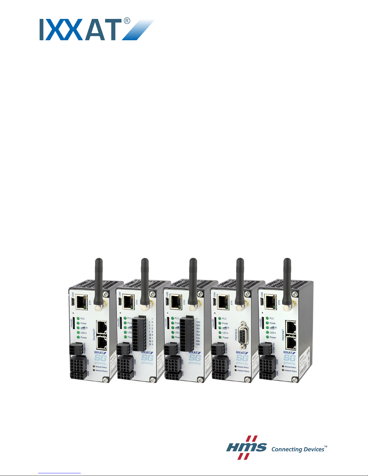
SG Gateway
USER MANUAL
4.04.0450.20000 1.3 ENGLISH
Page 2

Important User Information
Liability
Every care has been taken in the preparation of this document. Please inform HMS Industrial Networks of any inaccuracies or omissions. The data and illustrations found in this document are not binding. We, HMS Industrial Networks, reserve the right to modify our products in line with our policy of continuous product development. The
information in this document is subject to change without notice and should not be considered as a commitment by
HMS Industrial Networks. HMS Industrial Networks assumes no responsibility for any errors that may appear in this
document.
There are many applications of this product. Those responsible for the use of this device must ensure that all the
necessary steps have been taken to verify that the applications meet all performance and safety requirements including any applicable laws, regulations, codes, and standards.
HMS Industrial Networks will under no circumstances assume liability or responsibility for any problems that may
arise as a result from the use of undocumented features, timing, or functional side effects found outside the documented scope of this product. The effects caused by any direct or indirect use of such aspects of the product are
undefined, and may include e.g. compatibility issues and stability issues.
The examples and illustrations in this document are included solely for illustrative purposes. Because of the many
variables and requirements associated with any particular implementation, HMS Industrial Networks cannot assume responsibility for actual use based on these examples and illustrations.
Intellectual Property Rights
HMS Industrial Networks has intellectual property rights relating to technology embodied in the product described
in this document. These intellectual property rights may include patents and pending patent applications in the USA
and other countries.
SG Gateway User Manual 4.04.0450.20000 1.3
Page 3

SG Gateway User Manual 4.04.0450.20000 1.3
Table of Contents
Page
1 User Guide ........................................................................................................................ 3
1.1 Target Audience.............................................................................................................3
1.2 Related Documents .......................................................................................................3
1.3 Document History ..........................................................................................................3
1.4 Conventions ..................................................................................................................4
2 Safety Instructions.......................................................................................................... 5
3 Scope of Delivery ............................................................................................................ 5
4 Product Description ....................................................................................................... 6
4.1 Common Features .........................................................................................................6
4.2 I/O Interface ..................................................................................................................6
4.3 M-Bus Interface .............................................................................................................6
4.4 PROFIBUS Interface......................................................................................................7
4.5 EtherNet/IP Interface......................................................................................................7
4.6 PROFINET Interface ......................................................................................................8
5 Installation ........................................................................................................................ 9
5.1 System Requirements....................................................................................................9
5.2 Wireless via 3G Cellular Modem (Optional)....................................................................10
5.3 Connecting the Device to the Computer......................................................................... 11
5.4 Connecting the Power Connector.................................................................................. 11
5.5 Connecting I/O and M-Bus Interfaces ............................................................................ 11
5.6 Mounting the Device ....................................................................................................12
5.7 Reset the Device ......................................................................................................... 13
6 Configuration .................................................................................................................14
6.1 Configuring the Network Settings ..................................................................................14
6.2 Accessing the Embedded Web Server........................................................................... 16
6.3 Updating the Firmware ................................................................................................. 17
6.4 Configuring SMS Messaging......................................................................................... 18
6.5 Protocol Specific Restrictions........................................................................................ 19
Page 4

SG Gateway User Manual 4.04.0450.20000 1.3
Table of Contents
7 Operation.........................................................................................................................20
7.1 CAN Interface.............................................................................................................. 20
7.2 Serial Interface (COM) ................................................................................................. 20
7.3 Ethernet Interface ........................................................................................................ 21
7.4 I/O Interface ................................................................................................................ 21
7.5 M-Bus Interface ........................................................................................................... 21
7.6 LEDs...........................................................................................................................22
8 Technical Data................................................................................................................ 23
9 Support/Return Hardware........................................................................................... 25
9.1 Support ....................................................................................................................... 25
9.2 Return Hardware ......................................................................................................... 25
10 Disposal........................................................................................................................... 25
A Regulatory Compliance............................................................................................... 27
A.1 EMC Compliance (CE) ................................................................................................. 27
A.2 RoHS Directive............................................................................................................ 27
A.3 Disposal and recycling ................................................................................................. 27
B Open Source Software................................................................................................. 27
Page 5

User Guide 3 (28)
1 User Guide
Please read the manual carefully. Make sure you fully understand the manual before using the
product.
1.1 Target Audience
This documentation is intended for use by skilled staff who are familiar with the applicable national standards of the application field. Exclusively trained staff authorized by the operator is allowed to install, commission and maintain the device. The contents of the user manual must be
made available to any person authorized to use or operate the product.
1.2 Related Documents
Document Author
SG Gateways IEC 61850 Application Note HMS
OpenVPN documentation http://openvpn.net OpenVPN
WEB-PLC — Online Help HMS
For additional related documentation and file downloads see support website at
www.ixxat.com/support.
1.3 Document History
Version Date Description
1.0 May 2017 First release IXXAT product
1.1 September 2017 Combined installation guide and extended user manual
1.2 October 2017 Added information about Open Source Software
1.3 October 2017 Corrected information about PROFINET
SG Gateway User Manual 4.04.0450.20000 1.3
Page 6
User Guide 4 (28)
1.4 Conventions
Instructions and results are structured as follows:
► instruction 1
► instruction 2
➨ result 1
➨ result 2
Lists are structured as follows:
• item 1
• item 2
Bold typeface indicates interactive parts such as connectors and switches on the hardware, or
menus and buttons in a graphical user interface.
This font is used to indicate program code and other
kinds of data input/output such as configuration scripts.
This is a cross-reference within this document: Conventions, p. 4
This is an external link (URL): www.hms-networks.com
Safety advice is structured as follows:
Cause of the hazard!
Consequences of not taking remediate action.
How to avoid the hazard.
Safety signs and signalwords are used dependent on the level of the hazard.
This is additional information which may facilitate installation and/or operation.
This instruction must be followed to avoid a risk of reduced functionality and/or
damage to the equipment, or to avoid a network security risk.
Caution
This instruction must be followed to avoid a risk of personal injury.
WARNING
This instruction must be followed to avoid a risk of death or serious injury.
SG Gateway User Manual 4.04.0450.20000 1.3
Page 7
Safety Instructions 5 (28)
2 Safety Instructions
Caution
The device may only be put into service and operated by qualified personnel.
Risk of interference if used with antenna (wireless)!
In case of interference install device or antenna in other location.
If device is connected directly to the internet (without router), the firewall must be
enabled.
HMS recommends to use encoding via openVPN, if supported by all participants,
to increase the internet safety.
General Safety Notes
► Protect product from moisture and humidity.
► Protect product from too high or too low temperature (see Technical Data, p. 23).
► Protect product from fire.
► Do not throw, drop or try to bend the product.
► Do not paint the product.
► Do not modify or disassemble the product. Service must be carried out by HMS Industrial
Networks.
► Do not use modified products.
► Store products in dry and dust-free place.
3 Scope of Delivery
Included in scope of delivery:
• SG Gateway
• User Manual SG Gateway
• Micro SD card
• 1 x power connector 3-pin
• 1 x CAN connector
• 1 x COM connector
• I/O and M-Bus variant: 1 x I/O connector
• variants with modem: antenna
Dependent on variant and protocol further connectors may be included.
SG Gateway User Manual 4.04.0450.20000 1.3
Page 8
Product Description 6 (28)
4 Product Description
The SG Gateway family is designed for Smart Grid communication, specifically target Demand
Response (networking of industrial electric loads) and Virtual Power Plants (networking of energy resources like biogas plants or combined heat and power units) applications. The IXXAT
SG-gateways are available in different variants.
Information in this document is about the hardware versions ASGxxx-C. Check the
hardware version of the device in use on the product label. For information about
another hardware, contact HMS Industrial Networks.
4.1 Common Features
• Ethernet
• Modbus-TCP Client/Server
• Modbus-RTU Master/Slave
• IEC 61850 Client/Server + GOOSE Publisher/Subscriber (optional)
• IEC 60870-5-104 Client/Server + Redundancy (optional)
• Network Address Translation (NAT)
• Simple Network Management Protocol (SNMP)
• DHCP server
• Web based configuration via browser
• CODESYS network variables
• OpenVPN client
• Diagnostics (Pcap, Ping, DNS lookup etc.)
• Password protection
• Simple network time protocol (SNTP)
• Event log
• Remanent variables
• Timer functionality
4.2 I/O Interface
• 4 x digital inputs
• 4 x digital outputs
4.3 M-Bus Interface
• reads up to 32 energy meters
• 2 x digital inputs
• 2 x digital outputs
SG Gateway User Manual 4.04.0450.20000 1.3
Page 9

Product Description 7 (28)
4.4 PROFIBUS Interface
• 1 x 9-pin D-Sub female connector to PROFIBUS
• supports PROFIBUS DP-V0/DP-V1 functionality
• automatic baud-rate detection
• User Parameterization Data
• Set Slave Address
• ADI access via DP-V1 read/write services
• max. 244 bytes input and 244 bytes output data
• device identity customization
• generic GSD file provided
• Modular Device Mode
• module status LED and network status LED
4.5 EtherNet/IP Interface
• 2 x RJ-45 EtherNet/IP 100 Mbit/s ports available simultaneously
• Generic Device profile
• dual port cut-through switch implemented in the Anybus NP40 processor
• device Level Ring (DLR) Beacon-based
• QuickConnect class B
• CIP energy object support
• CIP safety in preparation (hardware prepared)
• customized identity information
• explicit messaging up to 1500 using Large Forward Open
• multiple I/O assembly
• modular device
• module status LED and network status LED
SG Gateway User Manual 4.04.0450.20000 1.3
Page 10

Product Description 8 (28)
4.6 PROFINET Interface
• dual RJ-45 network ports available simultaneously
• complete PROFINET-IO Real-Time (RT) Class 1 & 3 communication V 2.31
• max. 1440 bytes of input and 1440 bytes of output data
• up to 128 modules
• baud-rate 100 Mbit/s fixed
• SNMP-MIBII support
• generic and PROFINET specific diagnostic support
• PROFIenergy profile
• Media Redundancy Protocol (MRP)
• device identity customization
• PROFINET Fast Start Up
• PROFINET uplink configuration via .GSDML file
• integrated switch allowing for a daisy-chain topology
• module status LED and network status LED
SG Gateway User Manual 4.04.0450.20000 1.3
Page 11

Installation 9 (28)
5 Installation
5.1 System Requirements
The following features are needed on the local computer:
• Ethernet network interface
• Microsoft Windows XP/Vista/7/10
• internet connection
• web-browser:
– Mozilla Firefox (recommended)
– Microsoft Internet Explorer 8 or later (version 9 or later recommended)
– Microsoft Edge
– Google Chrome
– Apple Safari
– Opera
• Chiptool, available on download section on IXXAT website: www.ixxat.com/sg-gw-
download
The WEB-PLC software runs on any up-to-date web browser on any PC operating system. The
Chiptool, used to determine or configure the device’s IP address, runs on Windows.
Firmware
The firmware is constantly improved and expanded. To configure the device the latest firmware
must be downloaded on the device. For more information about updating the firmware see Up-
dating the Firmware, p. 17.
WEB PLC Help
After connecting the SG Gateway and accessing the Embedded Web the WEB PLC Online
Help is available via the button
in the WEB PLC. It is also possible to download a WEB PLC
Offline Help from the support area on www.ixxat.com.
SG Gateway User Manual 4.04.0450.20000 1.3
Page 12

Installation 10 (28)
5.2 Wireless via 3G Cellular Modem (Optional)
Caution
This equipment emits RF energy in the ISM (Industrial, Scientific, Medical) band.
Make sure that all medical devices used in proximity to this device meet
appropriate susceptibility specifications for this type of RF energy.
To use the wireless function the cellular modem must be enabled and a SIM card and an antenna must be installed.
5.2.1 Inserting the SIM Card
Fig. 1 Inserting the SIM card
► Make sure, that the device is switched off.
► Insert the SIM card at the rear of the device.
► Push the SIM card until it locks.
5.2.2 Installing the Antenna
Use antenna exclusively in areas where operation of wireless equipment is
allowed.
If antenna is installed outdoors, make sure to be in compliance of lightning
protection standard VDE V0185.
► Observe the EMC lightning protection zone concept.
► Make sure, that the antenna has at least 20 cm distance to persons or other antennas (rec-
ommended radiological limits).
► Make sure, that the device is switched off.
► Screw the antenna on connector Antenna.
SG Gateway User Manual 4.04.0450.20000 1.3
Page 13

Installation 11 (28)
5.3 Connecting the Device to the Computer
► Connect Ethernet port (ETH) of the device directly to the Ethernet port of the computer or
via hub or switch.
5.4 Connecting the Power Connector
Damaged device caused by reverse polarity or wrong power supply!
Make sure that power is connected with correct polarity and that power supply is of
recommended type.
The power supply must be a grounded circuit (PELV) and a limited power source according to
EN 60950-1 Cap. 2.5 or the device must be provided with an anti-surge fuse of 2 A. The digital
I/Os are provided with a detached anti-surge fuse of 4 A.
Fig. 2 Power connector
Pin Allocation of Power Connector
Pin Description
FE Functional earth
GND Ground
VCC 24 V DC
► Unplug the connector.
► Connect cables to the power connector.
► Plug the power connector to the power supply jack of the device (1).
5.5 Connecting I/O and M-Bus Interfaces
When using an I/O interface or a M-Bus interface the interface must be connected to supply
voltage.
Fig. 3 Pin allocation
► Apply voltage of 24 V (VCC) to the pin + of the interface.
► Apply ground to the pin - of the interface.
COM
VCC
GND
FE
CAN
1
+
-
SG Gateway User Manual 4.04.0450.20000 1.3
Page 14

Installation 12 (28)
5.6 Mounting the Device
Damage caused by overheating!
Ensure adequate air circulation. Observe the recommended mounting distance.
Use in dry rooms exclusively.
The device is designed for installation on a grounded 35 mm DIN rail.
Fig. 4 Mounting the device
Recommended mounting distance:
• If venting slots are covered: 2 cm distance on top and bottom
• If venting slots are covered about 50%: 1 cm distance on top and bottom.
► Ensure adequate air circulation.
► Make sure, that the device is connected to power supply (see Connecting the Power Con-
nector, p. 11).
► Make sure, that the device is connected to the computer (see Connecting the Device to the
Computer, p. 11).
► Use top hat rail mounting.
➨ After the installation the housing of the device is connected to functional earth.
SG Gateway User Manual 4.04.0450.20000 1.3
Page 15

Installation 13 (28)
5.7 Reset the Device
Fig. 5 Reset the device
All settings are lost when device is reset.
► Disconnect the device from power supply.
► To restore the factory settings, press and hold the Reset button (1) with a pointed object.
► While holding the Reset button (1) connect the device to power supply.
► Hold the Reset button until all LEDs are flashing twice. This can take up to 20 seconds.
➨ When the reset is acknowledged all LEDs are flashing twice.
► Release the Reset button (1).
► Wait until the device is started up. Do not disconnect the power supply before the device is
started up.
1
SG Gateway User Manual 4.04.0450.20000 1.3
Page 16

Configuration 14 (28)
6 Configuration
6.1 Configuring the Network Settings
To be able to access the embedded web server, the device must have a valid IP address known
to HMS Industrial Networks.
Fig. 6 Chiptool
► Make sure that device is connected to computer (see Connecting the Device to the Com-
puter, p. 11).
► Make sure that Chiptool is downloaded (see System Requirements, p. 9).
► Start Chiptool.
➨ Chiptool scans for SG Gateways on the local network.
➨ MAC IDs of the found devices are displayed in a list.
► Check MAC ID of device in use on label on the housing.
SG Gateway User Manual 4.04.0450.20000 1.3
Page 17

Configuration 15 (28)
► Right-click on the MAC ID in the Chiptool list and select IP configuration in the context
menu.
➨ Current IP configuration of the device is displayed.
➨ By default the device tries to get an IP address from a DHCP server at start.
Fig. 7 IP configuration
► Check if the current settings match the needs of the network (ask network administrator for
further information).
► If necessary uncheck Use DHCP checkbox and set IP address manually.
► Click Config button.
➨ Chiptool asks for a password.
► Enter default password ixxat.
► If a firewall is run, make sure that it does not block any network functions of the Chiptool.
SG Gateway User Manual 4.04.0450.20000 1.3
Page 18

Configuration 16 (28)
6.2 Accessing the Embedded Web Server
► Enter IP address of the device in use into a web browser.
➨ Introduction page is shown shortly.
➨ Home page of the WEB-PLC is opened.
Fig. 8 Accessing the embedded webserver
The home page shows the following information:
• overview of the status of the device
• current values of the I/Os
• information on the device hardware and software
• information on special components such as the cellular modem or OpenVPN
► To open the WEB-PLC editor, click Editor
.
➨ Website requests user name and password.
► Enter ixxat (default) for both user name and password.
➨ WEB-PLC Editor is opened.
Password has to be changed after first login (see WEB-PLC Online Help).
► To go to the page Settings, click icon Settings
.
➨ Event Log is opened, which displays all events (information messages, warnings and
errors) generated by the device.
► For detailed information about the settings possibilities and event log messages open the
WEB-PLC Online Help via the button
.
SG Gateway User Manual 4.04.0450.20000 1.3
Page 19

Configuration 17 (28)
6.3 Updating the Firmware
The firmware is constantly improved and expanded. To configure the device the latest firmware
must be downloaded on the device. For more information about updating the firmware see
WEB PLC Online Help — Settings — Update.
Don’t switch off power, reset the device or perform any other operations while the
update is in progress.
The device restarts several times during the update and error messages may
occur.
Online Update
► To check the current firmware version, open tab Update in Settings.
► Check if newer version is available on www.ixxat.com/sg-gw-download.
► If newer version is available, download and extract the firmware update zip file.
► Make sure, that the SD card is plugged in.
Upload may fail if SD card is plugged in after start-up!
If the SD card is plugged in after start-up, reboot the device before updating.
► To start the update, select the update package in field Update package and click Start
update.
➨ Start-up directory is created on SD card.
➨ Device is programmed with the new software.
➨ When firmware is updated, the index page is opened.
► To make sure, that the new version of the website is shown, clear the browser cache with
Ctrl + F5.
Offline Update
If the update package is stored on the SD card, updating is possible without access to the WEB
PLC.
► Make sure that the update package update.cup is stored in the com.tom directory on the
SD card.
► Connect the device to power supply and start up the device.
► Press and hold the Reset button with a pointed object.
➨ When the update is started all LEDs are flashing twice.
► Release the Reset button (1).
► Wait until the update is applied. Do not disconnect the power supply before the update is
applied.
SG Gateway User Manual 4.04.0450.20000 1.3
Page 20

Configuration 18 (28)
6.4 Configuring SMS Messaging
The SG Gateway with 3G cellular modem is capable of sending and receiving messages. Currently only short messages via the mobile network (SMS) are supported.
► Make sure, that the cellular modem is enabled.
► For information how to add messages, open WEB-PLC Online Help — Settings —
Settings — PLC — Messages.
If messages are added in the settings:
► In WEB-PLC editor add the units Send Msg 0 and Recv Msg 0 to the current application.
➨ Send Msg 0 transmits the first configured message when its transmitting trigger input
port (Snd) is high.
➨ Recv Msg 0 puts out a high signal on its output port when the first configured message
is received.
► To send a message every time the receive message is processed, connect Send Msg 0
and Recv Msg 0.
SG Gateway User Manual 4.04.0450.20000 1.3
Page 21

Configuration 19 (28)
6.5 Protocol Specific Restrictions
For information about the setting possibilities of the individual protocols see WEB-PLC —
Online Help — I/Os.
The number of devices and values that can be defined in the various protocols is limited.
Modbus
• Client: 128 devices, 4096 values (max. 8129 array elements)
• Server: 4096 values (max. 8129 array elements)
• TCP Server/Slave: up to 16 Modbus TCP Client/Master can be connected
• RTU Slave: one Modbus RTU Master and 4096 values can be connected
• RTU Master: up to 128 devices and 4096 values can be connected
IEC 60870-5-104
• Client: 32 devices, 4096 values (max. 8129 array elements)
• Server: 4096 values (max. 8129 array elements)
IEC 61850
• Client: 128 devices, 4096 values
• Server: 4096 values
SNMP
• up to 128 agents and 4096 values
PROFIBUS
• up to 128 modules and 244 values (per direction)
PROFINET
• up to 128 modules and 1440 values (per direction)
EtherNet/IP
• up to 128 modules and 1448 values (per direction)
SG Gateway User Manual 4.04.0450.20000 1.3
Page 22

Operation 20 (28)
7 Operation
Fig. 9 Device overview
1 CAN interface
2 Serial interface RS232/RS485
3 Power connector
4 Micro SD slot
5
Ethernet interface
6 Antenna connector (only in version with modem)
7 LED array
7.1 CAN Interface
If the device is last in line in the bus topology a termination is required. The termination resistor
needs to be 120 Ohm and must be inserted between pin 2 and pin 4 of the CAN interface.
Pin Allocation CAN
Pin Signal
1 CAN-high
2 TERM
3 CAN-low
4 TERM
7.2 Serial Interface (COM)
The serial interface is only used for Modbus RTU.
There are no resistors for line termination and line polarization in the device. The device itself
does not need line polarization.
If a device in RS485 mode is last in line in the bus topology a termination is required. The termination resistor needs to be 120 Ohm and must be inserted between pin 3 and pin 7 of the serial
interface.
Pin Allocation RS232/RS485
Pin Signal
1 GND
2 CTS
3 B
4 TXD
5 A
6 RTS
7 TERM_B
8 RXD
HTE
COM
Portal
PLC
LED 4
Power
VCC
GND
FE
Antenna
microSD
3G
USB
CAN
2
4
5
7 6
1
3
8
71
2
4
3
2
P ins
1
SG Gateway User Manual 4.04.0450.20000 1.3
Page 23

Operation 21 (28)
7.3 Ethernet Interface
Green LED Connection indication
Yellow LED Activity indication
7.4 I/O Interface
Only available with the I/O device variant.
Fig. 10 I/O interface
Digital I/Os
+
24 VDC IN
I0-I3 Digital pulse input, sink
Q0-Q3 Digital output, source
-
M-Bus
Make sure, that voltage (24 V) is applied to pin + and ground to pin - (see
Connecting I/O and M-Bus Interfaces, p. 11).
7.5 M-Bus Interface
Only available with the M-Bus device variant.
Fig. 11 M-Bus interface
Digital I/Os
+
24 VDC IN
S01, S02 Digital pulse input, sink
Out1, Out2 Digital output, source
MB+, MB- M-Bus
-
Ground
Make sure, that voltage (24 V) is applied to pin + and ground to pin - (see
Connecting I/O and M-Bus Interfaces, p. 11).
I
I
I
I
Q
Q
Q
Q
+
0
1
2
3
0
1
2
3
-
S02 S0 2 +
S01 S0 1 +
Out 2
Out 1
M B MB +
+
-
SG Gateway User Manual 4.04.0450.20000 1.3
Page 24

Operation 22 (28)
7.6 LEDs
7.6.1 PLC LED
The PLC LED indicates the status of the PLC.
LED Description
Off No program loaded, PLC not running
Slowly blinking (0.5 Hz) Program loaded, PLC not running
On Program loaded, PLC running
Fast blinking (4 Hz) Task cycle of PLC violated (e.g. cycle time too short in relation to complexity of pro-
gram, check duty cycle of PLC in status bar of editor), see WEB-PLC-Help — Status
LEDs for more information
7.6.2 Portal LED
The IXXAT SG Gateway supports the use of the com.tom portal. The Portal LED indicates the
status of the portal connection. For further information see WEB-PLC-Help — Status LEDs.
7.6.3 GSM LED
The GSM LED indicates the status of the cellular modem connection.
LED Description
Off Connection not enabled
Slowly blinking (0.5 Hz) Connection is being established.
On Connection is established.
7.6.4 LED 4
If WiFi functionality is available (optional), the LED 4 indicates the status of the WLAN
connection.
LED Description
Off WLAN connection not enabled.
Slowly blinking (0.5 Hz) Connection is being established.
On Connection is established.
Fast blinking (4 Hz) Fatal error, cellular modem driver no longer tries to establish a connection.
7.6.5 Power LED
LED Description
Off Device not supplied with power
On Device is supplied with power
SG Gateway User Manual 4.04.0450.20000 1.3
Page 25

Technical Data 23 (28)
8 Technical Data
CPU IPC@CHIP® SC145, i.Mx6, 32-bit processor with 528 MHz, 128 MB RAM
(DDR3), 64 MB flash disk
Dimensions (W x L x H) 46 x 105 x 78 mm
Weight 700 g
Operating temperature -20 to +60 °C
Protection class electrical shock Class III
EMC emission IEC 61000-6-3
EMC immunity IEC 61000-6-2
Power supply 24 VDC (±15 %), Weidmüller BL 3.50/03 connector
Housing material Powder-coated steel sheet, RAL 7021, dull finish
Real-time clock Backed by lithium rechargeable battery
SD card interface microSD card SD/SDHC, push/push slot
Ethernet interface 10/100 BaseT, RJ45
Serial interface 1 x RS232/RS485 (selectable), Weidmüller BL 3.50/08 connector
USB interface USB 2.0, Micro USB (type B) connector, OTG support
CAN interface Weidmüller BL 3.50/04 connector
Protection class IP 20, NEMA rating 1
Software operating system IPC@CHIP® RTOS-LNX Real-time operating system
UMTS Modem
Frequencies GSM/GPRS/EDGE Quad band: 850/900/1800/1900 MHz
Frequencies UMTS/HSPA+ Seven band: 800/850/900/AWS 1700/1900/2100 MHz
SIM card Full-size (1FF), push/push slot
Antenna interface SMA female
Digital I/O
Digital inputs 4 x sink, TRUE: 15 V DC min, FALSE: 5 V DC max, no potential isolation
Digital outputs 4 x transistor (high-side), short circuit and overload resistant, no potential
isolation
Connector Weidmüller BL 3.50/10
Current consumption ≤ 100 mA at 24 V DC (without I/Os) / with modem: ≤ 140 mA at 24 V DC (with-
out I/Os)
≤ 500 mA at 24 V DC per digital I/O
PROFINET
PROFINET interface 2–port PROFINET IRTswitch, 10/100BaseT
Connector 2 x RJ45
Profiles PROFINET I/O
Current consumption 200 mA at 24 V DC / with modem: 240 mA at 24 V DC
PROFIBUS
PROFIBUS interface PROFIBUS DP-V0/DP-V1
Connector D-Sub9
Current consumption 160 mA at 24 V DC / with modem: 200 mA at 24 V DC
EtherNet/IP
EtherNet/IP interface 2-port cut-through switch, 10/BaseT
Connector 2 x RJ45
Profiles Generic device
Current consumption 200 mA at 24 V DC / with modem: 240 mA at 24 V DC
SG Gateway User Manual 4.04.0450.20000 1.3
Page 26

Technical Data 24 (28)
M-Bus
M-Bus interface 1 channel, up to 64 devices, max. distance 5 km, 300 bit/s, AWG 15
Digital S0 inputs 2 channels, 10 mA, max. frequency 50 Hz
Digital outputs 2 channels (transistor, high side), 24 V DC, max. 500 mA
short circuit and overload resistant, no potential isolation
Connector Weidmüller BL 3.50/10
Current consumption ≤ 100 mA at 24 V DC (without M-Bus and I/Os) / with modem: ≤ 140 mA at 24
V DC (without M-Bus and I/Os)
≤ 250 mA at 24 V DC M-Bus
≤ 500 mA at 24 V DC per digital I/O
SG Gateway User Manual 4.04.0450.20000 1.3
Page 27

Support/Return Hardware 25 (28)
9 Support/Return Hardware
Observe the following information in the support area on www.ixxat.com:
• information about products
• FAQ lists
• installation notes
• updated product versions
• updates
9.1 Support
► For problems or support with the product request support at www.ixxat.com/support.
► If required use support phone contacts on www.ixxat.com.
9.2 Return Hardware
► Fill in the form for warranty claims and repair on www.ixxat.com.
► Print out the Product Return Number (PRN resp. RMA).
► Pack product in a physically- and ESD-safe way, use original packaging if possible.
► Enclose PRN number.
► Observe further notes on www.ixxat.com.
► Return hardware.
10 Disposal
► Dispose of product according to national laws and regulations.
► Observe further notes about disposal of products on www.ixxat.com.
SG Gateway User Manual 4.04.0450.20000 1.3
Page 28

This page intentionally left blank
Page 29

Appendix A: Regulatory Compliance 27 (28)
A Regulatory Compliance
A.1 EMC Compliance (CE)
The product is in compliance with the Electromagnetic Compatibility Directive. More information
and the Declaration of Conformity is found at www.ixxat.com.
A.2 RoHS Directive
The product is in compliance with the RoHs Directive 2002/95/EC (Restriction of the use of certain hazardous substances in electrical and electronic equipment).
A.3 Disposal and recycling
You must dispose of this product properly according to local laws and regulations. Because this
product contains electronic components, it must be disposed of separately from household
waste. When this product reaches its end of life, contact local authorities to learn about disposal
and recycling options, or simply drop it off at your local HMS office or return it to HMS.
For more information, see www.hms-networks.com.
B Open Source Software
The IXXAT SG Gateway uses open source software. For the list of the used Open Source Software see WEB PLC Online Help — Open Source Software. The Open Source Software Code
can be downloaded from the support area Energy – SG-gateways on www.ixxat.com.
SG Gateway User Manual 4.04.0450.20000 1.3
Page 30

last page
© 2017 HMS Industrial Networks AB
Box 4126
300 04 Halmstad, Sweden
info@hms.se 4.04.0450.20000 1.3.5953 / 2017-10-26T13:52:33
 Loading...