

Page 1
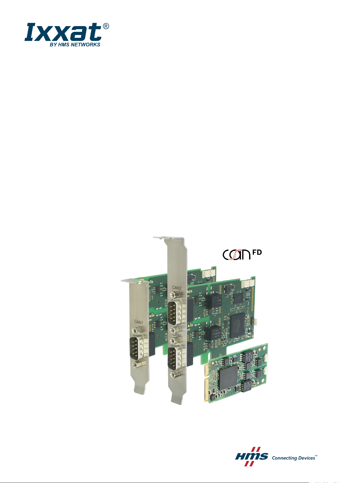
PPCC CCAANN IInntteerrffaaccee
CCAANN--IIBB SSeerriieess ffoorr PPCCII//PPCCIIeexxpprreessss
USER MANUAL
4.01.0230.20000 3.2 en-US ENGLISH
Page 2

Important User Information
Liability
Every care has been taken in the preparation of this document. Please inform HMS Industrial Networks of any
inaccuracies or omissions. The data and illustrations found in this document are not binding. We, HMS Industrial
Networks, reserve the right to modify our products in line with our policy of continuous product development. The
information in this document is subject to change without notice and should not be considered as a commitment by
HMS Industrial Networks. HMS Industrial Networks assumes no responsibility for any errors that may appear in this
document.
There are many applications of this product. Those responsible for the use of this device must ensure that all the
necessary steps have been taken to verify that the applications meet all performance and safety requirements
including any applicable laws, regulations, codes, and standards.
HMS Industrial Networks will under no circumstances assume liability or responsibility for any problems that may
arise as a result from the use of undocumented features, timing, or functional side effects found outside the
documented scope of this product. The effects caused by any direct or indirect use of such aspects of the product
are undefined, and may include e.g. compatibility issues and stability issues.
The examples and illustrations in this document are included solely for illustrative purposes. Because of the many
variables and requirements associated with any particular implementation, HMS Industrial Networks cannot assume
responsibility for actual use based on these examples and illustrations.
Intellectual Property Rights
HMS Industrial Networks has intellectual property rights relating to technology embodied in the product described in
this document. These intellectual property rights may include patents and pending patent applications in the USA
and other countries.
PC CAN Interface User Manual
4.01.0230.20000 3.2 en-US
Page 3

Table of Contents
Page
1 User Guide........................................................................................................................... 3
1.1 Target Group.......................... .................................................................................. ....... 3
1.2 Related Documents ......... ................ ......... ................ ........................................................3
1.3 Document History .. ......... ................ .................................................................. ...............3
1.4 Trademark Information ...................................... ......... ................ ......... ................ ......... ....3
1.5 Conventions.. ......................... .................................................................................. ....... 4
2 Safety Instructions .............................................................................................................. 5
2.1 Information on EMC ................... ................ ......... ................ ......... ................ ....................5
2.2 General Safety Instructions ............... ......... ................ ........................................................5
2.3 Intended Use......... ......... ................ ......... ......................................................... ...............5
3 Scope of Delivery ................................................................................................................ 5
4 Product Description ............................................................................................................ 6
4.1 CAN-IB100/200/PCIe and CAN-IB300/400/PCI ... ......................................................... ...........6
4.2 CAN-IB500/600/PCIe .......................... ......................... ......................... ............................ 7
4.3 CAN-IB120/PCIe Mini and CAN-IB520/PCIe Mini . ......... ................ ......... ................ ................. 8
5 Installation........................................................................................................................... 9
5.1 Installing the Software ..... ................ ......... ................ ......................................... ...............9
5.2 Installing the Hardware ...... .................................................................. ................ ......... ....9
6 Connections ....................................................................................................................... 10
6.1 Overview ......................................... ................ ......... ................ ......... ................ ........... 10
6.2 CAN Bus ..................................................... ......................... ......................... ................ 10
6.3 Expansions... ................ ......... ................ .................................................................. ...... 11
6.4 PCIe Mini.................... ......................................................... ......................... ................ 12
7 Expansions ......................................................................................................................... 13
7.1 Fieldbus Expansion ............ ......... ................ ......... ................ ......... .................................. 13
7.2 CAN Expansion Board .......................................................... ......... ................ ......... ......... 15
7.3 MultiCAN Expansion .. ......................... ............................................................................ 16
8 Technical Data................................................................................................................... 20
8.1 PCI/PCIe .................................................................... ......................... ......................... . 20
8.2 Mini PCIe.................... ......................................................... ......................... ................ 20
PC CAN Interface User Manual
4.01.0230.20000 3.2 en-US
Page 4

9 Support/Return Hardware................................................................................................ 21
9.1 Support ....................................................... ......... ................ ......... ................ ......... ...... 21
9.2 Return Hardware .................... .................................................................................. ..... 21
10 Disposal.............................................................................................................................. 21
A Regulatory Compliance ..................................................................................................... 23
A.1 EMC Compliance (CE) .......... ......................... ......................... ......................................... 23
A.2 FCC Compliance Statement . ......... ................ ......... ................ ........................................... 23
A.3 Disposal and recycling...................................... ................ ......... ................ ......... ............. 24
PC CAN Interface User Manual
4.01.0230.20000 3.2 en-US
Page 5

User Guide 3 (26)
1 User Guide
Please read the manual carefully. Make sure you fully understand the manual before using the
product.
1.1 Target Group
This manual addresses trained personnel who are familiar with CAN, CAN FD and the applicable
standards. Only ESD trained staff is authorized to install the interface. The contents of the
manual must be made available to any person authorized to use or operate the product.
1.2 Related Documents
Document
User Manual Expansions for CAN-IB Series for PCI/PCIexpress
Installation Guide VCI Driver
1.3 Document History
Author
HMS
HMS
Version
3.0
3.1
3.2
Date
April 2016 Revised and edited in new design
September 2017 Removed obsolete variants, added CAN-FD variants, related documents, target
March 2019 Layout changes
1.4 Trademark Information
Ixxat®is a registered trademark of HMS Industrial Networks. All other trademarks mentioned in
this document are the property of their respective holders.
Description
group and intended use
PC CAN Interface User Manual
4.01.0230.20000 3.2 en-US
Page 6
User Guide 4 (26)
1.5 Conventions
Instructions and results are structured as follows:
► instruction 1
► instruction 2
→ result 1
→ result 2
Lists are structured as follows:
• item 1
• item 2
Bold typeface indicates interactive parts such as connectors and switches on the hardware, or
menus and buttons in a graphical user interface.
This font is used to indicate program code and other
kinds of data input/output such as configuration scripts.
This is a cross-reference within this document: Conventions, p. 4
This is an external link (URL): www.hms-networks.com
Safety advice is structured as follows:
Cause of the hazard!
Consequences of not taking remediate action.
How to avoid the hazard.
Safety signs and signalwords are used dependent on the level of the hazard.
This is additional information which may facilitate installation and/or operation.
This instruction must be followed to avoid a risk of reduced functionality and/or damage
to the equipment, or to avoid a network security risk.
Caution
This instruction must be followed to avoid a risk of personal injury.
WARNING
This instruction must be followed to avoid a risk of death or serious injury.
PC CAN Interface User Manual
4.01.0230.20000 3.2 en-US
Page 7

Safety Instructions 5 (26)
2 Safety Instructions
2.1 Information on EMC
Risk of interference to radio and television if used in office or home environment!
Use exclusively included accessories.
Make sure that the shield of the interface is connected with the device plug and the plug
on the other side.
Use exclusively shielded cables.
2.2 General Safety Instructions
► Protect product from moisture and humidity.
► Protect product from too high or too low temperature (see Technical Data, p. 20).
► Protect product from fire.
► Do not paint the product.
► Do not modify or disassemble the product. Service must be carried out by HMS Industrial
Networks.
► Store products in dry and dust-free place.
2.3 Intended Use
The interfaces are used to connect computer systems to CAN and LIN networks. They are
intended for the installation in computer systems with closed housings.
3 Scope of Delivery
Included in the scope of delivery of standard variant:
• PC CAN interface
• CD with VCI driver and example application
• Installation Guide VCI Driver
• User Manual PC CAN Interface
PC CAN Interface User Manual
4.01.0230.20000 3.2 en-US
Page 8
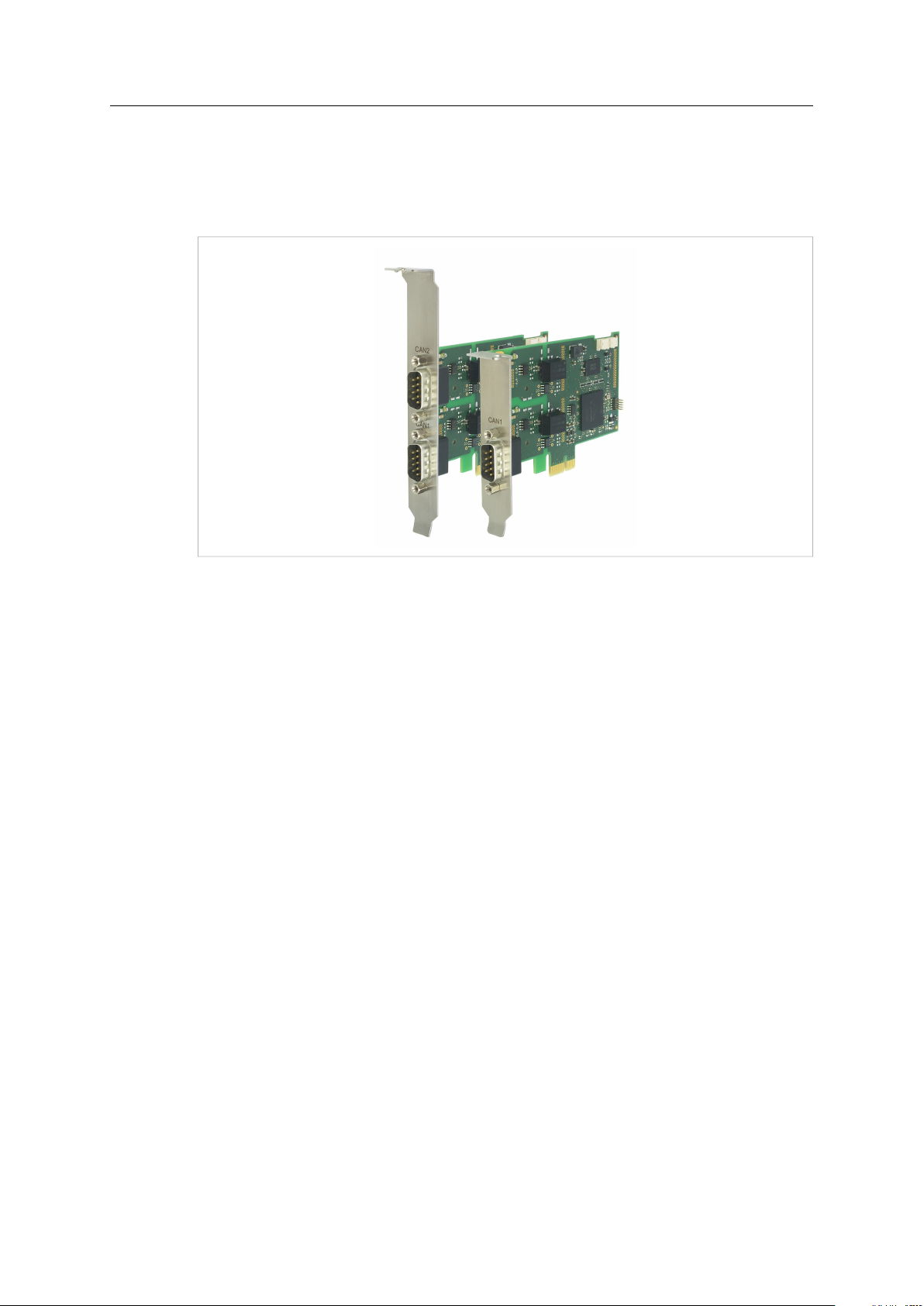
Product Description 6 (26)
4 Product Description
PCIe interfaces (apart from PCIe Mini) are available as standard and low-profile version. PCI
interfaces are available as standard version. The low-profile version is expandable with a D-Sub 9
connector on a second slot bracket.
Fig. 1 Standard and low-profile version
4.1 CAN-IB100/200/PCIe and CAN-IB300/400/PCI
Common Features
• available with 1 or 2 CAN channels
• expandable up to 4 CAN channels
• ISO 11898-2 CAN bus coupling (high-speed)
• expandable with ISO 11898-3 low-speed CAN
• expandable with LIN (CAN-IB200/PCIe, CAN-IB400/PCI)
CAN-IB100/200/PCIe
• single Lane (x1) PCI Express CAN Interface
• CAN-IB100/PCIe, passive interface
• CAN-IB200/PCIe, active interface
• PCI Express connector compliant with the specification PCI Express Card Electromechanical
Specification version 1.1 , operation in any PCI Express slot (x1, x4, x8, x16) possible
• standard version: optionally galvanically isolated
low-profile version: galvanically isolated
PC CAN Interface User Manual
4.01.0230.20000 3.2 en-US
Page 9

Product Description 7 (26)
CAN-IB300/400/PCI
• PCI CAN Interface
• 5 V and 3.3 V compatible
• CAN-IB300/PCI, passive interface
• CAN-IB400/PCI, active interface
• PCI interface compliant with PCI local bus specification Rev. 2.2
• galvanically isolated
4.2 CAN-IB500/600/PCIe
Common Features
• supports CAN-FD (ISO and non-ISO) and CAN 2.0A/B
• ISO 11898-2 CAN bus coupling (high-speed)
• expandable with ISO 11898-3 low-speed CAN
• galvanically isolated
CAN-IB500/PCIe
• available with 1 CAN channel
• Single Lane (x1) PCI Express CAN Interface
• passive interface
• PCI express connector compliant with the specification PCI Express Card Electromechanical
Specification version 1.1 , operation in any PCI Express slot (x1, x4, x8, x16) possible
CAN-IB600/PCIe
• available with 1 or 2 CAN channels
• Single Lane (x1) PCI Express CAN Interface
• active interface
• PCI express connector compliant with the specification PCI Express Card Electromechanical
Specification version 1.1 , operation in any PCI Express slot (x1, x4, x8, x16) possible
• expandable with LIN
PC CAN Interface User Manual
4.01.0230.20000 3.2 en-US
Page 10

Product Description 8 (26)
4.3 CAN-IB120/PCIe Mini and CAN-IB520/PCIe Mini
Common features
• Single lane (x1) PCI express card
• PC interface compliant with PCI express base specification, revision 1.1
• form factor F2: Full-mini with bottom-side keep outs
• dimensions according to PCI express Mini Card electromechanical specification, revision 1.2
• ISO 11898-2 CAN bus coupling (high-speed)
CAN-IB120/PCIe Mini
• available with 1 or 2 CAN channels
• optionally galvanic isolated
CAN-IB520/PCIe Mini
• 1 CAN-FD channel, switchable ISO CAN-FD, non-ISO CAN-FD, CAN 2.0A/B
• galvanically isolated
PC CAN Interface User Manual
4.01.0230.20000 3.2 en-US
Page 11

Installation 9 (26)
5 Installation
5.1 Installing the Software
For the operation of the interface a driver is needed.
Windows
► Install the VCI driver (see Installation Guide VCI Driver).
Linux and Real-Time Operating Systems
► Observe information about supported operating systems and interfaces on www.ixxat.com.
5.2 Installing the Hardware
Risk of ESD damages caused by improper handling!
Use ESD protective measures to avoid equipment damage.
► Make sure that the VCI driver is installed.
► Turn off the computer.
► Pull the power cord.
► Open the computer case according to the instructions of the computer manufacturer.
► Determine the corresponding slot.
► Plug PCI/PCIe connector in the corresponding slot, without using force.
► Make sure that the interface is securely held in the computer.
► Close the computer case.
→ Hardware installation is complete.
PC CAN Interface User Manual
4.01.0230.20000 3.2 en-US
Page 12

Connections
6
3
1
4 5
2
6 Connections
6.1 Overview
Fig. 2 Connections
10 (26)
1 CAN 1
2
CAN 2 (exclusively in standard version)
3
Fieldbus expansion connector channel 2 (option)
4
Fieldbus expansion connector channel 1 (option)
5
PCI/PCIe connector
6
Expansion board connector (option)
6.2 CAN Bus
The bus coupling can optionally be galvanically isolated. With galvanic isolation the shield of the
CAN connector is connected to CAN ground through a 1 MΩ resistor and a 10 nF capacitor. The
shields of the CAN connectors are connected directly together.
For a not galvanically isolated interface, the CAN ground and PC ground are at the same potential.
For best noise immunity use shielded CAN cables.
Pin Allocation D-Sub 9 Connector
Pin no. Signal Via fieldbus expansion
1
2
3 CAN GND
4
5
6
7
8
9
—
CAN-Low (high-speed)
—
— —
— —
CAN-High (high-speed)
—
—
CAN-Low (low-speed)
—
—
CAN-High (low-speed)
—
LIN
VBAT
(8-18 V DC)
LIN
PC CAN Interface User Manual
4.01.0230.20000 3.2 en-US
Page 13

Connections
1
11 (26)
Low-Profile Version
Fig. 3 Low-profile version
In the low-profile version, only the D-Sub 9 connector of CAN 1 is implemented. It is possible to
output the signals of CAN 2 to a second slot bracket.
► To connect the second slot bracket to the interface, plug the ribbon cable in connector (1)
on the interface and in the connector on the second slot bracket.
6.3 Expansions
The fieldbus expansion connectors can be used to extend each CAN circuit with fieldbus
expansions for additional fieldbuses (exclusively galvanically isolated interfaces). The signals of
the additional fieldbuses are applied to the corresponding CAN connector.
The CAN expansion board connector can be used to connect a CAN expansion board that can
provide up to two additional CAN interfaces and fieldbus expansions.
PC CAN Interface User Manual
4.01.0230.20000 3.2 en-US
Page 14

Connections
2
3
1
6.4 PCIe Mini
Fig. 4 Connections PCIe Mini
1 CAN 1, Pin 1
2 CAN 2, Pin 1
3
PCIe Mini card connector
12 (26)
Pin Allocation CAN Connector
Pin no. Signal Color
1
2 CAN-Low
3 CAN GND
CAN-High Red
Yellow
Black
The CAN connector type is SM03B-SURS-TF by JST. The counterpart is 03SUR-32S by JST. A preassembled open-style cable for each CAN connector is included.
PC CAN Interface User Manual
4.01.0230.20000 3.2 en-US
Page 15

Expansions
7 Expansions
7.1 Fieldbus Expansion
Fig. 5 Fieldbus expansion
If there is a low-speed CAN transceiver on the fieldbus expansion, it is possible to switch via
software between the high-speed CAN transceiver on the interface and the low-speed CAN
transceiver on the fieldbus expansion. The signals of the fieldbus modules are connected to the
appropriate D-Sub 9 connector.
Simultaneous operation of low-speed CAN and LIN is also possible.
13 (26)
Use fieldbus expansions exclusively in conjunction with galvanically isolated CAN channels.
If fieldbus expansions are used, CAN 1 high-speed and LIN 1 have the same GND.
7.1.1 Compatibility
Supported fieldbuses Compatible CAN interface (galvanically isolated)
CAN low-speed
LIN
CAN low-speed and LIN
CAN-IB100/200/PCIe
CAN-IB300/400/PCI
CAN-IB500/600/PCIe
CAN expansion board
CAN-IB200/600/PCIe
CAN-IB400/PCI
CAN-IB200/600/PCIe
CAN-IB400/PCI
PC CAN Interface User Manual
4.01.0230.20000 3.2 en-US
Page 16

Expansions
1
2
4
3
7.1.2 Installation
Fig. 6 CAN interface with fieldbus expansions
1
Fieldbus expansion channel 2
2
Fieldbus expansion connector channel 2
3
Fieldbus expansion channel 1
4
Fieldbus expansion connector channel 1
14 (26)
► Plug the expansion in the corresponding expansion connector.
► Make sure that the expansion is properly inserted in the socket.
→ Interface detects the installed expansions automatically.
► If the expansion is not detected automatically, check if the expansion is properly inserted.
► Observe product description and further information on www.ixxat.com.
PC CAN Interface User Manual
4.01.0230.20000 3.2 en-US
Page 17

Expansions
1
2
3 4
5
6
7
7.2 CAN Expansion Board
Fig. 7 Expansion board with fieldbus expansions
1 CAN 3
2 CAN 4
3
Fieldbus expansion channel 4
4
Fieldbus expansion connector channel 4
5
Fieldbus expansion channel 3
6
Fieldbus expansion connector channel 3
7
Expansion board connector
15 (26)
The CAN expansion board provides the following options:
• increase the number of available CAN channels up to four
• increase with additional fieldbus expansions
As an option the bus coupling can be galvanically isolated.
The CAN expansion board is available as standard or low-profile version.
7.2.1 Compatibility
The CAN expansion board is compatible with the following, galvanically isolated two channel
CAN interface:
• CAN-IB100/PCIe
• CAN-IB200/PCIe
• CAN-IB300/PCI
• CAN-IB400/PCI
7.2.2 Installation
► Connect the CAN expansion board to the CAN interface with the provided ribbon cable.
► Make sure that the ribbon cable is in right orientation.
PC CAN Interface User Manual
► For pin allocation of D-Sub 9 connector see CAN Bus, p. 10.
4.01.0230.20000 3.2 en-US
Page 18

Expansions
7.2.3 Fieldbus Expansions
The fieldbus expansion connectors can be used to extend each CAN circuit with fieldbus
expansions for additional fieldbuses. The signals of the additional fieldbuses are applied to the
corresponding CAN connector.
► Observe information about available fieldbus expansions and the compatibility with CAN
interfaces on www.ixxat.com.
► Install the expansion (see Installation, p. 14).
7.3 MultiCAN Expansion
16 (26)
Fig. 8 MultiCAN expansion
With using a MultiCAN expansion the number of available CAN high-speed channels on a D-Sub 9
connector of a specific CAN interface is doubled and the number of required computer slots is
halved.
MultiCAN-PB is used in conjunction with the standard version.
MultiCAN-PB/LP is used in conjunction with the low-profile version.
7.3.1 MultiCAN-PB
The expansion redirects the channel CAN 3 to the D-Sub 9 connector of CAN 1 and channel CAN
4 to D-Sub 9 connector of CAN 2. The galvanic isolation of CAN channels remains.
The use of the following expansions is not possible:
• CAN expansion board
• fieldbus expansions
Compatibility
The MultiCAN-PB expansion is compatible with the following, galvanically isolated two channel
CAN interfaces (standard version):
• CAN-IB100/PCIe
• CAN-IB200/PCIe
• CAN-IB300/PCI
• CAN-IB400/PCI
PC CAN Interface User Manual
4.01.0230.20000 3.2 en-US
Page 19

Expansions
2
1
3
4
Installation
Fig. 9 CAN interface with MultiCAN-PB expansion
1
CAN 1/3
2
CAN 2/4
3
MultiCAN-PB
4
Fieldbus expansion connectors
17 (26)
► Install the expansion (see Installation, p. 14).
► Observe different pin allocation of D-Sub 9 connector.
Pin Allocation Using MultiCAN-PB
Pin No.
1
2
3 GND
4
5 GND
6
7
8
9
Signal CAN 1/3 Signal CAN 2/4
-Low (high-speed) CAN4-Low (high-speed)
CAN
3
CAN
-Low (high-speed) CAN2-Low (high-speed)
1
1
-High (high-speed) CAN4-High (high-speed)
CAN
3
3
GND
GND
— —
CAN
-High (high-speed) CAN2-High (high-speed)
1
— —
— —
2
4
PC CAN Interface User Manual
4.01.0230.20000 3.2 en-US
Page 20

Expansions
1
2
3
4 3
4
2
7.3.2 MultiCAN-PB/LP
Fig. 10 CAN interface and CAN expansion board with MultiCAN-PB/LP expansion
1
CAN 1/2
2
CAN 3/4
3
MultiCAN-PB/LP
4
Fieldbus expansion connectors
18 (26)
If used in conjunction with low profile CAN interfaces the expansion redirects channel CAN 2 to
the CAN 1 connector.
If used in conjunction with the CAN expansion board the expansion redirects channel CAN 4 to
the CAN 3 connector.
The galvanic isolation of CAN channels remains.
The use of fieldbus expansions is not possible.
Compatibility
The MultiCAN-PB/LB expansion is compatible with the following, galvanically isolated CAN
interfaces (low-profile version):
• CAN-IB100/PCIe LP
• CAN-IB200/PCIe LP
• CAN-IB600/PCIe LP
• CAN expansion board LP
PC CAN Interface User Manual
4.01.0230.20000 3.2 en-US
Page 21

Expansions
Installation
► Install the expansion (see Installation, p. 14).
► Observe different pin allocation of D-Sub 9 connector.
Pin Allocation Using MultiCAN-PB/LP
Pin No.
1
2
3 GND
4
5 GND
6
7
8
9
Signal CAN 1/2 Signal CAN 3/4
CAN
-Low (high-speed) CAN4-Low (high-speed)
2
CAN
-Low (high-speed) CAN3-Low (high-speed)
1
1
-High (high-speed) CAN4-High (high-speed)
CAN
2
2
GND
GND
— —
CAN
-High (high-speed) CAN3-High (high-speed)
1
— —
— —
19 (26)
3
4
PC CAN Interface User Manual
4.01.0230.20000 3.2 en-US
Page 22

Technical Data 20 (26)
8 Technical Data
8.1 PCI/PCIe
CAN transceiver (low-speed): TJA1054, via optional fieldbus expansion
LIN transceiver
Operating temperature range 0 °C to +70 °C
Storage temperature range
Galvanic isolation 1 kV for 1 second
Relative humidity 10 % to 95 %, no condensation
CAN propagation delay With galvanic isolation typical 6 ns, max. 10 ns
CAN bit rates
CAN-IB100/200/500/600/PCIe
PC interface PCI Express Base Specification, Rev 1.1, single lane port (x1)
CAN transceiver SN65HVD251
Dimension 64 x 105 mm
Weight
Power supply Via PCIe socket (3.3 V DC)
Current consumption
TJA1020T, via optional fieldbus expansion
-40 °C to +85 °C
10 kbit/s to 1 Mbit/s (high-speed)
10 kbit/s to 125 kbit/s (low-speed)
Approx. 55 g
CAN-IB100/PCIe typ. 3.3 V/400 mA
CAN-IB200/PCIe typ. 3.3 V/550 mA
CAN-IB300/400
PC interface PCI Specification 2.2, 32 Bit, 33 MHz
CAN transceiver TLE6250GV33
Dimension 64 x 120 mm
Weight
Power supply
Current consumption
8.2 Mini PCIe
PC interface PCI Express Base Specification, Rev 1.1, single lane port (x1)
Form factor F2: Full Mini with bottom-side keep outs
CAN transceiver Texas Instruments SN65HVD230
CAN signal delay With galvanic isolation typically 6 ns, max. 10 ns
CAN bitrates
Dimensions 30 x 51 mm
Weight
Power supply Via PCIe Mini Card connector (3.3 V DC)
Power consumption
Operating temperature range
Storage temperature range
Galvanic isolation 500 V AC for 1 minute between CAN bus and internal logic
Relative humidity 10 to 95 %, no condensation
Approx. 60 g
Via PCI socket (3.3 V/5 V DC)
CAN-IB300/PCI typ. 3.3 V/100 mA, 5 V/100 mA
CAN-IB400/PCI typ. 3.3 V/500 mA, 5 V/100 mA
According to PCI Express Mini Card Electromechanical Specification,
Revision 1.2
CAN-IB120/PCIe Mini: 10 kbit/s to 1 Mbit/s (high-speed)
CAN-IB520/PCIe Mini: 10 kbit/s to 8 Mbit/s (CAN FD)
Approx. 6 g
Max. 230 mA (3.3 V DC)
-40 °C to +85 °C
-40 °C to +85 °C
PC CAN Interface User Manual
4.01.0230.20000 3.2 en-US
Page 23

Support/Return Hardware
9 Support/Return Hardware
Observe the following information in the support area on www.ixxat.com:
• information about products
• FAQ lists
• installation notes
• updated product versions
• updates
9.1 Support
► For problems or support with the product request support at www.ixxat.com/support.
► If required use support phone contacts on www.ixxat.com.
9.2 Return Hardware
► Fill in the form for warranty claims and repair on www.ixxat.com.
21 (26)
► Print out the Product Return Number (PRN resp. RMA).
► Pack product in a physically- and ESD-safe way, use original packaging if possible.
► Enclose PRN number.
► Observe further notes on www.ixxat.com.
► Return hardware.
10 Disposal
► Dispose of product according to national laws and regulations.
► Observe further notes about disposal of products on www.ixxat.com.
PC CAN Interface User Manual
4.01.0230.20000 3.2 en-US
Page 24

This page intentionally left blank
Page 25

Appendix A: Regulatory Compliance 23 (26)
A Regulatory Compliance
A.1 EMC Compliance (CE)
The product is in compliance with the Electromagnetic Compatibility Directive. More information
and the Declaration of Conformity is found at www.ixxat.com.
A.2 FCC Compliance Statement
This device complies with Part 15 of the FCC Rules. Operation is subject to the following two
conditions:
► This device may not cause harmful interference.
► This device must accept any interference received, including interference that may cause
undesired operation.
Product name
Responsible party HMS Industrial Networks Inc
Address 35 E. Wacker Dr, Suite 1700
Phone
Any changes or modifications not expressly approved by HMS Industrial Networks could
void the user's authority to operate the equipment.
This equipment has been tested and found to comply with the limits for a Class B digital
device, pursuant to Part 15 of the FCC rules. These limits are designed to provide
reasonable protection against harmful interference in a residential installation. This
equipment generates, uses and can radiate radio frequency energy and, if not installed
and used in accordance with the instructions, may cause harmful interference to radio
communications. However, there is no guarantee that interference will not occur in a
particular installation. If this equipment does cause harmful interference to radio or
television reception, which can be determined by turning the equipment off and on, the
user is encouraged to try to correct the interference by one or more of the following
measures:
Reorient or relocate the receiving antenna.
Increase the separation between the equipment and the receiver.
Connect the equipment into an outlet on a circuit different from that to which the
receiver is connected.
Consult the dealer or an experienced radio/TV technician for help.
CAN-IB100/PCIe, CAN-IB200/PCIe
CAN-IB300/PCI, CAN-IB400/PCI
CAN-IB500/PCIe, CAN-IB600/PCIe
CAN-IB120/PCIe Mini, CAN-IB520/PCIe Mini
Chicago , IL 60601
+1 312 829 0601
PC CAN Interface User Manual
4.01.0230.20000 3.2 en-US
Page 26

Appendix A: Regulatory Compliance 24 (26)
A.3 Disposal and recycling
You must dispose of this product properly according to local laws and regulations. Because this
product contains electronic components, it must be disposed of separately from household
waste. When this product reaches its end of life, contact local authorities to learn about disposal
and recycling options, or simply drop it off at your local HMS office or return it to HMS.
For more information, see www.hms-networks.com.
PC CAN Interface User Manual
4.01.0230.20000 3.2 en-US
Page 27

This page intentionally left blank
Page 28

last page
© 2019 HMS Industrial Networks
Box 4126
300 04 Halmstad, Sweden
info@hms.se 4.01.0230.20000 3.2 en-US / 2019-03-07 / 12222
 Loading...