

Page 1

FRC-EP170
Automotive Platform
USER MANUAL
4.01.0142.20000-EN 2.2 ENGLISH
Page 2

Important User Information
Liability
Every care has been taken in the preparation of this document. Please inform HMS Industrial Networks of any inaccuracies or omissions. The data and illustrations found in this document are not binding. We, HMS Industrial Networks, reserve the right to modify our products in line with our policy of continuous product development. The
information in this document is subject to change without notice and should not be considered as a commitment by
HMS Industrial Networks. HMS Industrial Networks assumes no responsibility for any errors that may appear in this
document.
There are many applications of this product. Those responsible for the use of this device must ensure that all the
necessary steps have been taken to verify that the applications meet all performance and safety requirements including any applicable laws, regulations, codes, and standards.
HMS Industrial Networks will under no circumstances assume liability or responsibility for any problems that may
arise as a result from the use of undocumented features, timing, or functional side effects found outside the documented scope of this product. The effects caused by any direct or indirect use of such aspects of the product are
undefined, and may include e.g. compatibility issues and stability issues.
The examples and illustrations in this document are included solely for illustrative purposes. Because of the many
variables and requirements associated with any particular implementation, HMS Industrial Networks cannot assume responsibility for actual use based on these examples and illustrations.
Intellectual Property Rights
HMS Industrial Networks has intellectual property rights relating to technology embodied in the product described
in this document. These intellectual property rights may include patents and pending patent applications in the USA
and other countries.
FRC-EP170 User Manual 4.01.0142.20000-EN 2.2
Page 3

FRC-EP170 User Manual 4.01.0142.20000-EN 2.2
Table of Contents
Page
1 User Guide ........................................................................................................................ 3
1.1 Target Audience.............................................................................................................3
1.2 Related Documents .......................................................................................................3
1.3 Document History ..........................................................................................................3
1.4 Trademark Information ...................................................................................................3
1.5 Conventions ..................................................................................................................4
2 Safety Instructions.......................................................................................................... 5
2.1 Information on EMC .......................................................................................................5
2.2 General Safety Notes.....................................................................................................5
2.3 Intended Use.................................................................................................................5
3 Scope of Delivery ............................................................................................................ 5
4 Product Description ....................................................................................................... 6
4.1 Features of the Basic Unit...............................................................................................6
4.2 Device Variants..............................................................................................................6
5 Connectors ....................................................................................................................... 7
5.1 User Interfaces (Front Side)............................................................................................7
5.2 Field Bus Interfaces (Back Side) ................................................................................... 11
6 Configuration Software ...............................................................................................14
6.1 Installing the ACT Tool..................................................................................................14
6.2 Downloading a Basic Data Logging Configuration ..........................................................14
7 Additional Components .............................................................................................. 17
7.1 FlexRay-1A Cable........................................................................................................ 17
7.2 Breakout Box for X1 and X2.......................................................................................... 18
7.3 Breakout Cable for X1 and X2.......................................................................................19
8 Technical Data................................................................................................................ 20
9 Support/Return Hardware........................................................................................... 21
9.1 Support ....................................................................................................................... 21
9.2 Return Hardware ......................................................................................................... 21
Page 4

FRC-EP170 User Manual 4.01.0142.20000-EN 2.2
Table of Contents
10 Disposal........................................................................................................................... 21
A Regulatory Compliance............................................................................................... 23
A.1 EMC Compliance (CE) ................................................................................................. 23
A.2 Disposal and recycling ................................................................................................. 23
Page 5

User Guide 3 (24)
1 User Guide
Please read the manual carefully. Make sure you fully understand the manual before using the
product.
1.1 Target Audience
This manual is intended for users who want to use the device during the development and/or
testing of their products.
1.2 Related Documents
Document Author
IxAdmin Online Help HMS
ACT Installation Manual HMS
1.3 Document History
Version Date Description
2.0 September 2017 Revised and edited in new design, added CAN-FD
2.1 January 2018 Corrected article number of additional component
2.2 March 2018 Corrected pin allocation of breakout box
1.4 Trademark Information
IXXAT®is a registered trademark of HMS Industrial Networks. All other trademarks mentioned
in this document are the property of their respective holders.
FRC-EP170 User Manual 4.01.0142.20000-EN 2.2
Page 6
User Guide 4 (24)
1.5 Conventions
Instructions and results are structured as follows:
► instruction 1
► instruction 2
➨ result 1
➨ result 2
Lists are structured as follows:
• item 1
• item 2
Bold typeface indicates interactive parts such as connectors and switches on the hardware, or
menus and buttons in a graphical user interface.
This font is used to indicate program code and other
kinds of data input/output such as configuration scripts.
This is a cross-reference within this document: Conventions, p. 4
This is an external link (URL): www.hms-networks.com
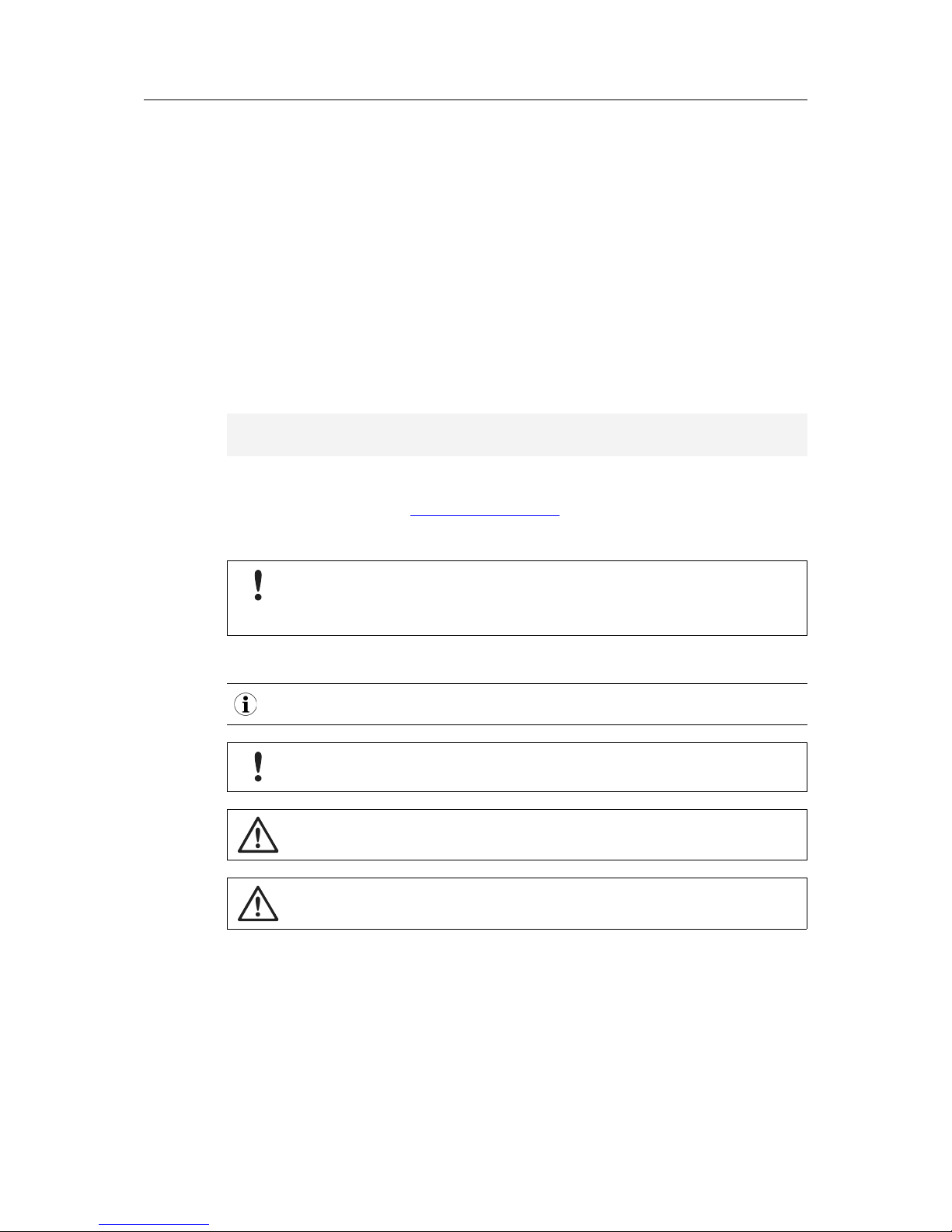
Safety advice is structured as follows:
Cause of the hazard!
Consequences of not taking remediate action.
How to avoid the hazard.
Safety signs and signalwords are used dependent on the level of the hazard.
This is additional information which may facilitate installation and/or operation.
This instruction must be followed to avoid a risk of reduced functionality and/or
damage to the equipment, or to avoid a network security risk.
Caution
This instruction must be followed to avoid a risk of personal injury.
WARNING
This instruction must be followed to avoid a risk of death or serious injury.
FRC-EP170 User Manual 4.01.0142.20000-EN 2.2
Page 7

Safety Instructions 5 (24)
2 Safety Instructions
2.1 Information on EMC
Risk of interference to radio and television if used in office or home environment!
The product is a class A device.
Use exclusively included accessories or HMS accessories that are intended for
use with the device.
Make sure shield of interface is connected with device plug and plug on other side.
Use exclusively shielded cables.
2.2 General Safety Notes
► Protect product from moisture and humidity.
► Protect product from too high or too low temperature (see Technical Data, p. 20).
► Protect product from fire.
► Do not throw, drop or try to bend the product.
► Do not paint the product.
► Do not modify or disassemble the product. Service must be carried out by HMS Industrial
Networks.
► Do not use modified products.
► Store products in dry and dust-free place.
2.3 Intended Use
This manual describes the external interfaces of the device, their functionality and pin allocation.
The device does not contain any application beside the operating system. Adding functionality
to the device is provided by the Automotive Configuration Tool (ACT) or the Software Development Kit. For further information refer to the corresponding manuals or online help.
The device is intended to be used in the office, stationary applications, test benches or test vehicles. Due to the missing E1 certification the usage in series cars is not allowed.
3 Scope of Delivery
Included in scope of delivery:
• FRC-EP170 production bundle:
– selected FRC-EP170 device variant
– selected optional accessories
– selected runtime licenses
• FRC-EP170 User Manual
• power supply cable
• USB cable
FRC-EP170 User Manual 4.01.0142.20000-EN 2.2
Page 8

Product Description 6 (24)
4 Product Description
The FRC-EP170 is a platform for the analysis, diagnostics and simulation of FlexRay, CAN,
CAN-FD, LIN and K-Line networks.
4.1 Features of the Basic Unit
• measurement and analysis platform
• up to 2 x FlexRay interfaces
• up to 4 x high-speed CAN interfaces
• up to 1 x low-speed CAN interface
• 1 x LIN interface
• 1 x K-Line interface
• 1 x RS232 interface
• up to 4 x digital inputs/outputs (5 V TTL Level)
• 1 x USB 2.0 device interface
• 1 x USB 2.0 host interface
• 1 x 10/100 Base-T Ethernet interface
• 2 x internal expansion slots
• 8 x LEDs, of which 7 are freely configurable
• real-time clock
• SDHC card slot
• up to 32 GByte SD card support for logging data
• 6-36 V DC power supply range with overvoltage and polarity protection
• operating temperature range -40 °C to +80 °C
4.2 Device Variants
The basic unit can be expanded with expansion cards via the two internal expansion slots.
Article number Description Additional features to basic unit
1.01.0142.00000 FRC-EP170
—
1.01.0142.00010 FRC-EP170 Plus 2 x CAN/CAN-FD interfaces
1.01.0142.00020 FRC-EP170 WLAN 1 x internal WLAN module
1.01.0142.00030 FRC-EP170 WLAN Plus 2 x CAN/CAN-FD interfaces
1 x internal WLAN module
Device variants are constantly improved and expanded!
Check current list on www.ixxat.com or contact IXXATsupport.
FRC-EP170 User Manual 4.01.0142.20000-EN 2.2
Page 9

Connectors 7 (24)
5 Connectors
5.1 User Interfaces (Front Side)
Fig. 1 FRC-EP170 front side
5.1.1 Power Connector (6-36 VDC)
The device is supplied with a DC voltage from 6 V to 36 V. The power supply input is protected
against overvoltage and against polarity reversal. The FRC-EP170 provides a 3-pin Binder
male panel mount connector, 710 series, 09-0977-00-03. The cable uses a 3-pin Binder female
cable connector, 710 series, 99-0976-10x-03.
Pin Allocation
Pin Signal Description
1 +VDC Power supply voltage +
2 - (GND) Power supply ground
3 KL15 Input to activate the Rescue Kernel
Individual Lines of Power Supply Cable
Pin Color Signal Description
1 White (ws/WT) VDC + Power supply +6 to +36 V with 4 mm red laboratory plug
2 Brown (br/BN) Ground - Power supply ground with 4 mm black laboratory plug
3 Green (gn/GN) KL15 Digital input with 4 mm green laboratory plug
► Use only the power supply cable that is included in the scope of delivery and available from
HMS Industrial Networks.
KL15 is equipped with a pull-up resistor to +VDC (approx. 80 kOhm). It is possible to leave
KL15 open, but for security reasons HMS Industrial Networks recommends, to connect VDC+
and KL15 inputs:
► For normal operation plug the green laboratory plug of the power cable into the red labora-
tory plug.
FRC-EP170 User Manual 4.01.0142.20000-EN 2.2
Page 10

Connectors 8 (24)
Function KL15 — Rescue Kernel
The KL15 input is checked when the device is switched on or booted and identifies whether the
system starts up normal or the rescue kernel is activated. If an active user configuration in the
flash storage obstructs external access to the device or if the operating system is corrupted, the
Rescue Kernel can be used to fix this situation.
► To force the device into Rescue Kernel, connect KL15 to ground (plug the green laboratory
plug in the black laboratory plug).
► Switch on the device.
➨ Device checks the KL15 input during start-up and starts the Rescue Kernel.
➨ LEDs 2-8 are flashing red.
► Connect IxAdmin via Ethernet.
► To repair the device see information in online help IxAdmin.
► Restart the device.
5.1.2 Ethernet Connector (LAN)
The standard Ethernet RJ45 connector is galvanically isolated from the other connectors.
5.1.3 USB Device Connector (USB-B)
The standard USB B type connector is used as a USB device interface to a PC. The USB connector is not galvanically isolated due to system constraints.
Damaged PC because of compensation current between test object and PC
through the USB connection.
Provide a grounded connection between the test object and the FRC-EP170,
before connecting the PC to the FRC-EP170 via USB.
► Provide a grounded connection between the test object and the FRC-EP170.
► Connect the PC via USB to the FRC-EP170.
5.1.4 USB Host Connector (USB-A)
The standard USB A type connector is used to connect USB devices to the FRC-EP170.
Damaged USB device because of compensation current between test object and
USB device through the USB connection.
When the FRC-EP170 is connected to test object, provide a grounded connection
between the test object and the FRC-EP170, before connecting a USB device to
the FRC-EP170 (for example a USB based analog input extension).
► When the FRC-EP170 is connected to test object, provide a grounded connection between
the test object and the FRC-EP170.
► Connect the USB device to the FRC-EP170.
► Use only FAT32 formatted USB sticks.
FRC-EP170 User Manual 4.01.0142.20000-EN 2.2
Page 11

Connectors 9 (24)
5.1.5 SD Card Slot (SD Card)
The SD card slot works with SD and SDHC cards.
Inserting the SD Card
► Push SD card in slot until the stop point.
► Make sure SD card is completely within the housing.
Removing the SD Card
► Push SD card into the slot until the stop point and release again.
➨ SD card holder pushes SD card out of the slot.
► Remove SD card by hand.
5.1.6 LED Array
LED 1 is the Power LED and indicates the device status. LEDs 2 to 8 are software-dependent
and indicate the communication status.
Power LED (LED 1)
LED state Description
Off No power supply (pin 1 power connector)
Red Boot mode, operating system is starting.
Green Boot mode is finished, applications are started or can be started.
LEDs 2-8
LEDs 2-8 can be configured via the software.
► For information about functionality see the specific software manual or online help.
If LEDs 2-8 are red flashing, the Rescue Kernel is executed.
► Connect IxAdmin via Ethernet.
► To repair the device see information in online help IxAdmin.
► Restart the device.
For more information see Function KL15 — Rescue Kernel, p. 8.
FRC-EP170 User Manual 4.01.0142.20000-EN 2.2
Page 12

Connectors 10 (24)
5.1.7 Remote/Debug Interface (REMOTE)
The function of the remote/debug interface depends on the executed application. The FRCEP170 provides a 7-pin Binder female panel mount connector, 710 series, 09-9478-00-07. The
cable uses a 7-pin Binder male cable connector, 710 series, 99-9475-10x-07.
The following application options are possible:
• If the software application in use supports debugging or control functions via RS232, the
cable provided by IXXATcan be used to connect to a PC.
• If the software application in use supports extended I/O functions, additional inputs and outputs can be used via the interface.
► For detailed information about the function of the interface see specific software manual or
online help.
Pin Allocation
Pin Signal Description
1 +5 V +5 V power supply for remote control, maximum current 20 mA
2 REM1/TX REMOTE1 digital output, RS232 TX transmission signal to PC
3 REM2/RX REMOTE2 digital input, RS232 RX receive signal from PC
4 REM3 REMOTE3 digital output
5 WKUP Wake-up option via remote
6 GND
—
7
—
Not used
FRC-EP170 User Manual 4.01.0142.20000-EN 2.2
Page 13

Connectors 11 (24)
5.2 Field Bus Interfaces (Back Side)
Fig. 2 FRC-EP170 back side
5.2.1 Connector X1
X1 is a D-Sub HD15 (High Density, 15-pin) male connector. CAN 1 high-speed and low-speed
cannot be used simultaneously because they are using the same CAN-Controller.
Pin Allocation
Signal Pin Description
CAN1 HS H 1 High-speed CAN 1 high signal
CAN1 HS L 6 High-speed CAN 1 low signal
CAN2 HS H 2 High-speed CAN 2 high signal
CAN2 HS L
7
High-speed CAN 2 low signal
GND 3 Common Ground
K-Line 4 K-Line signal
LIN 9 LIN signal
CAN5–FD H
5
Only with variant 10010/10030
CAN5–FD L 10 Only with variant 10010/10030
CAN1 LS L 11 Low-speed CAN 1 low signal
CAN1 LS H 12 Low-speed CAN 1 high signal
GND 13 Common ground
CAN6–FD H 14 Only with variant 10010/10030
VBAT (KL30) 15 Power supply
CAN6–FD L 8 Only with variant 10010/10030
CAN/CAN-FD/High-Speed/Low-Speed
The ISO 11898-3 low-speed CAN coupling is connected via two integrated termination resistors
of 2 kOhm each (RTH, RTL).
For ISO 11898-2 high-speed CAN and CAN-FD no bus termination resistor is integrated in the
device.
If a bus termination is required:
► Connect the bus termination to the cable and/or to the connector.
► Use suitable cable assemblies for the FRC-EP170, available from IXXAT.
FRC-EP170 User Manual 4.01.0142.20000-EN 2.2
Page 14

Connectors 12 (24)
LIN
The interface can be used either as Master or Slave. In Master mode a 1 kOhm resistor is used
on VBAT for LIN. In Slave mode the resistor is not connected.
K-Line
Only K-Line is available. The interface can be used either as Master or Slave. In Master mode a
1 kOhm resistor is used on VBAT for K-Line. In Slave mode the resistor is not connected.
VBAT
At VBAT the voltage of the power supply that is connected to +VDC of the power plug (see
Power Connector (6-36 VDC), p. 7) is provided, therefore the power supply can also be sup-
plied via the VBAT pin.
5.2.2 Connector X2
X2 is a D-Sub HD15 (High Density, 15-pin) female connector.
Pin Allocation
Signal Pin Description
FR1A BP 1 FlexRay channel 1 A, bus plus (only available on FlexRay variants)
FR1A BM 6 FlexRay channel 1 A, bus minus (only available on FlexRay variants)
FR1B/FR2A BP 2 Switchable via mutiplexer (only available on FlexRay variants)
FR1B/FR2A BM
7
Switchable via mutiplexer (only available on FlexRay variants)
GND 3 Common ground
CAN3 HS H 4 High-speed CAN 3 high signal
CAN3 HS L 9 High-speed CAN 3 low signal
CAN4 HS H
5
High-speed CAN 4 high signal
CAN4 HS L 10 High-speed CAN 4 low signal
DIG_IO1 11 Digital input/output, channel 1
DIG_IO2 12 Digital input/output, channel 2
GND 13 Common ground
DIG_IO3 14 Digital input/output, channel 3
DIG_IO4 15 Digital input/output, channel 4
—
8 Reserved
FlexRay
The FlexRay interfaces are only activated in the FlexRay device variant. In the CANonly device
variant the integrated interfaces are deactivated.
The two FlexRay interfaces have two independent FlexRay communication controllers. Both
controllers work on a shared FlexRay bus that is divided into channels A and B. Via software it
is possible to switch the channels to work on individual FlexRay buses. If the channels work on
individual buses, channel A is brought to the connector twice. No bus termination resistor is integrated into the device.
If a bus termination is required:
► Connect the bus termination to the cable and/or to the connector.
► Use suitable cable assemblies for the FRC-EP170, available from IXXAT.
FRC-EP170 User Manual 4.01.0142.20000-EN 2.2
Page 15

Connectors 13 (24)
CAN High-Speed
For ISO 11898-2 high-speed CAN and CAN-FD no bus termination resistor is integrated in the
device.
If a bus termination is required:
► Connect the bus termination to the cable and/or to the connector.
► Use suitable cable assemblies for the FRC-EP170, available from IXXAT.
Digital I/O
The direction of the digital I/Os can be selected via software. The status of a digital output can
be read back by the corresponding input.
When used as digital output:
• The maximum level of 5 V is reached when switched on.
• The output level voltage is dependent on the load. At the maximum load of 20 mA a voltage
level of 2.4 V is reached (TTL high-level).
• No protection for long lasting shortcuts or higher voltages connected is integrated.
When used as digital input:
• The voltage level for detecting a logical 1 is typically 2.4 V.
• Inputs are implemented by using Schmitt triggers, therefore threshold for the level transition is provided.
5.2.3 WiFi
Fig. 3 Antenna connector
WiFi functionality is provided at the RP-SMA female connector (1) at the back side of the device.
► Use exclusively the antenna, that is included in the scope of delivery (by reasons of radio
certification).
► Do not use any antenna extension cables (by reasons of radio certification).
► Screw included 2 dBi Dipole RP-SMA antenna into connector (1).
► To setup the WiFi, use the IxAdmin configuration tool.
► For further information see IxAdmin online help.
The internal WiFi is compliant with the IEEE 802.11b/g/n standard with data rates up to 150
Mbps. The 2.4 GHz frequency band is used with security/encryption according to WEP, WPA or
WPA2 standard. It supports access point, ad-hoc and client mode.
1
FRC-EP170 User Manual 4.01.0142.20000-EN 2.2
Page 16

Configuration Software 14 (24)
6 Configuration Software
The FRC-EP170 is a Linux platform that is able to work standalone without any connected PC.
For the standalone function a configuration is needed, that can be created and downloaded to
the device via a the PC based Automotive Configuration Tool (ACT).
The ACT tool is available on www.ixxat.com. The different functional range is determined by the
license via a USB dongle. For a detailed list of the functions see www.ixxat.com.
Available licence stages:
• freeware: no license dongle needed, all data logging functions available, receiving data is
possible
• gateway: all data logging functions available, data can also be transmitted from/to all fieldbuses, CAN2CAN gateways are possible
• full version: all functions are activated, creating residual bus simulations is possible
6.1 Installing the ACT Tool
► Download the ACT tool ZIP container from the support area on www.ixxat.com.
► Unpack the ZIP container in a user defined folder on the local drive.
► Execute the included installation file ACT-w.x.yyy.z-CM.exe.
➨ ACTsetup assistant is started.
► Follow instructions in ACT setup assistant.
► When ACT is installed, start ATC.
► For more information about the available functions of the license in use, select Help in the
main menu to open the online help.
6.2 Downloading a Basic Data Logging Configuration
As a basic configuration of the ACT tool, a data logger that writes all messages of the CAN busses 1 to 4 (500 kBit/s) in ASCII format to the SD card is provided.
► Power-up the device.
► Connect the device via USB to the PC.
► Start IxAdmin tool.
► In menu File select Connect New Device.
► Select device type in use in the list and select USB.
FRC-EP170 User Manual 4.01.0142.20000-EN 2.2
Page 17

Configuration Software 15 (24)
► To establish the connection to the device, click button OK.
Fig. 4 IxAdmin Device Connect example
FRC-EP170 User Manual 4.01.0142.20000-EN 2.2
Page 18

Configuration Software 16 (24)
► In menu Device select Add/Remove Application.
► Open the device configuration Basic_Logger.sdcfg in directory c:\Users\Public\Documents
\IXXAT\ACT\Projects\BasicLogger\DeviceConfig\.
Fig. 5 IxAdmin Application Download example
► To load the application to the device, click button Download/Start.
➨ Application is started.
For more information about the possibilities to change the CAN baudrate, to start and stop the
logger and to upload the logged data refer to the IxAdmin online help.
FRC-EP170 User Manual 4.01.0142.20000-EN 2.2
Page 19

Additional Components 17 (24)
7 Additional Components
HMS Industrial Networks offers the following additional components.
Connector Description Article number
POWER Cable with 3 banana plugs, 2.0 m 1.04.0089.00001
REMOTE Debugging cable with D-Sub 9 for RS232 for connection to PC 1.04.0089.00301
X1 Breakout cable with D-Sub 15 HD female, 1.5 m (see Breakout Cable for
X1 and X2, p. 19)
1.04.0089.00100
X1 Breakout cable with D-Sub 15 HD female, 0.5 m (see Breakout Cable for
X1 and X2, p. 19)
1.04.0089.00103
X1 Breakout box with D-Sub 15 HD female and 5 x D-Sub 9, 0.5 m (see Break-
out Box for X1 and X2, p. 18)
1.01.0081.00200
X2 FlexRay-1A cable with D-Sub 15 HD and 1 x D-Sub 9, 1.5 m (see FlexRay-
1A Cable, p. 17)
1.04.0089.00102
X2 D-Sub 15 HD male gender changer to adapt X1 accessories and FlexRay-
1A cable to X2
1.04.0075.04000
7.1 FlexRay-1A Cable
HMS Industrial Networks offers for the FlexRay device variant a ready-made cable to provide
the FlexRay-1A interface of the connector X2 at a standard D-Sub 9 connector. The FlexRay
termination resistor is integrated in the cable in the connector housing at the device side. To use
the FlexRay-1A cable with connector X1, use the gender changer that is offered by HMS Industrial Networks.
Fig. 6 FlexRay-1A cable
female
female
Schematic Circuit Diagram
green
blue
yellow
FRC-EP170 User Manual 4.01.0142.20000-EN 2.2
Page 20

Additional Components 18 (24)
7.2 Breakout Box for X1 and X2
Depending on the device variant several interfaces are connected to the connectors X1 and X2.
HMS Industrial Networks offers a breakout box to provide each of the interfaces on one dedicated connector. To use the breakout box with connector X1, use the gender changer that is offered by HMS Industrial Networks.
Fig. 7 Breakout box
Pin Allocation Breakout Box for X2
Connector Variant Pin Allocation D-Sub 9
Pin Signal
Y1 FlexRay-1A 2 FR BM or CAN L
7
FR BP or CAN H
3 GND
6 GND
Y2 FlexRay-1B/2A See Y1
Y3 CAN 3 See Y1
Y4 CAN 4 See Y1
Y5 Digital-I/O 1, 2, 4, 5 DIG_IO 1..4
3 GND
Pin Allocation Breakout Box for X1 (with Gender Changer)
Connector Variant Pin Allocation D-Sub 9
Pin Signal
Y1 CAN 1 2 CAN L
7
CAN H
3 GND
6 GND
Y2 CAN 2 See Y1
Y3 Not used
— —
Y4 CAN 5 See Y1
Y5 CAN 6 3 GND
4 CAN FD H
9 CAN FD L
FRC-EP170 User Manual 4.01.0142.20000-EN 2.2
Page 21

Additional Components 19 (24)
7.3 Breakout Cable for X1 and X2
Depending on the device variant several interfaces are connected to the connectors X1 and X2.
HMS Industrial Networks offers breakout cables in different lengths to allow the creation of specific adapters. To use the breakout cable with connector X1, use the gender changer that is offered by HMS Industrial Networks.
Fig. 8 Breakout cable
Pin Color Pin Color
1 WT 9 PK
2 GN 10 RD
3 SW 11 GY-PK
4 GY 12 RD-BU
5 BU 13 WT-YE
6 BN 14 WH-GN
7 YE 15 BN-GN
8 VT
open ends
shield
stripping off the insulation
tinning
female
FRC-EP170 User Manual 4.01.0142.20000-EN 2.2
Page 22

Technical Data 20 (24)
8 Technical Data
Basic Unit
Dimensions (L x W x H) 142 x 113 x 40 mm
Weight Approx. 390 g
Operating temperature -40 °C to +80 °C
Storage temperature -40 °C to +85 °C
Power supply 6-36 V DC
Current consumption Typ. 320 mA at 12 V
Housing material Aluminium
Relative humidity 10-95 %, non-condensing
Host system Power PC, 256 MByte RAM, 256 MByte Flash
Ethernet 10/100 MBit/s, RJ45
USB 2.0 high-speed device, USB-B
2.0 high-speed device, USB-A
FlexRay communication controller 2 x Freescale MFR 4310
FlexRay transceiver NXP TJA1080
CAN transceiver CAN-FD Texas Instruments TCAN334GDCN
CAN transceiver high-speed Texas Instruments SN65HVD251
CAN transceiver low-speed NXP TJA1054T
CAN bus termination resistor High-speed/CAN-FD: none
Low-speed: RTH=RTL=2 kΩ
LIN transceiver NXP TJA1020
K-LINE transceiver Vishay SI9243AEY
System startup time < 5 sec from power-on
FRC-EP170 User Manual 4.01.0142.20000-EN 2.2
Page 23

Support/Return Hardware 21 (24)
9 Support/Return Hardware
Observe the following information in the support area on www.ixxat.com:
• information about products
• FAQ lists
• installation notes
• updated product versions
• updates
9.1 Support
► For problems or support with the product request support at www.ixxat.com/support.
► If required use support phone contacts on www.ixxat.com.
9.2 Return Hardware
► Fill in the form for warranty claims and repair on www.ixxat.com.
► Print out the Product Return Number (PRN resp. RMA).
► Pack product in a physically- and ESD-safe way, use original packaging if possible.
► Enclose PRN number.
► Observe further notes on www.ixxat.com.
► Return hardware.
10 Disposal
► Dispose of product according to national laws and regulations.
► Observe further notes about disposal of products on www.ixxat.com.
FRC-EP170 User Manual 4.01.0142.20000-EN 2.2
Page 24

This page intentionally left blank
Page 25

Appendix A: Regulatory Compliance 23 (24)
A Regulatory Compliance
A.1 EMC Compliance (CE)
The product is in compliance with the Electromagnetic Compatibility Directive. More information
and the Declaration of Conformity is found at www.ixxat.com.
A.2 Disposal and recycling
You must dispose of this product properly according to local laws and regulations. Because this
product contains electronic components, it must be disposed of separately from household
waste. When this product reaches its end of life, contact local authorities to learn about disposal
and recycling options, or simply drop it off at your local HMS office or return it to HMS.
For more information, see www.hms-networks.com.
FRC-EP170 User Manual 4.01.0142.20000-EN 2.2
Page 26

last page
© 2018 HMS Industrial Networks AB
Box 4126
300 04 Halmstad, Sweden
info@hms.se 4.01.0142.20000-EN 2.2.7979 / 2018-03-27
 Loading...