

IXXAT CME/PN Hardware Manual
Hardware Manual
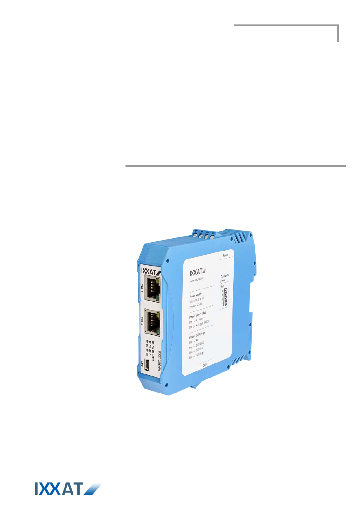
IXXAT CME/PN
CANopen-PROFINET Gateway

E-Mail: info@ix x at. d e
Support
www.ixxat.com
Copyright
All
rights are reserved.
Registered trademarks
bject to the conditions of each valid
protected by trademark law.
Document number: 4.01.0261.20000
Version: 1.0
IXXAT Automation GmbH
Leibnizstr. 15
88250 Weingarten
Germany
Tel.: +49 751 56146-0
Fax: +49 751 56146-29
Internet: www.ixxat.de
In case of unsolvable problems with this product or other IXXAT products
please contact IXXAT in written form:
Fax: +49 751 56146-29
E-Mail: support@ixxat.de
Further international support contacts can be found on our webpage
Duplication (copying , printi ng, m icrof ilm or other form s) and t he elec tro nic
distribution of this document is only allowed with explicit permission of
IXXAT Automation Gm bH. IXXAT Autom ation Gm bH reserves the right to
change technical data without pri or announcement. The gen eral b usines s
conditions and the regulations of the license agreement do apply.
All trademarks mentioned in this document and where applicable third
party registered are absolutely su
label right and the rights of particular registered proprietor. The absence
of identification of a tradem ark does not automat ically mean that it is not

Content
1 Introduction .................................................................................... 5
1.1 Overview .................................................................................. 5
1.2 Features ................................................................................... 5
2 Installation ...................................................................................... 6
2.1 Software installation ............................................................... 6
2.2 Hardware installation .............................................................. 6
3 Connections and displays ............................................................. 7
3.1 Connection pinout .................................................................. 7
3.1.1 Power plug ............................................................................... 7
3.1.2 Ethernet connectors ................................................................. 8
3.1.3 CAN bus connection ................................................................ 8
3.2 Displays ................................................................................... 9
3.2.1 Power LED (ON) .................................................................... 10
3.2.2 PROFINET Status LEDs (S1/S2) ........................................... 10
3.2.3 Host Status LED (HOST) ....................................................... 11
3.2.4 CAN RUN LED (C1) ............................................................... 11
3.2.5 CAN ERROR LED (C2) ......................................................... 12
3.2.6 Link Status LEDs.................................................................... 12
4 Appendix ...................................................................................... 13
4.1 Support .................................................................................. 13
4.2 Returning hardware .............................................................. 13
4.3 FCC-Konformität ................................................................... 13
4.4 Disposing of old equipment ................................................. 13
4.5 Information on EMC .............................................................. 14
4.6 Technical data ....................................................................... 15
4.7 EC Declaration of Conformi ty .............................................. 16
Copyright IXXAT Automation GmbH
3
IXXAT CME/PN Manual, Version 1.0


Introduction
1 Introduction
1.1 Overview
In the CANopen-PROFINET Gate way IXXAT CME/PN , you ha ve purchased a
high-quality electronic compon ent that has been developed an d manufactured
according to the latest technological state of the art.
1.2 Features
Input voltage range 9 - 32 V DC
Power consumption 2.5 W
Temperature range -20 °C up to +70 °C
2 x 100 MBit/s Ethernet using RJ45 connectors
Built-in 2-port switch
Galvanically isolated CAN bus interface as defined in ISO11898-2
CAN connections using screw terminals
Housing for top hat rail mounting
USB configuration interface using Mini-USB
Copyright IXXAT Automation GmbH
5
IXXAT CME/PN-Manual, Version 1.0
 Loading...