

IXXAT CANlink II Hardware Manual
Hardware Manual
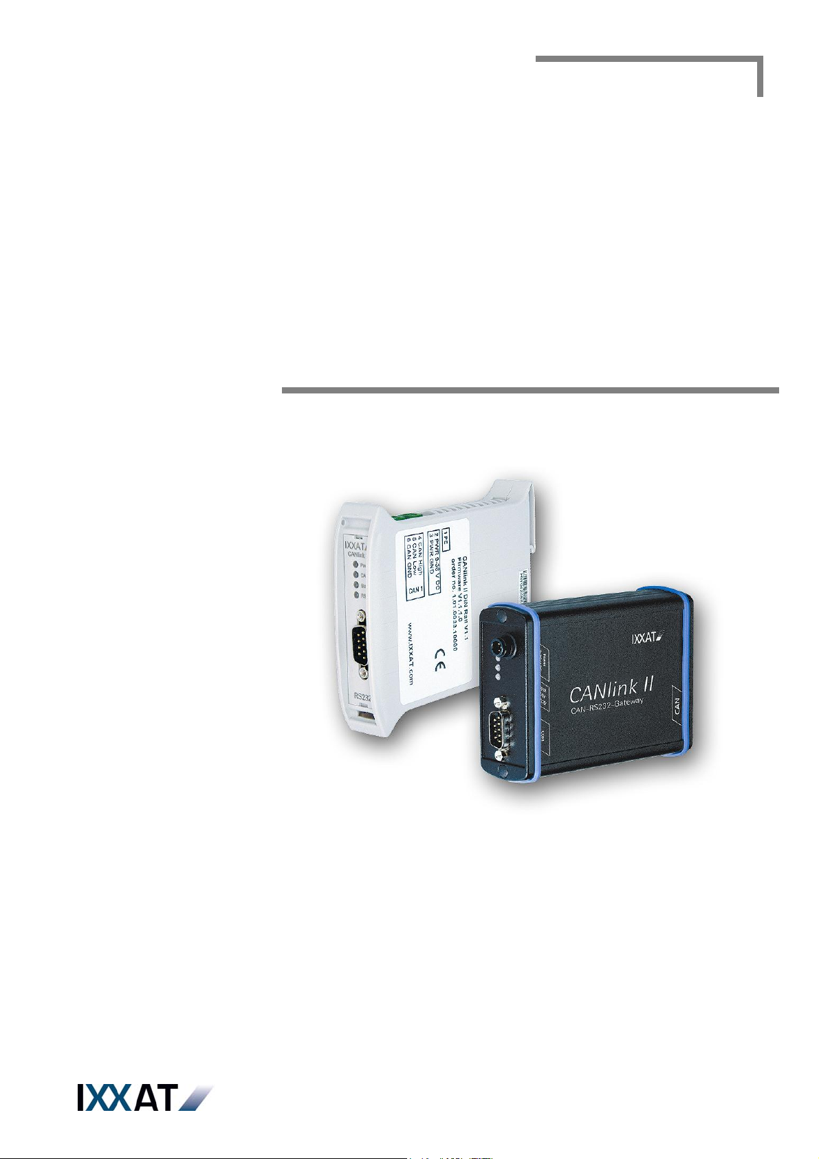
CANlink II
RS232-CAN Converter
The expert for industrial and automotive communication

IXXAT
Headquarter US Sales Office
IXXAT Automation GmbH IXXAT Inc.
Leibnizstr. 15 120 Bedford Center Road
D-88250 Weingarten USA-Bedford, NH 03110
Tel.: +49 (0)7 51 / 5 61 46-0 Phone: +1-603-471-0800
Fax: +49 (0)7 51 / 5 61 46-29 Fax: +1-603-471-0880
Internet: www.ixxat.de Internet: www.ixxat.com
e-Mail: info@ixxat.de e-Mail: sales@ixxat.com
Support
In case of unsolvable problems with this product or other IXXAT products
please contact IXXAT in written form by:
Fax: +49 (0)7 51 / 5 61 46-29
e-Mail: support@ixxat.de
Copyright
Duplication (copying, printing, microfilm or other forms) and the electronic
distribution of this document is only allowed with explicit permission of
IXXAT Automation GmbH. IXXAT Automation GmbH reserves the right to
change technical data without prior announcement. The general business
conditions and the regulations of the license agreement do apply. All rights
are reserved.
Handbuchnummer: 4.01.0032.20000
Version: 1.3

Contents
1 Lead-in ........................................................................................7
1.1 Overview ............................................................................. 7
1.2 Features............................................................................... 8
1.3 Versions............................................................................... 8
1.4 Block diagram ..................................................................... 9
1.5 Support ............................................................................. 10
1.6 Returning hardware.......................................................... 10
2 Aluminum housing version.......................................................11
2.1 Connector allocation......................................................... 11
2.1.1 Power supply (X1)...................................................................11
2.1.2 Serial interface RS232 (X2) ......................................................12
2.1.3 CAN (X3) ................................................................................12
2.2 Ground connections ......................................................... 13
3 Industrial DIN rail version .........................................................14
3.1 Connector allocation......................................................... 14
3.1.1 Power supply (X1)...................................................................15
3.1.2 Serial interface RS232 (X2) ......................................................15
3.1.3 CAN (X3) ................................................................................16
3.2 Ground connections ......................................................... 16
4 Description of functions ...........................................................17
4.1 Introduction ...................................................................... 17
4.2 RS232-CAN gateway ......................................................... 17
4.3 RS232-CANopen gateway ................................................. 18
4.4 Data structure of the configuration files.......................... 22
4.4.1 General settings [General] .......................................................23
4.4.1.1 Product name (ProductName)....................................23
4.4.1.2 Version number (TemplateVersion) ............................23
4.4.1.3 Operation mode (OperationMode) ............................23
4.4.1.4 Timeout ....................................................................23
4.4.2 User settings [User] .................................................................23
4.4.2.1 Configuration name (ConfigAlias) ..............................23
4.4.3 RS232 settings [RS232] ...........................................................23
4.4.3.1 Baudrate (RS232baudrate).........................................23
4.4.3.2 Number of databits (Databits) ...................................24
Copyright IXXAT Automation GmbH
3
CANlink II - Manual, V1.3

Contents
4.4.3.3 Parity (Parity)............................................................. 24
4.4.3.4 Flow control (Handshake).......................................... 24
4.4.4 CANlink settings [CANlink] ......................................................24
4.4.4.1 Baudrate (CANbaudrate) ...........................................24
4.4.4.2 Frame format (FrameFormat)..................................... 24
4.4.4.3 Send identifier (SendID)............................................. 25
4.4.4.4 Receive identifier (ReceiveID)...................................... 25
4.4.5 COPlink settings [COPlink]....................................................... 25
4.4.5.1 Baudrate (CANopenBaudrate).................................... 25
4.4.5.2 CANopen node number (CANopenNode)...................25
4.4.5.3 Heartbeat time (HBTime)........................................... 25
4.4.5.4 Receive PDO (RxPDO) ................................................25
4.4.5.5 Receive PDO type (RxPDOtype)...................................26
4.4.5.6 Transmit-PDO (TxPDO) ..............................................26
4.4.5.7 Transmit-PDO type (TxPDOtype).................................26
4.4.5.8 Byte stream flow control (ByteStreamExtension)........26
4.5 Default configuration ........................................................27
5 Download tool..........................................................................29
5.1 Configuration with Windows console program................29
5.1.1 Creating a configuration file ................................................... 30
5.1.2 Download of a configuration ..................................................30
5.1.3 Displaying the current configuration .......................................31
5.1.4 Saving the current configuration ............................................. 32
6 Configuration tool....................................................................33
6.1 Configuration with Windows application .........................33
6.1.1 Default configuration ............................................................. 33
6.1.2 Loading and saving a configuration ........................................34
6.1.3 Setting up a connection..........................................................34
6.1.4 Reading the current configuration........................................... 36
6.1.5 Downloading a configuration .................................................37
6.1.6 Disconnecting......................................................................... 37
6.2 Configuration cable ...........................................................37
7 Displays.....................................................................................38
7.1 Normal mode .....................................................................38
7.1.1 Power LED.............................................................................. 38
Copyright IXXAT Automation GmbH
4
CANlink II - Manual, V1.3

Contents
7.1.2 CAN LED.................................................................................38
7.1.3 COP LED .................................................................................38
7.1.4 RS232 LED..............................................................................38
7.2 Configuration mode ......................................................... 39
7.3 Error state ......................................................................... 39
8 Notes on EMC ...........................................................................40
8.1 Aluminum version............................................................. 40
8.2 Industrial DIN-rail version – shield concept ...................... 40
Appendix..........................................................................................41
Technical specifications............................................................ 41
Sources of data sheets............................................................. 41
EC conformity declaration....................................................... 42
Copyright IXXAT Automation GmbH
5
CANlink II - Manual, V1.3


Lead-in
1 Lead-in
1.1 Overview
Congratulations on your purchase of the IXXAT CANlink II, a high-quality electronic component developed and manufactured according to the latest technological standards.
This manual is intended to familiarize you with your CANlink II. Please read this
manual before initial startup.
The CANlink II enables devices with only one serial port a simple, configurable
access to CAN and CANopen networks. CANlink II provides two operation modes
for this purpose.
In the CAN operation mode (CANlink), received CAN data are transmitted transparently to the RS232 interface. Data received via RS232 are mapped into CAN
telegrams and transmitted. One configurable identifier each is available for
transmission and reception.
In the CANopen operation mode (COPlink), the CANlink operates as a CANopen
node, where the serial data are stored as a byte stream object in the manufacturer-specific object dictionary range.
The supported CANopen features are:
• 1 server SDO expedited, non-expedited, no CRC check
• 1 TX PDO static mapping
• 1 RX PDO static mapping
• Emergency message
• Heartbeat producer
• NMT slave
The communication interfaces and operation modes are configured by means of
a configuration file, which is saved on the device via a loading program.
The CANlink II is available in two housing versions, a plastic housing for DIN rail
mounting or as a desktop device in a robust aluminum housing.
Copyright IXXAT Automation GmbH
7
CANlink II - Manual, V1.3

Lead-in
1.2 Features
• Supply voltage 9-36 V
• CAN bus interface in accordance with ISO 11898-2, optional galvanic isolation
• Serial interface (RS232) up to 115 kbaud
• Fujitsu 16 bit microcontroller
• Two housing versions available
1.3 Versions
The following versions of the CANlink II are available:
Housing
Supply voltage
Bus interface
Galvanic isolation
Industrial
DIN rail
Industrial
aluminum
Plastic Aluminum
9 V – 36 V 9 V – 36 V
high speed
(ISO 11898-2)
high speed
(ISO 11898-2)
optional optional
Copyright IXXAT Automation GmbH
8
CANlink II - Manual, V1.3
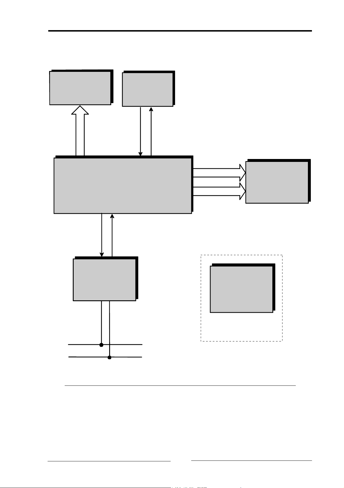
1.4 Block diagram
Lead-in
Full RS232
transceiver
optional RS485
s
e
n
i
L
2
3
2
S
R
Microcontroller
internal
RS232
Adapter
RxD
MB90F543
CAN
TxD
D 0..15
A 0..17
Optional
Data
Memory
CAN Bus
Interface
High Speed
CAN High
CAN Low
CAN Bus
In dustrial
Range
(9V -36 V )
Power Supply
Fig. 1-1: Block diagram CANlink II
Copyright IXXAT Automation GmbH
9
CANlink II - Manual, V1.3

Lead-in
1.5 Support
For more information on our products, FAQ lists and installation tips, please refer
to the support section of our website (http://www.ixxat.de), which also contains
information on current product versions and available updates.
If you have any further questions after studying the information on our website
and the manuals, please contact our support department. The support section on
our website contains the relevant forms for your support request. In order to facilitate our support work and enable a fast response, please provide precise information on the individual points and describe your question or problem in detail.
If you would prefer to contact our support department by phone, please also
send a support request via our website first, so that our support department has
the relevant information available.
1.6 Returning hardware
If it is necessary to return hardware to us, please download the relevant RMA
form from our website and follow the instructions on this form.
In the case of repairs, please also describe the problem or fault in detail on the
RMA form. This will enable us to carry out the repair quickly.
Copyright IXXAT Automation GmbH
10
CANlink II - Manual, V1.3
Aluminum housing version
2 Aluminum housing version
2.1 Connector allocation
X1
LED
X2 X3
Fig. 2-1: Connector arrangement aluminum version
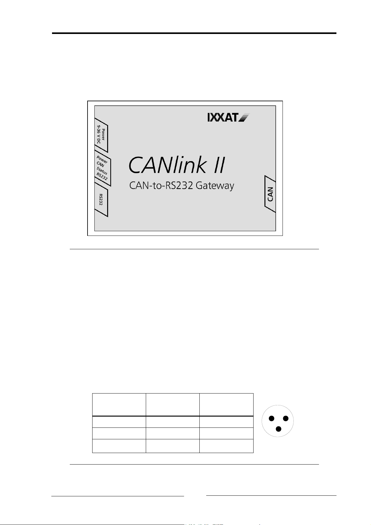
2.1.1 Power supply (X1)
The device is supplied with direct voltage of 9 V - 36 V. A pre-fabricated cable for
power supply is included in the scope of delivery. The connection allocation is
shown in Table 2-1.
The CANlink II is protected against polarity reversal, under-voltage and overvoltage. In the event of polarity reversal or under-voltage, it is switched off, with
over-voltage an internal fuse is triggered.
Pin no.
X1
1 PWR (+) White
2 GND (-) Brown
3 Shield Shield
Table 2-1: Pin allocation Power
Copyright IXXAT Automation GmbH
Signal Lead color
123
1
11
CANlink II - Manual, V1.3
Aluminum housing version
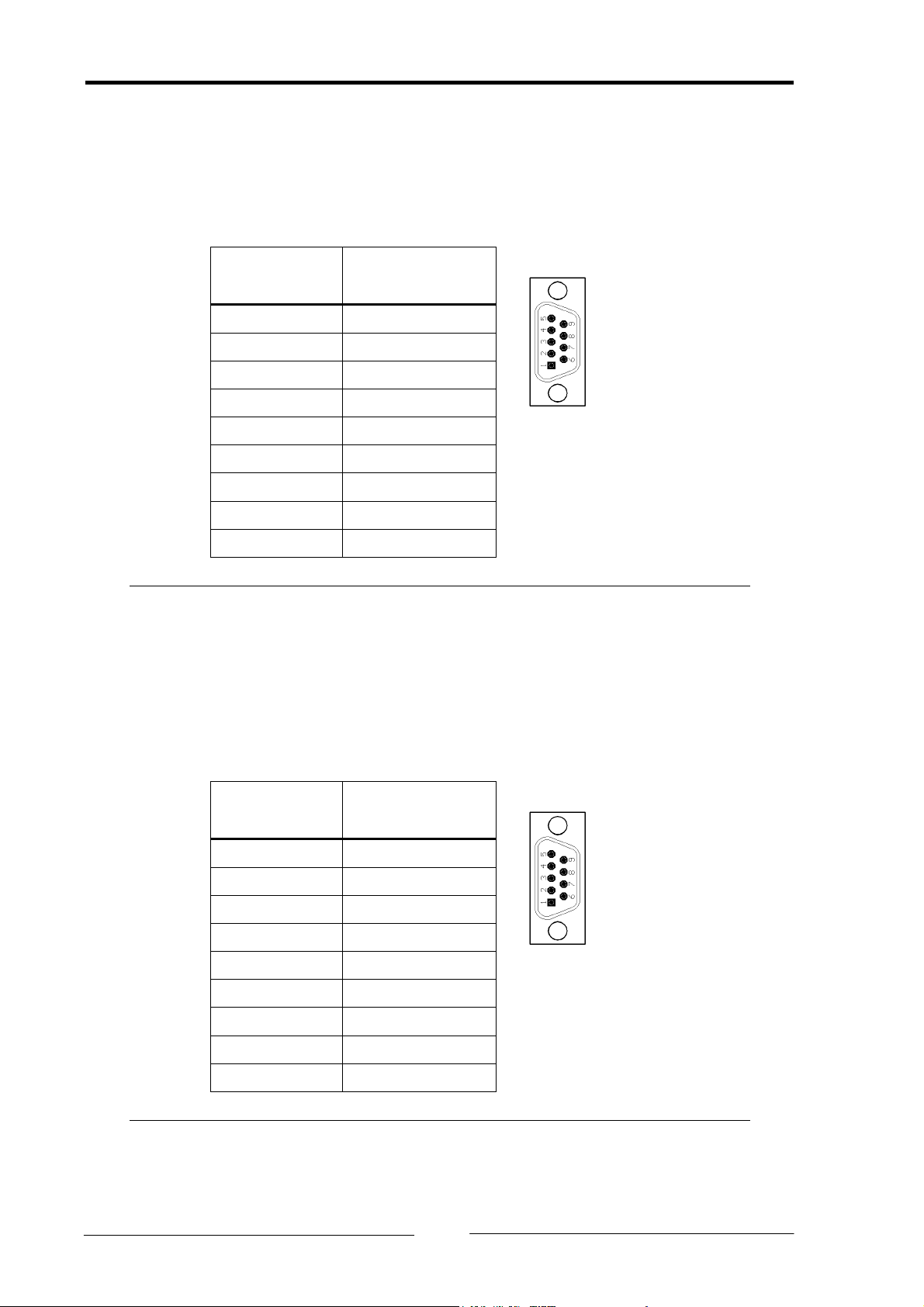
2.1.2 Serial interface RS232 (X2)
The signals of the serial port are connected to the 9-pin Sub-D connector X2 (see
table 2-2). The pin allocation complies with the standard for DTE devices. For
configuration of the device with a PC, you require a laplink cable.
Pin no.
Signal
X2
1 DCD
2 RX
3 TX
4 DTR
5 GND
6 DSR
7 RTS
8 CTS
9 RI
Table 2-2: Pin allocation RS232
2.1.3 CAN (X3)
CAN is available on connector X3 with a bus interface according to ISO 11898-2.
The signals of the bus interface are connected to the 9-pin Sub-D connector X3
(see Table 2-3). The pin allocation complies with the standard CiA DS102
Pin no.
Signal
X3, X4
1 2 CAN Low
3 GND
4 5 6 7 CAN High
8 9 -
Table 2-3: Pin allocation CAN
Copyright IXXAT Automation GmbH
12
CANlink II - Manual, V1.3

Aluminum housing version
2.2 Ground connections
In the galvanically isolated version, the GND of CAN (X3) is isolated from the rest
of the circuit, the GND of the serial port (X2) is connected to the GND of the
power supply (X1).
In the version without galvanic isolation, all GND connections (X1, X2, X3) are
connected with each other.
The shield connections of CAN (X3), serial port (X2) and power supply (X1) are
connected with each other both in the version with and in the version without
galvanic isolation.
Copyright IXXAT Automation GmbH
13
CANlink II - Manual, V1.3
 Loading...