

IXXAT CANio 250 Quick Start Manual
CANio 250
I/O-to-CAN Gateway
English
Quickstart Manual

HMS Technology Center Ravensburg GmbH
Helmut-Vetter-Straße 2
D-88213 Ravensburg
Germany
Tel.: +49 751 56146-0
Fax: +49 751 56146-29
Internet: www.hms-networks.com
E-Mail: info-ravensburg@hms-networks.com
Support
In case of unsolvable problems with this product or other HMS products
please fill in support form in the support are on www.ixxat.com.
Further international support contacts can be found on our webpage
www.ixxat.com
Copyright
Duplication (copying, printing, microfilm or other forms) and the electronic
distribution of this document is only allowed with explicit permission of
HMS Technology Center Ravensburg GmbH. HMS Technology Center
Ravensburg GmbH reserves the right to change technical data without
prior announcement. The general business conditions and the regulations
of the license agreement do apply. All rights are reserved.
Registered Trademarks
All trademarks mentioned in this document and where applicable third
party registered are absolutely subject to the conditions of each valid
label right and the rights of particular registered proprietor. The absence
of identification of a trademark does not automatically mean that it is not
protected by trademark law.
Document number: 4.01.0099.20000
Version: 1.2

Content
3 CANio 250 Quickstart Manual, version 1.2
1 General information ....................................................................... 5
1.1 Highlights ................................................................................ 5
1.2 Designs and device variants ................................................. 5
2 Connector assignments ................................................................. 6
2.1 Connector (X1) power supply 6-32 V DC .............................. 6
2.2 Connector (X2) CAN ............................................................... 7
2.3 Connector (X3, X4) digital A/B ............................................... 7
3 LED displays ................................................................................... 8
3.1 PWR - LED .............................................................................. 8
3.2 CAN - LED ............................................................................... 8
3.3 USR 1/2 - LED ......................................................................... 8
4 Description of functions ................................................................ 8
4.1 Introduction ............................................................................ 8
4.2 Galvanic isolation .................................................................. 8
4.3 Digital outputs ........................................................................ 8
4.4 Additional digital input on connector (X1) ........................... 9
4.5 Power supply PWR(+) ............................................................ 9
5 Software ........................................................................................ 10
5.1 CANio 250 as a CAN module ................................................ 11
5.1.1 CAN Identifier ......................................................................... 11
5.1.2 CAN baudrate ........................................................................ 11
5.1.3 Node number ......................................................................... 11
5.1.4 Digital outputs ........................................................................ 11
5.1.5 Digital inputs ........................................................................... 13
5.1.6 Digital inputs: edge events ..................................................... 14
5.1.7 Value of the power supply PWR(+) ........................................ 15
5.1.8 Heartbeat message ................................................................ 16
5.1.9 Emergency messages ............................................................ 17
5.1.10 Error management ................................................................ 18
5.1.11 Factory settings .................................................................... 19
5.1.12 Reserved CAN identifiers ..................................................... 19
5.1.13 Steering the state machine of the CANio 250 ...................... 20

Content
4 CANio 250 Quickstart Manual, version 1.2
6 General ......................................................................................... 23
6.1 Support ................................................................................. 23
6.2 Returning hardware.............................................................. 23
6.3 Note on disposal of used devices ....................................... 23
6.4 Note on EMC ......................................................................... 24
6.5 FCC Compliance ................................................................... 24
6.6 EC DECLARATION OF CONFORMITY ................................. 25

General information
5 CANio 250 Quickstart Manual, version 1.2
1 General information
The CANio 250 is a universal interface for analog and digital signals.
This manual is intended to help you to learn more about the CANio 250.
Please read this manual before using the CANio 250 for the first time. Therefore it is restricted to the essential topics. For further details – mainly with respect to the application software – the corresponding manuals are provided
online.
1.1 Highlights
Power supply 6 - 32 V DC
Power consumption 1 Watt (without load connected to the outputs)
CAN bus connection according to ISO 11898-2 with galvanic isolation
Communication as CAN node or CANopen device
Up to 16 digital inputs (5V CMOS level)
Up to 16 digital outputs (5V CMOS level, max. 30mA)
Monitoring of the power supply
Additional digital input on power supply connector
2 LEDs (both two-colored) controllable via software
1 LED for the CAN bus status
1 LED for the power supply
Robust aluminum housing
Temperature range -40 °C to 70 °C
1.2 Designs and device variants
The CANio 250 is available in the following variants:
Order number
Designs and device versions
1.01.0099.00000
CANio 250 Standard
Connector assignments
6 CANio 250 Quickstart Manual, version 1.2
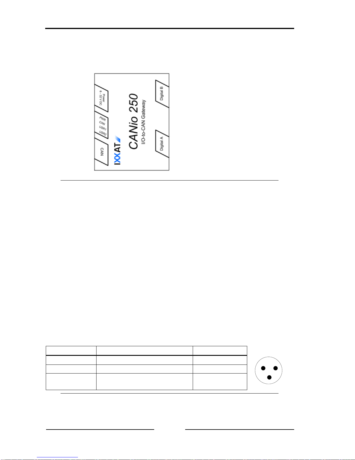
2 Connector assignments
X1 X3
LED
X2 X4
Figure 2-1: Connector assignments
2.1 Connector (X1) power supply 6-32 V DC
The CANio 250 is supplied with DC voltage of 6 V – 32 V The scope of supply
includes a made-up cable for power supply. The terminal assignment is given
in table 2-1.
The type of connector is: Binder cable socket 99-0976-100-03
The CANio 250 is protected against reverse polarity, undervoltage and overvoltage. It is switched off in the case of reverse polarity or undervoltage. The
CANio survives overvoltage up to 60 V and load dump undamaged. In the
event of voltages above this, an internal fuse may be tripped. If the internal
fuse is tripped, the CANio 250 is no longer operational and must be returned to
for repair.
The additional digital input is also connected on this connector.
Pin no. X1
Signal
Wire color
1
123
1
PWR (+)
white
2
GND (-)
brown
3
Additional digital input on power supply connector
Shield
Table 2-1: Pin assignment power supply
Connector assignments
7 CANio 250 Quickstart Manual, version 1.2
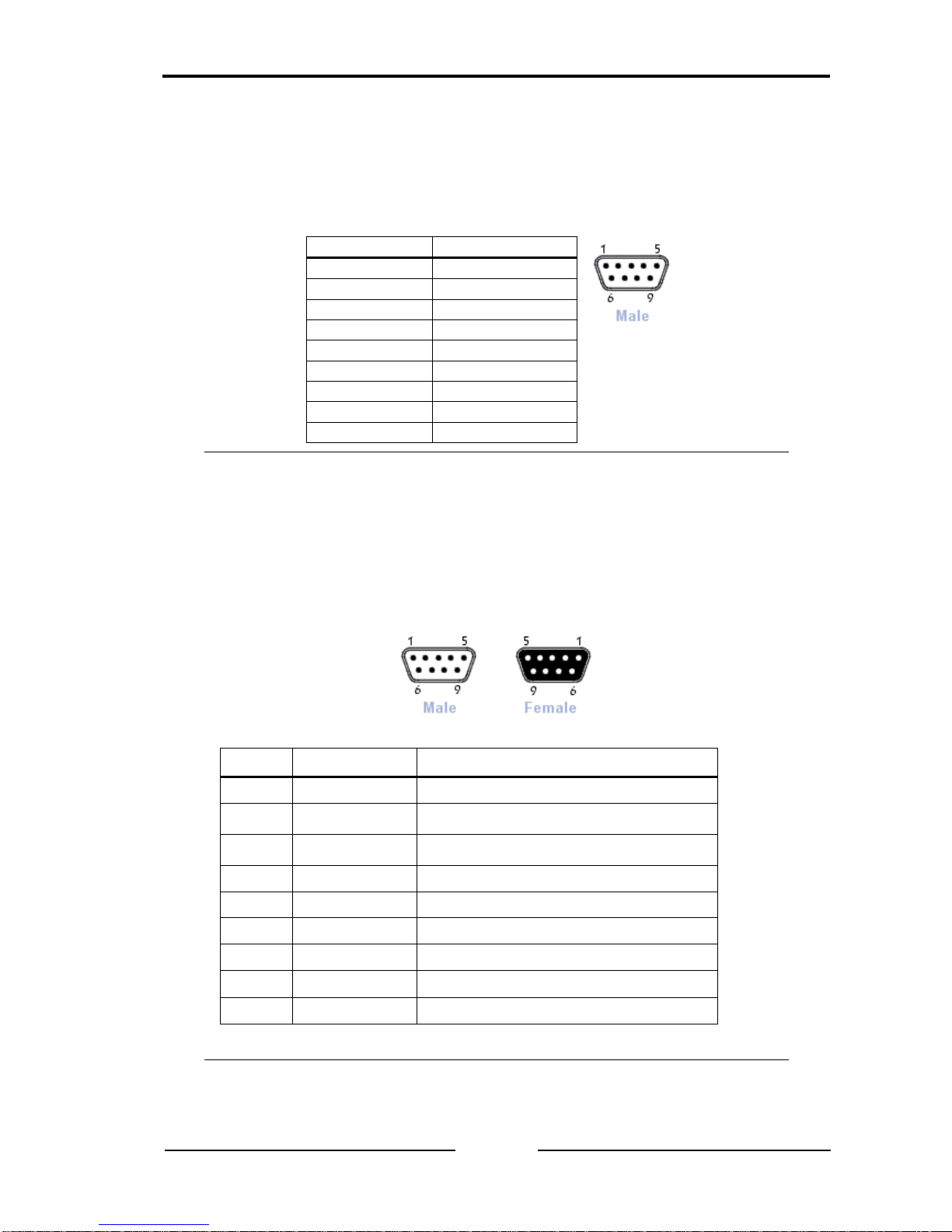
2.2 Connector (X2) CAN
CAN is available on connector X2 with a bus connection according to ISO
11898-2. The signals of the bus connection are available on the 9-pin D-Sub
connector (pins, male) (see table 2-2).
Pin Nr.
Signal
1 - 2
CAN Low
3
GND_GND
4 - 5
-
6
-
7
CAN High
8
Reserviert
9
-
Table 2-2: Pin assignment CAN connector D-Sub 9
2.3 Connector (X3, X4) digital A/B
The digital signals are available on connector X3/4. Connector X3 is designed
as a 9-pin D-Sub (socket, female), connector X4 is designed as a 9-pin D-Sub
(pins, male) (see table 2-3).
The functions of the digital inputs and outputs are described in chapters 4.3.
Pin Nr.
Signal
Beschreibung
1
DIG_1
Digital In/Out 1
2
DIG_2
Digital In/Out 2
3
DIG_3
Digital In/Out 3
4
DIG_4
Digital In/Out 4
5
DIG_5
Digital In/Out 5
6
DIG_6
Digital In/Out 6
7
DIG_7
Digital In/Out 7
8
DIG_8
Digital In/Out 8
9
GND
Ground
Table 2-3: Pin assignment digital interface connector D-Sub

LED displays
8 CANio 250 Quickstart Manual, version 1.2
3 LED displays
The CANio 250 has four two-colored LEDs (see Figure 2-1). The LEDs react
as follows according to the operating mode of the CANio 250.
3.1 PWR - LED
The Power-LED (PWR) is lit green when the CANio 250 is connected to the
power supply. The Power-LED (PWR) is lit red when the power supply is connected with reverse polarity.
3.2 CAN - LED
The CAN-LED displays the status of the CANopen State Machine (green) and
the error status. In the 'CAN BUS OFF' status, no more communication is possible and the CAN - LED is permanently lit red.
3.3 USR 1/2 - LED
The User-LEDs (USR 1/2-LED) which can be freely programmed by the user,
can be switched via CAN messages. More information is given in chapters
5.1.4.
4 Description of functions
4.1 Introduction
The CANio 250 allows monitoring or setting of digital signals via a CAN network.
4.2 Galvanic isolation
In the case of galvanic isolation, the ground of CAN (GND_CAN) is isolated
from the rest of the circuit.
The ground of the power supply [GND (-)] and of the digital and analog interfaces are connected to each other.
4.3 Digital outputs
In total, the CANio 250 supports up to 16, 5V CMOS compatible, digital in/outputs. The digital outputs can be switched or monitored with CAN messages. More information is given in chapters 5.1.4.
The in-/output function can be selected in groups of 8. In this way, maximum
16 inputs, 16 outputs or 8 in-/outputs can be supported by the device.
 Loading...