

IXXAT CANcheck User Manual
CANcheck
Installation Tester for C AN/CANopen Networks
MANUAL
ENGLISH

HMS Technology Center Ravensburg GmbH
Helmut-Vetter-Straße 2
88213 Ravensburg
Germany
Tel.: +49 751 56146-0
Fax: +49 751 56146-29
Internet: www.hms-networks.de
E-Mail: info-ravensburg@hms-networks.de
Support
For problems or support wi th this product or other HMS pr oducts please
request support at www.ixxat.com/support.
Further international support contacts can be found on our webpage
www.ixxat.com
Copyright
Duplication (copying, printi ng, m icrof ilm or other form s) and t he elect ronic
distribution of this document is only allowed with explicit permission of HMS
Technology Center Ravensburg GmbH. HMS Technology Center
Ravensburg GmbH reserves the right to change technical data without
prior announcement. The general business conditions and the regulations
of the license agreement do apply. All rights are reserved.
Registered trademarks
All trademarks mentioned in this document and where applicable third
party registered are absolutely subject to the conditions of each valid label
right and the rights
of particular registered proprietor. The absence of
identification of a trademark does not automatically mean that it is not
protected by trademark law.
Document number: 4.01.0097.20000
Version: 2.1

Content
3
CANcheck Manual, Version 2.1
1 Introduction .................................................................................... 5
1.1 Overview .................................................................................. 5
1.2 Functions and Performanc e Fe a t ures ................................... 6
1.3 Support .................................................................................... 7
1.4 Returning Hardware................................................................ 7
2 Ports ............................................................................................... 8
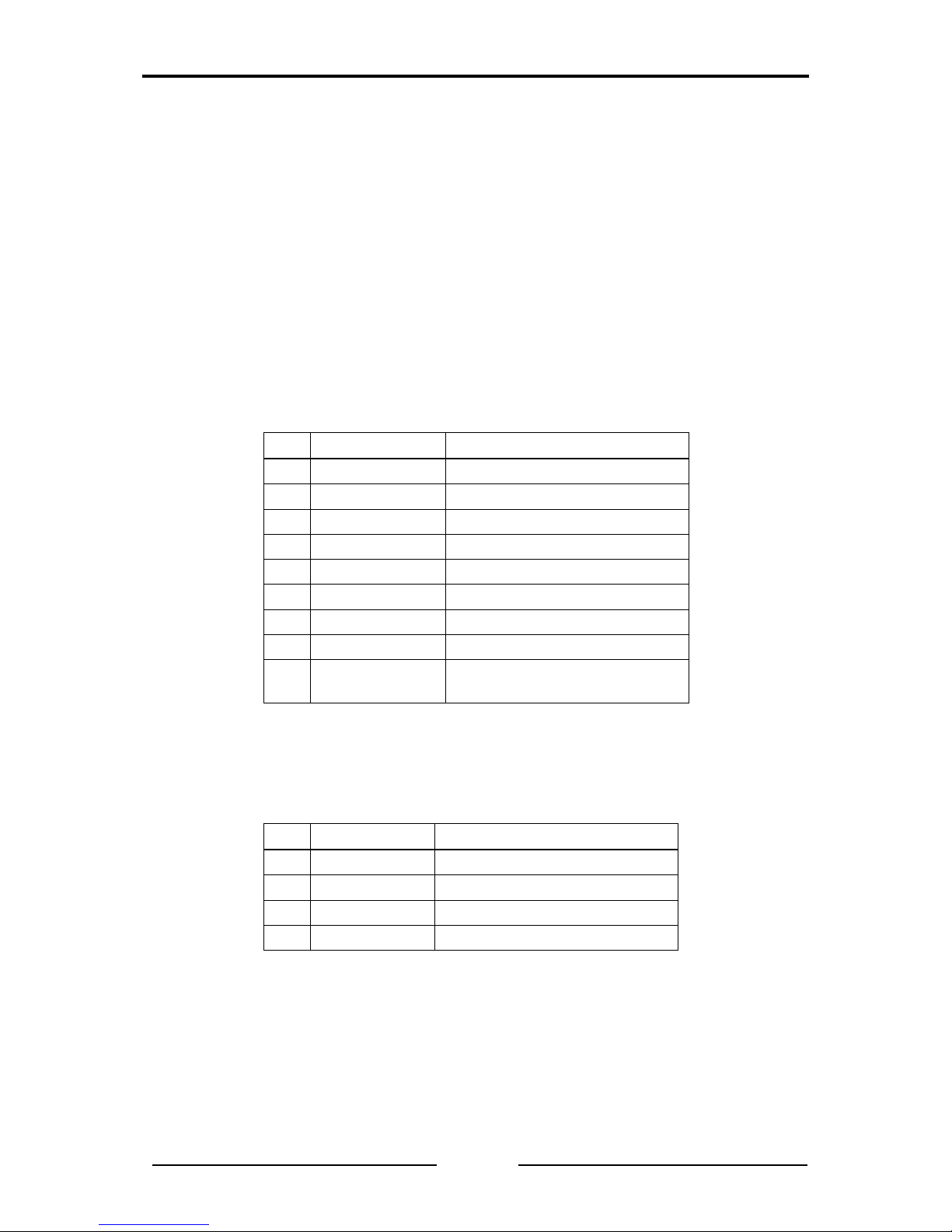
2.1 Pin Assignment ....................................................................... 8
2.1.1 CAN Connector ........................................................................ 8
2.1.2 USB Connector ........................................................................ 8
2.2 Battery Compartment ............................................................. 9
2.3 Trigger Output ......................................................................... 9
3 Operation ...................................................................................... 10
3.1 Switching On and Off ........................................................... 10
3.2 Display ................................................................................... 10
3.3 Keyboard ............................................................................... 10
4 Summarized Tests ....................................................................... 12
4.1 Line Parameters .................................................................... 12
4.2 Operating Parameters .......................................................... 18
4.2.1 Operating Mode Layer 2 ........................................................ 18
4.2.2 Operating Mode CANopen ..................................................... 23
5 Individual Tests ............................................................................ 24
5.1 Wiring Test ............................................................................ 25
5.2 Termination Resistors .......................................................... 28
5.3 Line Length ........................................................................... 30
5.4 Line Impedance ..................................................................... 32
5.5 Power Supply ........................................................................ 34
5.6 Baudrate Detection ............................................................... 35
5.7 Layer 2 – Identifier Scan ....................................................... 37
5.8 CANopen – Node ID Scan .................................................... 39
5.9 Bus Load ............................................................................... 41
5.10 Layer 2 – Signal Levels per Identifier .................................. 44
5.11 CANopen – Signal Levels per Node ID ................................ 47
5.12 Trigger Output ....................................................................... 50

Content
4
CANcheck Manual, Version 2.1
6 Error Messages and Indica tions ................................................. 52
6.1 Error Message after Switching On....................................... 52
6.2 Error Messages when CAN Nodes Are Not Switched Off .. 52
6.3 Error Message with Low-Impedance Resistance ............... 53
6.4 Error Message with Inverted Polarity .................................. 54
6.5 Error Message after Cancelling a Test ................................ 55
6.6 Error Message with Missing Results ................................... 55
6.7 Indication of a Non-Periodic Identifier ................................ 56
6.8 Indication of an Identifi er wit hout Us a ble Bits ................... 57
7 Results .......................................................................................... 59
7.1 Show and Delete ................................................................... 59
7.2 Store to File, Load from File, Del e t e Fil e ............................. 63
7.3 Plausibility Check ................................................................. 67
8 Remote Control ............................................................................ 68
9 Settings......................................................................................... 72
10 USB Driver .................................................................................... 73
10.1 Installation of the USB Driver .............................................. 73
10.2 Initial Connection of CANcheck and PC.............................. 75
11 Appendix ...................................................................................... 79
11.1 Technical Specifications ...................................................... 79
11.2 Criteria for Plausibility Check .............................................. 80
11.2.1 Line Length and Termination Resistors ................................ 80
11.2.2 Line Length and Baudrate .................................................... 80
11.2.3 Line Length and Signal Levels ............................................. 80
11.3 Accessories .......................................................................... 81
11.4 Information on the Use of CANcheck .................................. 82
11.5 Information on Disposal of Waste Equipment .................... 82
11.6 Information on EMC .............................................................. 83
11.7 Declaration of Conformit y .................................................... 84

Introduction
5
CANcheck Manual, Version 2.1
1 Introduction
1.1 Overview
The CANcheck allows simple testing of CAN networks during commissioning,
maintenance and troubleshooting. The battery-operated, portable device is
connected to the CAN network to be tested and operated via a clearly structured
menu.
The CANcheck measures line paramete rs – with network switched off
1
– and
operating parameters – with network switched on.
Via line parameters it is checked whether the CAN network was correctly
installed. Short-circuits, interruptions and incorrect cable prop erties are quickl y
detected.
Via operating parameters it is checked whether the nodes in th e CAN network
are working correctly. Missing identifiers and poor signal levels are quickly
detected and can be allocated to the individual CAN nodes.
1
Generally in the case of tests of line parameters, all CAN nodes should be disconnected from the CAN
network. Switched off nodes with a high internal resistance can remain connected.

Introduction
6
CANcheck Manual, Version 2.1
1.2 Functions and Performa nce Fe atures
Notice
HMS recommends to calibrate the CANcheck every two years to ensure the
accuracy of measurement. For further information please contact HMS.
Tests of the Line Parameters with Network Switched Off
• Resistance measurement between all pins of the CAN connector
(assignment in accordance with CiA) and analysis based on pre-defined limit
values
• Measurement of the termination resistors
• Determination of the cable length
• Determination of the cable impedance
Tests of the Operating Parameters with Network Switched On
• Measurement of the voltage between CAN_V+ and CAN_GND
• Determination of the baudrate of the tested CAN network (list in accordance
with CiA) and test of polarity
• Measurement of the bus load of the tested CAN network and of the
proportion of error telegrams
• Operating mode layer 2: determin ation of all transmitted 11-bit and 29-bit
identifiers and display of the frequency of reception
• Operating mode layer 2: absolute and differential signal level listed by
identifier
• Operating mode CANopen: frequency of reception and signal level listed by
node ID
Other Performance Features
• Summarized tests with test instructions, test result, continued after
confirmation
• All test results are stored and can be seen on the display after the test
• Plausibility check of stored test results
• Permanent storage of up to 4 test results
• The test results can be transferred to the PC for printing and filing
• Test instructions and results in German or English
• Power save mode
• Power-on self-test of the device

Introduction
7
CANcheck Manual, Version 2.1
1.3 Support
Read this manual before using the CANcheck.
For more information on our products, FAQ lists and installation tips, refer to the
support section of our website (www.ixxat.com), which also contains information
on current product versions and available updates.
If you have any further questions after studying th e information on our website
and the manuals, please co ntact our support dep artment. The s upport section
on our website contains the relevant forms for your su pport re quest. In o rder to
facilitate our support work and enable a f ast response, please pro vide precise
information on the individual p oints and describe your question or problem in
detail.
If you would prefer t o contact our support department by phone, please also
send a support request via our website first, so that our support department has
the relevant information available.
1.4 Returning Hardware
In order to be able to process returns q uic kly and corre ctl y, ple ase ap pl y for an
RMA number before each return. Use our on-line “RMA form” for your
application, which you can find on our website in the Support section.
After applying for the RMA number, you will receive a return deliver y note from
us, which you should enclose with your return delivery. In the case of returns
without an RMA number or retur n delivery note, we reserve t he right to return
them at your expense.
A detailed description of the RMA procedure can be found on our website in the
Support section.
Ports
8
CANcheck Manual, Version 2.1
2 Ports
The CANcheck has one CAN connector, one USB connector and a battery
compartment. The trigger output is connected to 2 reserved pins of the CAN
connector.
2.1 Pin Assignment
2.1.1 CAN Connector
The pin assignment on the CAN connector corresponds to CiA DS-102. The
trigger output is connected to 2 pins, which are marked as “reserved” in CiA DS-
102. The trigger output is gal vanicall y isolated fro m the CAN check ground and
has an internal resistance of 1 kΩ.
Pin
Signal
Description
1
- Reserved
2
CAN_L
CAN bus signal (dominant low)
3
CAN_GND CAN ground
4
TRIGGER_SHLD Return wire of the trigger output
5
CAN_SHLD Optional shield
6
GND Optional CAN ground
7
CAN_H CAN bus signal (dominant high)
8
TRIGGER Trigger output
9
CAN_V+
Optional external power supply
Vcc
2.1.2 USB Connector
If the CANcheck and the PC are connected via USB, the device is supplied from
the PC. The USB connector is galvanically isolated from the CANcheck ground.
Pin
Signal
Description
1
+5V Power supply
2
D- Negative data line
3
D+ Positive data line
4
GND Ground

Ports
9
CANcheck Manual, Version 2.1
2.2 Battery Compartme nt
The CANcheck is powered by 4 x 1.5 V batteries or 4 x 1.2 V rechargeable
batteries Mignon (AA). The batter y compartment is on the back of the device.
To replace the batteries a slotted screwdriver (blade width approx. 5 mm) is
required. Use it to press the plastic spring of the catch together and carefully lift
off the cover.
Note:
• The rechargeable batteries canno t be recharged via the USB connector.
Remove the rechargeable batteries from the battery compartment and
recharge them in a commercial battery charger.
• For rechargeable batteries, the capacity given by “Settings/Battery voltage”
is not valid. It is only valid for batteries.
• For rechargeable batteries, check the voltage given by “Settings/Battery
voltage”. Recharge the rechargeable batteries when the voltage drops
below 4.8 V.
2.3 Trigger Output
When a configurable 11-bit or 29-bit-i dent ifier or an er ror fra me is recei ved, the
CANcheck generates a signal pulse on the trigger o utput. T he signal pu lse ha s
the following properties:
• positive and negative signal pulse at the end of the telegram
• 10 V peak-peak without load
To use the trigger output, connect the CAN/trigg er cable (see section 11.2
) to
the CANcheck. The SUB-D9 connector with CAN cable and BNC cable belongs
to the CANcheck. The SUB-D9 connector with CAN cable belo ngs to the CAN
network.
Usually, an oscillosco pe is triggered b y the trigger outp ut. The telegram of the
configured 11-bit or 29-bit identifie r or the error frame is then displa yed on the
oscilloscope. In this way the level measurements of the CANcheck can be
supplemented with measurements with the oscill osco pe.

Operation
10
CANcheck Manual, Version 2.1
3 Operation
The CANcheck has a display and a ke yboard. It is switched on and off via the
keyboard.
3.1 Switching On and Off
Switch on the CANcheck by pressing any key for more than 1 second. The
message “Self-test passed” appears for 1 second on the display. Then the
information on the use of CANcheck is displayed (see chapter 11.4). Confirm
this information with the OK key. Then the system menu is displayed.
In power save mode (default setting), the CANcheck automaticall y switches off
after 10 minutes without a user input. Generally the CANchec k consumes little
power while waiting for a user input.
To switch the CANcheck off immediately select the menu item Settings and the
sub-item Switch off. Confirm the selection with Off.
3.2 Display
The CANcheck is equipped with a g raphical display with 128 x 64 pixels. The
display shows the menu items and the test results.
One header line and up to 6 lines of text are sho wn on th e disp lay. I f the space
is not sufficient, the content can be moved with the help of the keyboard.
The display has a background illumination. In the default setting the background
illumination is switched off. To switch the background illumination on, select the
menu item Settings and the sub-item background illumination. Select
Automatic and confirm the selection.
In the Automatic setting, the backlight switches on every time a key is pressed
and off again automatically after 20 seconds.
The background illumination is always switched on when the CANcheck is
connected to a PC via a USB cable.
3.3 Keyboard
The CANcheck is operated via a keyboard with 6 membrane switches. Move the
selection bar from menu item to menu item with the keys UP and DOWN.
Confirm your selection with the OK key. The selected menu item then becomes
the new header.
The CANcheck is operated via t he system menu and sub-menus. Move from
the system menu to the sub-menu with the OK key. Move back with the ESC
key.
Every menu item and test can be cancelled with the ESC key.
If the pixels of the display are not sufficient, move the contents to the left or right
with the keys LEFT and RIGHT. With long lists scroll t hrough the text with the

Operation
11
CANcheck Manual, Version 2.1
keys UP and DOWN. The symbols ◄ ▲ ▼ ► in the header bar indic ate whether
moving and scrolling is supported.
In some sub-menus, virtual ke ys appear on the d isplay. With the ke ys UP and
DOWN change between the virtual keys shown above or below each other. With
the keys LEFT and RIGHT change between virtual keys shown ne xt to each
other. The selected virtual key appears in black with white lette ring.
In some sub-menus, numeric al values ca n b e enter ed. Cha nge the values with
the keys UP and DOWN and the decimal place with the keys LEFT and RIGHT.
The selected place appears in black with a white numerical val ue.

Summarized Tests
12
CANcheck Manual, Version 2.1
4 Summarized Tests
The summarized tests are intended for the rout ine execution and repetiti on of
the tests of CAN networks. The user receives test instructions before the test.
When the CANcheck has checked the test result , the user rec eives one of the
messages:
• TEST PASSED
• TEST FAILED
With some tests the CANcheck cannot check the te st result because th ere are
no generally valid nominal values for it. This applies to the cable length, the
power supply, the baudrate and the bus load. After these tests the user receives
the message:
• TEST EXECUTED
As soon as the user has acknowledged one of these messages, the test is
continued.
Tests with the CAN network switched off are executed with the menu item Line
parameters. With these tests it is checked whether the CAN network was
correctly installed.
Tests with the CAN network switched on are executed with the menu item
Operating parameters. With these tests it is checked whether the nodes in the
CAN network are working correctly.
4.1 Line Parameters
To test the line parameters, connect the CANcheck – if possible – where one of
the two termination resistors of the CAN net work is located. With the Y cable
connect the CANcheck between the CAN network and the termination resistor.
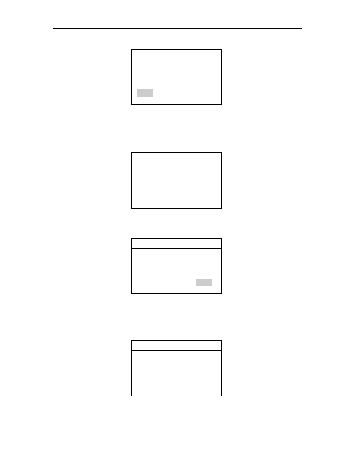
From the system menu, start the tests of the line parameters by selecting the
relevant menu item and OK. With the keys UP and DOWN, move the selection
bar from menu item to menu item. Confirm the selection with the OK key. The
selected menu item becomes the new header.
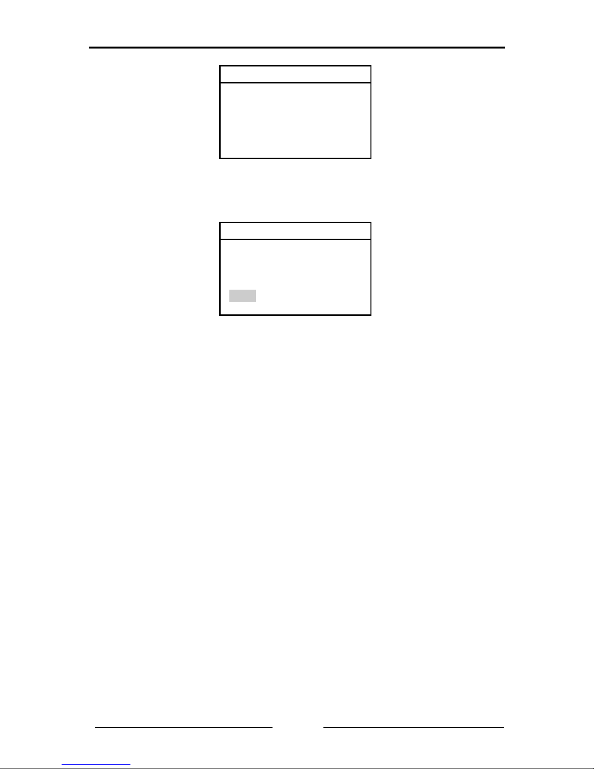
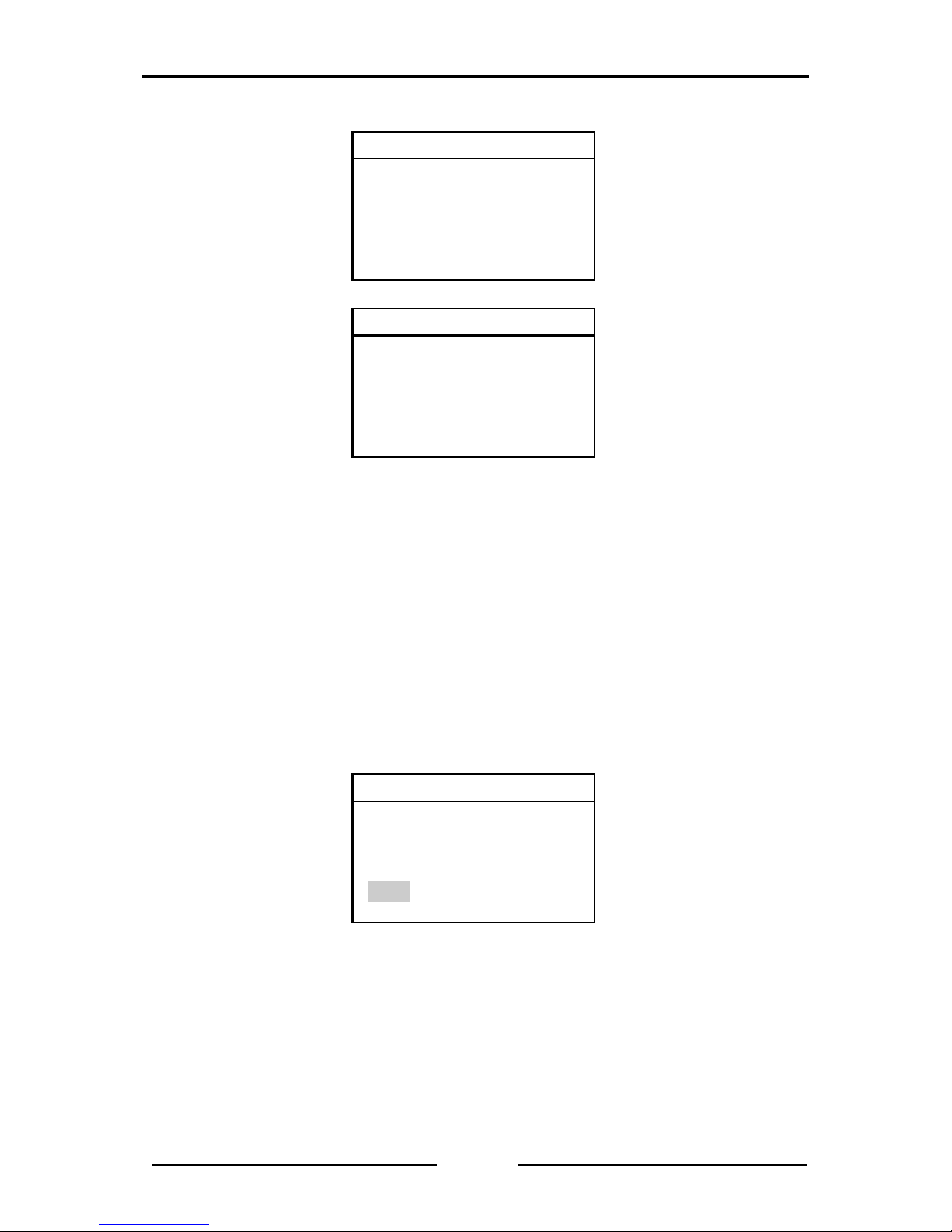
System menu
-Line parameters
-Operat. parameters
-Individual tests
-Stored results
-Remote control
-Maintenance
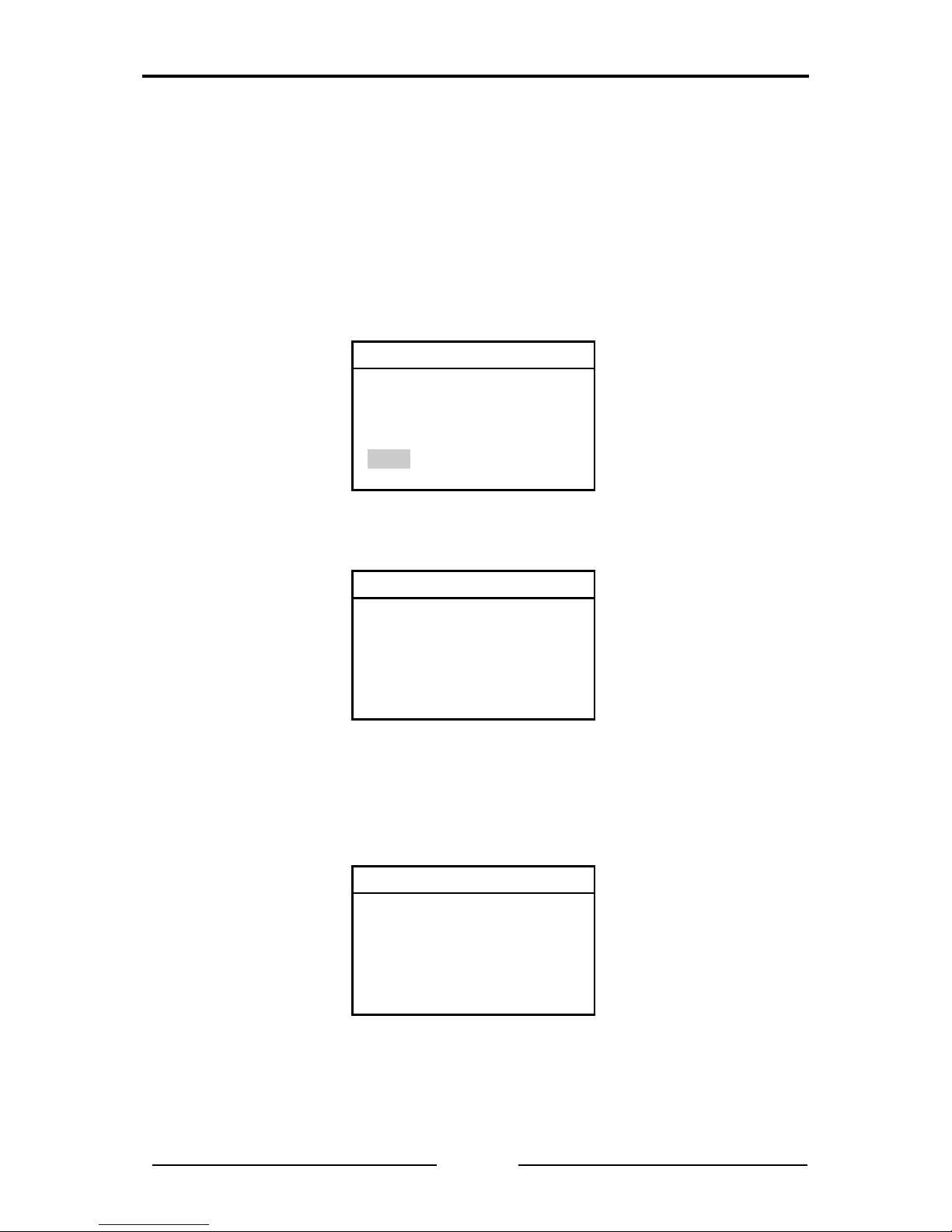
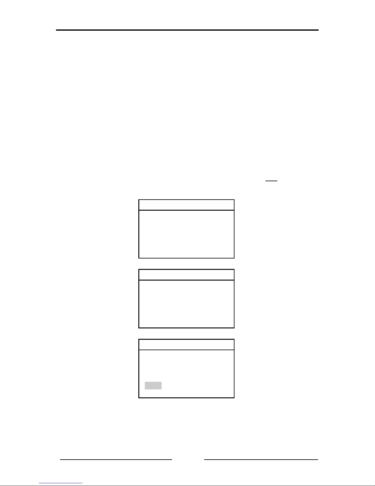
If the test is started when the CAN network is switched on, the following error
message is displayed, because tests of the line parameters are not possible
when the CAN network is switched on.

Summarized Tests
13
CANcheck Manual, Version 2.1
Line parameters
Voltage detected
on CAN bus
Test rejected
Return to the system menu with the ESC key. Start the next test with th e CAN
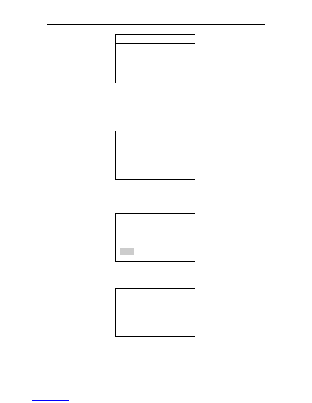
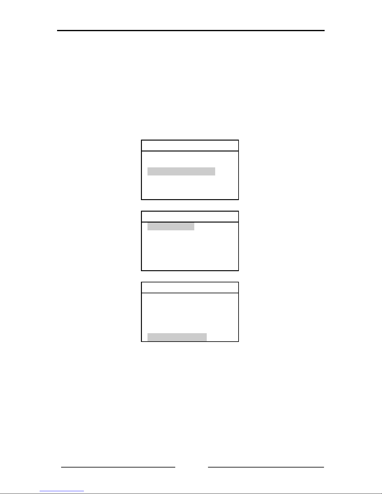
network switched off. The test instructions are displayed.
Wiring test
-Disconnect all nodes
-Terminate CAN bus
on both ends
OK Start test
The header shows that the wiring is test ed first. The test i nstructions ar e to be
understood as follows: generally for tests of the line parameters, all CAN nodes
should be disconnected from the CAN network. Switched off CAN nodes that
have a high resistance between CAN_H, CAN_L and ground may remain
connected. As the resistors of all conne cted CAN nod es are parallel, ho wever,
the resistance of every individual CAN node must then be greater than the
“number of CAN nodes” x 1 kΩ.
If this condition is met, press the OK key.
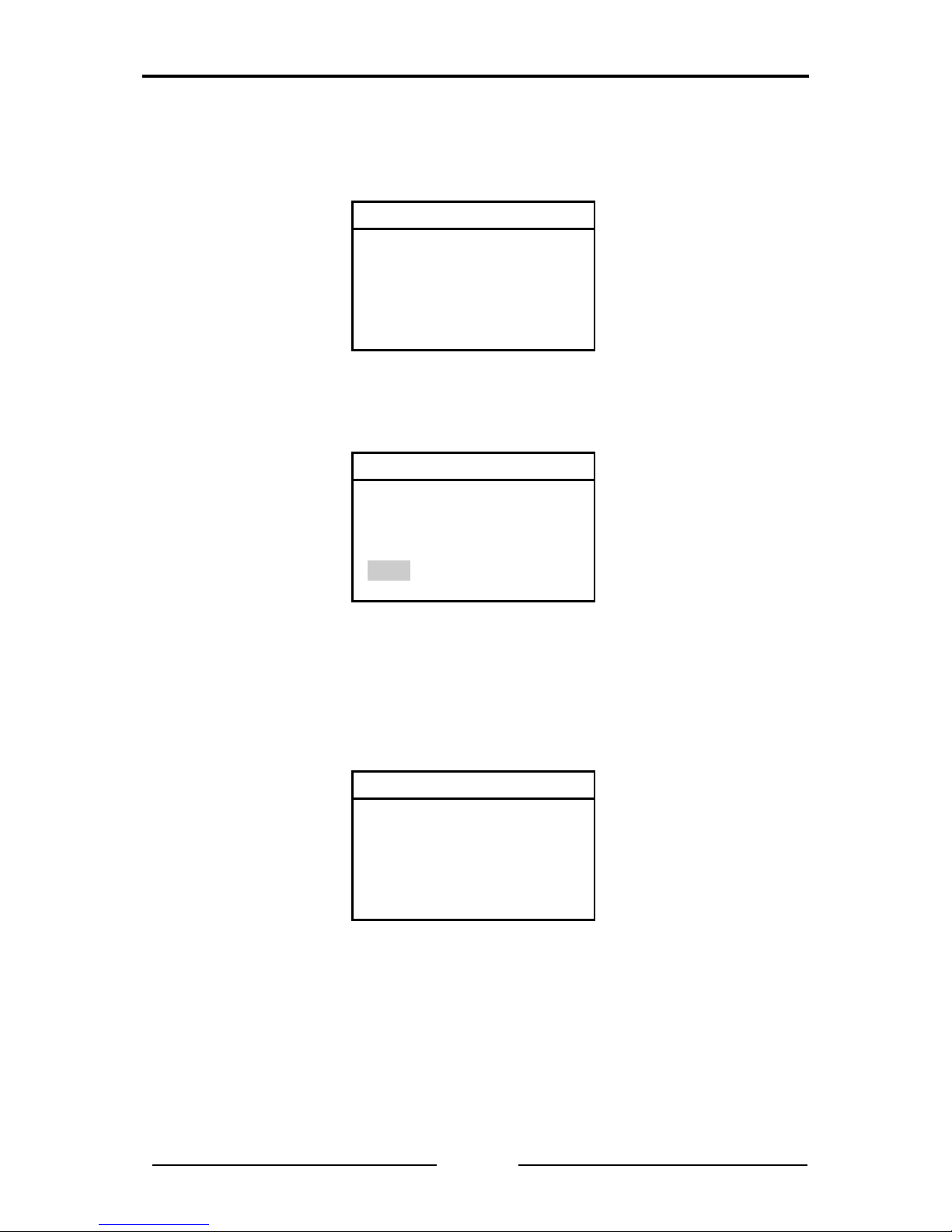
During the measurement a message appears.
Wiring test
Status: scanning
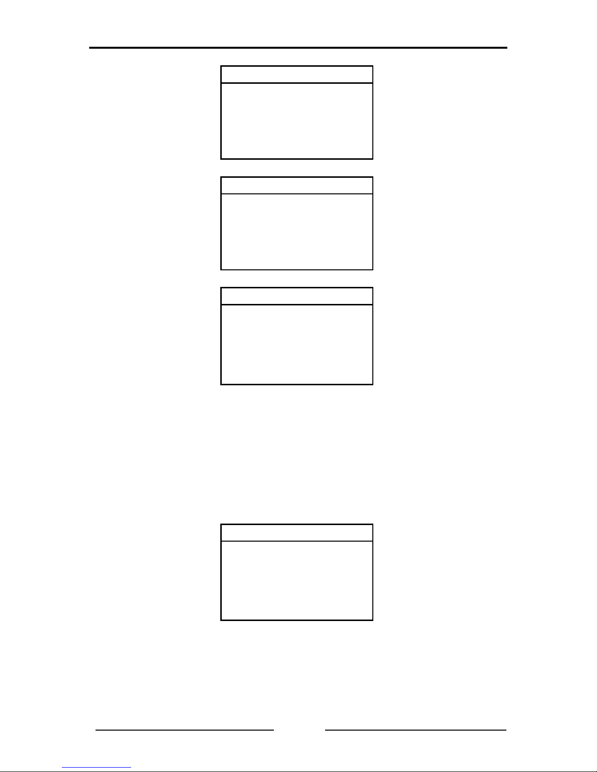
In the case of correct wiring, the message TEST PASSED and two virtual keys
appear on the display at the end of the test.

Summarized Tests
14
CANcheck Manual, Version 2.1
Wiring test
TEST PASSED
NEXT INFO
Start the next test with the virtual key NEXT. To look at the test results with the
virtual key INFO, change to the virtual key INFO with the key RIGHT. This
appears in black with white lettering. Confirm the selection with OK.
Here is the first part of a positive test result. The symbol ▼ in the header means
that more lines follow. Scroll down with the key DOWN.
Wiring test ▼
CAN_H ->
CAN_L : 65Ω[OK]
CAN_GND : 1.56kΩ[OK]
CAN_SHLD: >1MΩ[OK]
GND : >1MΩ[OK]
Continue the tests of the line par amete rs by re turni ng to th e hi gher ord er menu
with the ESC key. There start the n ext test with the virtual key NEXT and the
OK key.
Before the measurement of the line impedance, the next test instruc tions are
displayed:
Line impedance
-Disconnect all nodes
-Remove termination R
on near end
OK Start test
The test instructions are to be und erstood as follows: the termination resistor
must be removed fro m the line end t o which the CA Ncheck is connect ed. The
other line end must be terminated.
The line impedance can only be corr ectly measur ed if you ha ve connected th e
CANcheck where normally one of the two termination resistors of the CAN
network is located.
In the case of correct line impedance, the message TEST PASSED and the
virtual keys NEXT and INFO appear in the display at the end of the test.
Summarized Tests
15
CANcheck Manual, Version 2.1
Line impedance
TEST PASSED
NEXT INFO
The stored test results can be seen at the end of the test.
Start the next test with the virtual key NEXT and the OK key. Before the
measurement of the line length, the next test instructions are displayed:
Line length
-Disconnect all nodes
-Remove termination R
on both ends
OK Start test
If test instructions were not followed, the test result is negative.
Line length
TEST FAILED
NEXT INFO
With the virtual key INFO an erro r message is displayed. A more detailed error
message is only given with the measurement of the line length as an individu al
test.
Line length
Test rejected
Summarized Tests
16
CANcheck Manual, Version 2.1
To receive an error-free test result, it is necessary to repeat the tests of the line
parameters. Return to the system menu by press ing the ESC key twice. St art
the tests of the line parameters by pressing the OK key.
Confirm the test instructions and the result of the wiring test as well as the test
instructions and the result of the meas urement of the termination resistors by
pressing the OK key four times.
Remove the termination resistors at both ends of the CAN network. If s witched
off CAN nodes are still connected to the CAN networ k, the test is onl y possible
if they have a high resistance between CAN_H, CAN_L and ground.
The line length can only be correctly measured if the CANcheck is connected to
the line end, where normally one of the two termination resis tors of the CAN
network is located.
If the measurement is completed successfully, the message TEST EXECUTED
is displayed. The CANcheck has consequently not checked the test result.
Line length
TEST EXECUTED
NEXT INFO
The test result is displayed with the virtual key INFO.
Line length
96 m
Continue the tests of the line par amete rs by re turni ng to th e hi gher ord er menu
with the ESC key. Start the next test with the virtual key NEXT and the OK key.
Now the termination resistor is measured. The test instructions are the same as
for the wiring test.
Summarized Tests
17
CANcheck Manual, Version 2.1
Term. resistors
-Disconnect all nodes
-Terminate CAN bus
on both ends
OK Start test
In the case of correct termination resistor s, the message TEST PASSED and
two virtual keys appear in the display at the end of the test.
Term. resistors
TEST PASSED
END INFO
End the tests of the line parameters with the virtual key END. All test results can
be displayed in Stored results.

Summarized Tests
18
CANcheck Manual, Version 2.1
4.2 Operating Parameters
To test the operating parameters, there are two ways to connect the CANcheck
to the CAN network:
• If there is a free SUB-D9 socket in the CAN network, the CANcheck can be
connected to this socket via the 1-to-1 cable.
• If this is not the case, the CANc heck can be loo ped in between any CAN
node and the CAN network via the Y cable.
Operating parameters can be measured in two operating modes.
• In the operating mode “layer 2”, all 11-bit and 29-bit identifiers are
measured. The signal levels are listed by identifier.
• In the operating mode “CANopen”, only those identifiers are measured
from which the node ID clearly originates. T he signal levels are listed by
node ID.
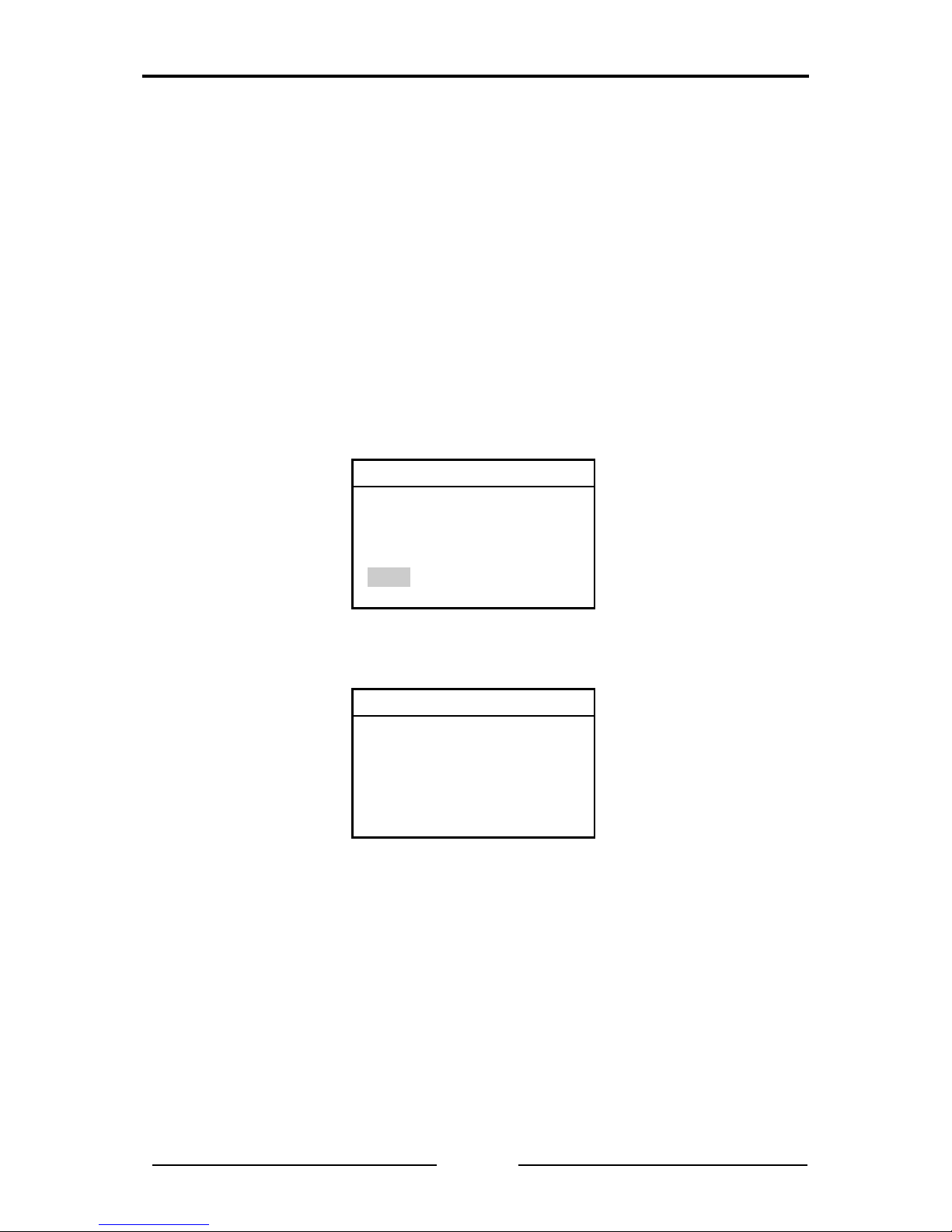
4.2.1 Operating Mode Layer 2
Start the operational tests from the system menu by selecting the relevant menu
item and OK. Move the selection bar from menu item to menu item with the keys
UP and DOWN. Confirm the selection with the OK key. The first test becomes
the new header.
First the power supply is measured. If the measurement is completed
successfully, the message TEST EXECUTED appears in the display at the end
of the test. The CANcheck has consequently not checked the test result.
System menu
-Line parameters
-Operat. parameters
-Individual tests
-Stored results
-Remote control
-Maintenance
Power supply
TEST EXECUTED
NEXT INFO
Start the next test with the virtual key NEXT. First, however, we want to look at
the test results with the virtual key INFO. For this, change to the virtual key INFO
with the key RIGHT. This appears in black with white lettering. Confirm the
selection with OK.
Summarized Tests
19
CANcheck Manual, Version 2.1
Power supply
CAN_V+ -> CAN_GND
0.0 V
Continue the operational tests b y returning to the higher order menu with the
ESC key. Start th e baudrate detection with the virtual key NEXT and the OK
key. If the display shows the following message, either all CAN nodes are
switched off or they are not sending any telegrams.
Baudrate detection
Status: scanning
Wait for CAN traffic
In this case, cancel the test with the ESC k ey. Due to the cancel lation, the test
result is negative.
Baudrate detection
TEST FAILED
NEXT INFO
Via the virtual key INFO an error message is displayed.
Baudrate detection
Test rejected
Summarized Tests
20
CANcheck Manual, Version 2.1
To receive an error-free test result, it is necessary to repeat the operational
tests. Return to the system menu by pressing the ESC key twice. Start the
operational tests by pressing the OK key.
Acknowledge the result of the measurement of the power suppl y by pressing
the OK key. Switch the CAN nodes on and ensure that the CAN nodes are
sending telegrams.
When the baudrate detection is successfully completed, the message TEST
EXECUTED is displayed. The CANcheck has consequently not checked the test
result.
Baudrate detection
TEST EXECUTED
NEXT INFO
Via INFO the test results are displayed.
Baudrate detection
500 kBit/s
If CAN_H and CAN_L are inverted in all nodes in the CAN network – even in
this case communication is possibl e - the CANcheck detects the baudrate but
classifies the polarity as erroneous. In this case the following error message
appears:
Baudrate detection
H-L inverted [ERROR]
500 kBit/s
Continue the operational tests b y returning to the higher order menu with the
ESC key. Start the next test with the virtual key NEXT and the OK key.
Summarized Tests
21
CANcheck Manual, Version 2.1
Now the bus load and the error telegrams are measured. Duri ng the scan time
(default setting 10 s) the current measured values ar e displ a yed e ver y secon d.
In this way changes can be observed.
Busload
Scan time : 10 s
Bus load : 1 %
Error frames : 0 %
If the measurement is completed successfully, the message TEST EXECUTED
is displayed. The CANcheck has consequently not checked the test result.
Bus load
TEST EXECUTED
NEXT INFO
The test result are displayed via INFO. Here is the begi nning of the table wit h
minimum value, maximum value and average value. The symbols ▼
► in the
header show that there are more lines in the table. Scroll down the tabl e with
the key DOWN. To see the end of a long line, move the table in the display with
the key RIGHT.
Busload ▼
►
Scan time : 20 s
MIN MAX AVG
Bus load
Continue the operational tests b y returning to the higher order menu with the
ESC key. Start the next test with the virtual key NEXT and the OK key.
In this test the CANcheck records all identifiers that are received during the scan
time (default setting 10 s). Then the CANcheck measures the different ial and
absolute signal level for each identifier.
During the recording of the identifiers, the display shows the relevant header.
The header changes as soon as the signal levels are measured.
Summarized Tests
22
CANcheck Manual, Version 2.1
Identifier scan
Status: scanning
Signal levels per id
Status: measuring
“Identifier scan” always lasts for the set scan time.
“Signal levels per identifier” lasts for the set maximum meas uring time at the
longest (default setting 60 s).
When the differential and the abs olute signal le vels of all identifier s have been
measured as often as is required for the averaging (default setting 3 times), the
measurement is already ended before the set measuring time has elapsed.
Note: it may take several minutes until the measurement is completed if
identifiers are transmitted at short intervals one after another (approx. 11 µs) or
the number of identifiers is large (maximum 2048).
In the case of correct signa l le vels, TEST PASSED is displ a yed. T he tol eranc e
ranges for the differential and absolute signal level are given in section 11.1.
Signal levels per id
TEST PASSED
END INFO
End the operational tests with the virtual key END. You can now see all test
results in Stored results.
Summarized Tests
23
CANcheck Manual, Version 2.1
4.2.2 Operating Mode CANopen
Section 4.2.1 shows the operational test s in the operatin g mode “la yer 2”. This
is the default setting.
Switch to operating mode “CANopen” by selecting the menu item Settings in
the system menu and pressing the OK key. Then select the menu item
Operating mode and press the OK key. Wit h the key DOWN select “CANopen”
and confirm with OK. Return to the system menu with the ESC key.
If the operational tests are repeated, only the results of th e last test differ from
section 4.2.1.
The CANcheck records the node IDs and not the message identifiers in the
operating mode “CANopen”. According to CANopen standard, the n ode ID is
uniquely contained:
• in the identifier, which the node sends with “Node guarding protocol” or with
“Heartbeat protocol”
• in the identifier which the node transmits on access via the first server SDO
and which is formed according to the “pre-defined connection set”
Node ID scan
Status: scanning
Signal levels per no
Status: measuring
Signal levels per no
TEST PASSED
END INFO
The operating mode “CANopen” has no effect on the tests of the line
parameters.
Individual Tests
24
CANcheck Manual, Version 2.1
5 Individual Tests
The summarized tests from section 4 can also be executed i ndividuall y. In this
way, “problematic” tests can be quickly repeated. If the test cannot be executed,
a more detailed error message is displayed.
In the system menu, select the menu item Individual tests with the key DOWN
and press the OK key. The symbol ▼ in the following head er shows that the list
of individual tests does not fit in the dis play. Scroll through the list with the k ey
DOWN.
System menu
-Line parameters
-Operat. parameters
-Individual tests
-Results
-Remote control
-Maintenance
Individual tests ▼
-Wiring test
-Term. resistors
-Line length
-Line impedance
-Power supply
-Baudrate detection
Individual tests ▲ ►
-Power supply
-Baudrate detection
-Identifier scan
-Bus load
-Signal levels per id
-Trigger output
Now select an individual test with the keys UP and DOWN and confirm with OK.

Individual Tests
25
CANcheck Manual, Version 2.1
5.1 Wiring Test
In the wiring test the CANcheck m easur es the resist ance bet ween a ll lin e p airs
on the CAN connect or. T he pi n as sign me nt of t he CA N c onne c tor c orresponds
to CiA DS-102 (see section 2.1.1).
The CANcheck checks whether the resistance between CAN_H and CAN_L
corresponds to the termination resistors. The tolerance range for the termination
resistors is given in section 11.1.
For all other line pairs, the nominal value is “high resistance”. The tolerance
range for “high resistance” is given in 11.1.
The following resistances are exceptions:
CAN_SHLD → CAN_GND
CAN_SHLD → GND
GND → CAN_GND
According to CiA, the lines CAN_SHLD and GN D ar e optional. Therefore there
are no nominal values for these resistances.
For the wiring test the CANcheck can be connected to the CA N net work at an y
point. Switch the CAN network off before the wiring test and disconnect all CAN
nodes from the network. Switched off CAN nodes with a high resistance
between CAN_H, CAN_L and ground can remain connected. As the resistors of
all connected CAN nodes ar e parallel, the resistance of ev ery individual CAN
node must then be greater than the “number of CAN nodes” x 1 kΩ.
Select the menu item Wiring test with the keys UP and DOWN and press t he
OK key.
Individual tests ▼
-Wiring test
-Term. resistors
-Line length
-Line impedance
-Power supply
-Baudrate detection
When the CAN network is switched off, the test instructions appear. Error
messages are explained in section 6. W hen the test instructions are executed,
start the test with the OK key.
During the measurement, a message appears. After the measurement, the test
result appears.
Individual Tests
26
CANcheck Manual, Version 2.1
Wiring test
-Disconnect all nodes
-Terminate CAN bus
on both ends
OK Start test
Wiring test
Status: scanning
Wiring test ▼
CAN_H ->
CAN_L : 65Ω[OK]
CAN_GND : 1.56kΩ[OK]
CAN_SHLD: >1MΩ[OK]
GND : >1MΩ[OK]
During the measurement, one line i s take as a reference (measuring point 1)
and the resistance is measured against all other lines (measuring point 2).
The test result shows the measuring point 1 in the header. The list of the
measuring points 2 follows with the resistance values. This is followed by a blank
line.
The symbol ▼ in the header means that not all test results fit on the display.
Scroll through the test results with the key DOWN.
Wiring test ▲ ▼
CAN_L ->
CAN_GND : 1.54kΩ[OK]
CAN_SHLD: >1MΩ[OK]
GND : >1MΩ[OK]
CAN_V+ ->
 Loading...