

Page 1

TrueNAS
®
ES12 Expansion Shelf
Basic Setup Guide
Version 1.2
Page 2
Copyright © 2019 iXsystems, Inc. All rights reserved.
All trademarks are the property of their respective owners.
1ES12ExpansionShelf
The TrueNAS®ES12 is a 2U, 12-bay, SAS3 (12 Gb/s) expansion shelf with dual expansion controllers and redundant
power supplies.
Note: TrueNAS®units are carefully packed and shipped with trusted carriers to arrive in perfect condition. If there
is any shipping damage or any parts are missing, please take photos and contact iXsystems support immediately at
support@iXsystems.comor 1-855-GREP4-iX (1-855-473-7449) or 1-408-943-4100.
Please locate and record the hardware serial numbers on the back or side of each chassis for easy reference.
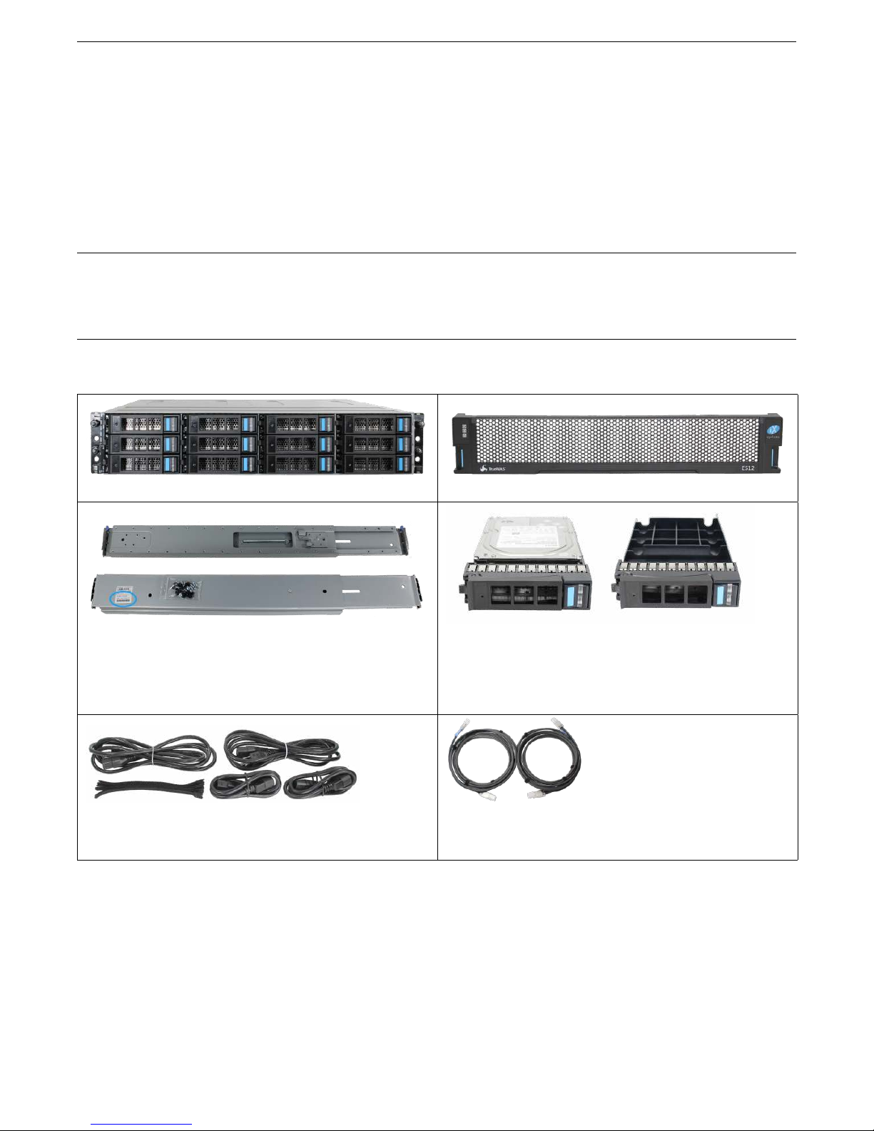
Carefully unpack the shipping boxes and locate these components:
ES12 Expansion Shelf ES12 Bezel
Set of rackmount rails. The rails have a specific front
end, identified by a label visible on the left above. The
front ends of the rails must be installed facing the
front of the rack.
Accessory kit with 2 IEC C13 to NEMA 5-15P power
cords, 2 IEC C14 to C14 cords, and a set of velcro cable ties
A total of 12 populated or empty “air baffle” drive
trays. Trays must be installed in all bays to maintain
proper airflow for cooling. Up to ten drive trays are
packed in a cardboard tray. Additional drive trays are
packed with the accessory kit.
Two 3-meter Mini SAS HD to Mini SAS HD cables
1
Page 3
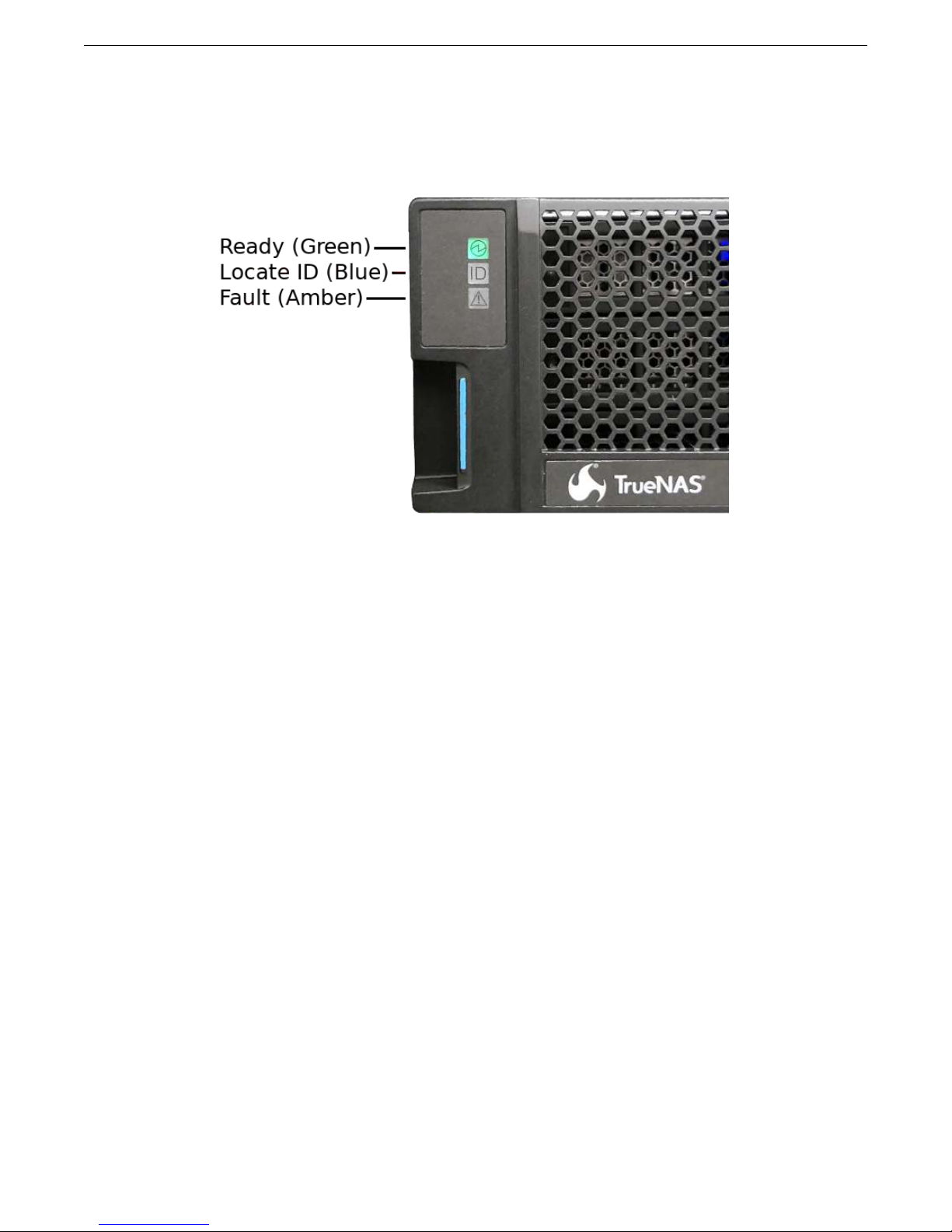
1.1 BecomeFamiliarWiththeES12System
The ES12 has front panel indicators for power, locate ID, and fault. The fault indicator is on during the initial poweron self-test (POST) and turns off during normal operation. It turns on if the TrueNAS®software issues an
(https://www.ixsystems.com/documentation/truenas/tn_options.html#alert).
alert
2
Page 4
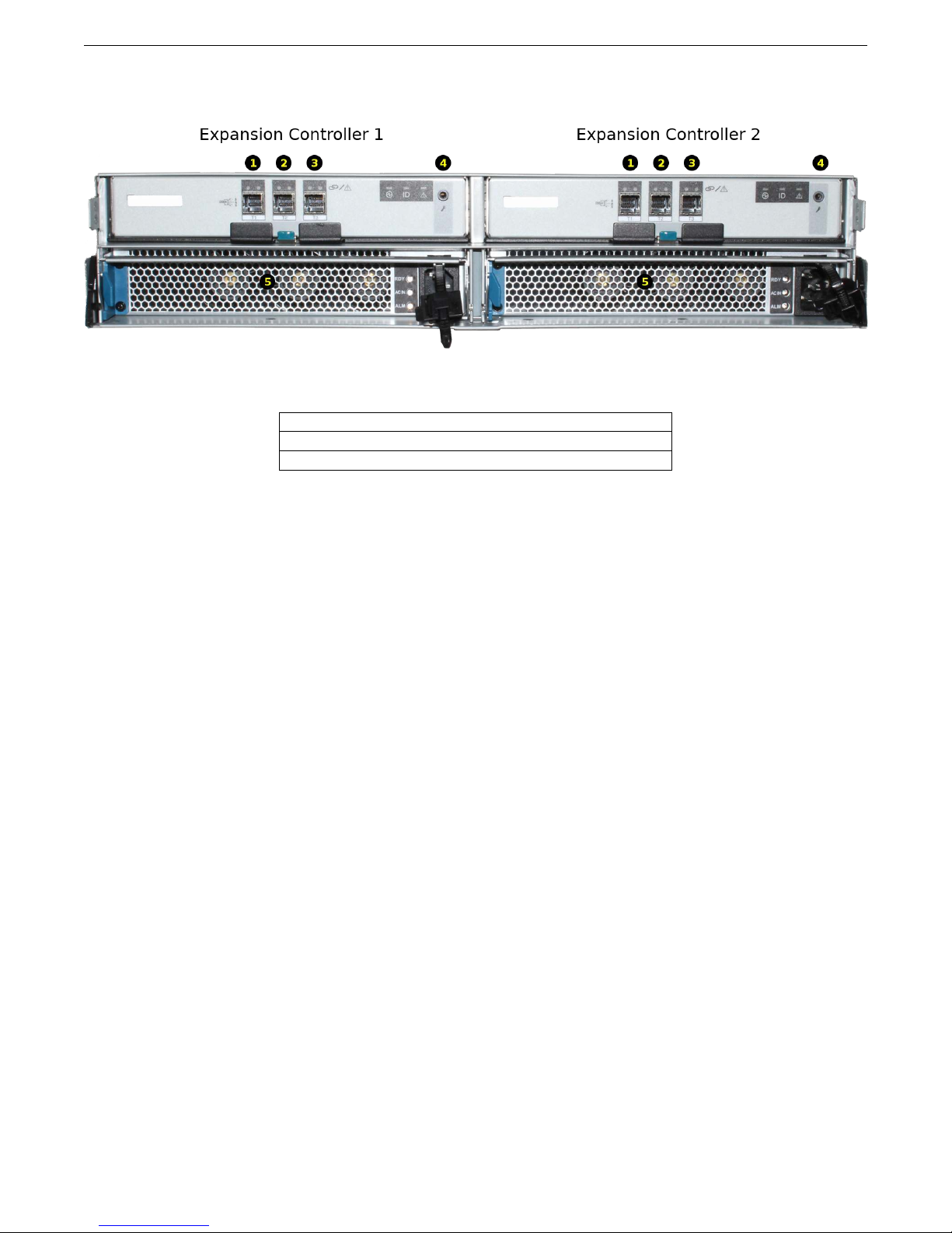
The ES12 has two expansion controllers in a side-by-side configuration:
1-3: HD Mini SAS3 connectors (T1-T3)
4: Debug port (TrueNAS®internal use only)
5: Redundant power supplies
3
Page 5

1.2 RailKitAssembly
On racks that are 30 inches deep or less, proceed to rail spring installation below.
Racks from 31 to 36 inches deep require installation of the included rail extenders. For these deeper racks, install
cage nuts on the outside rear of the rack. The tabs on the cage nuts must be horizontal as shown. Using the
included bolts, install the rail extender inside the rear of the rack. Repeat the process for the second extender, which
is a mirror image of the first.
If not already present, install a spring on the silver posts in the side of each rail.
Open the clamp latches on the ends of each rail. Place the rail in the rack with the front end toward the front of the
rack, aligning the pins on both ends of the rail with the mounting holes in the rack. Swing the clamp latch closed to
hold the rail in place. Use two of the supplied screws to secure the back end of the rail in place. Repeat the process
for the second rail.
Caution: Two people are required to safely lift the chassis for rack installation or removal. Do not install
drives until after the chassis has been installed in the rack, and remove all drives before removing the chassis from
the rack.
Carefully place the chassis onto the rails mounted in the rack. Push the chassis in until the ears are flush with the
front of the rack. Use two of the supplied screws to secure each ear to the rack.
4
Page 6

1.3 InstallDriveTrays
Drive trays are used to mount drives in the chassis. Each drive tray has a status LED which is blue when active or
amber if a fault has occurred.
A tray must be placed in each drive bay to maintain proper airflow for cooling. If fewer than twelve drives are
connected, empty “air baffle” trays must be placed in the empty bays.
A standard drive tray installation order simplifies support and is strongly recommended:
• SSD drives for write cache (W), if present
• SSD drives for read cache (R), if present
• Hard drives or SSD drives for data storage
• Air baffle filler trays to fill any remaining empty bays
Install the first drive tray in the top left drive bay. Install the next drive tray to the right of the first. Install remaining
drive trays to the right across the row. After a row is filled with drives, move down to the next row and start again
with the left bay.
This example shows the proper order for a write cache (W) SSD, a read cache (R) SSD, eight hard drives, and two
empty air baffle trays.
To load an individual drive tray into a bay, press the blue button to open the latch. Carefully slide the tray into a drive
bay until the left side of the latch touches the metal front edge of the chassis, then gently swing the latch closed until
it clicks into place.
5
Page 7

1.4 ConnectPowerCords
Do not plug the power cords into a power outlet yet. Connect a power cord to the back of one power supply.
Place the cord in the plastic clamp and press the tab into the latch to lock it in place. Repeat the process for the
second power supply and cord.
6
Page 8

1.5 ConnectSASCables
Plug the ES12 power cords into power outlets. Wait two minutes for the drives to start.
The ES12 is compatible with several TrueNAS®systems. Typical SAS cable connections for one or two ES12 expansion
shelves to TrueNAS®High Availability (HA) systems are shown here. When a TrueNAS®unit with only a single storage
controller is used, only cables #1 and #3 are connected.
X-Series
7
Page 9

M40
8
Page 10

M50
9
Page 11
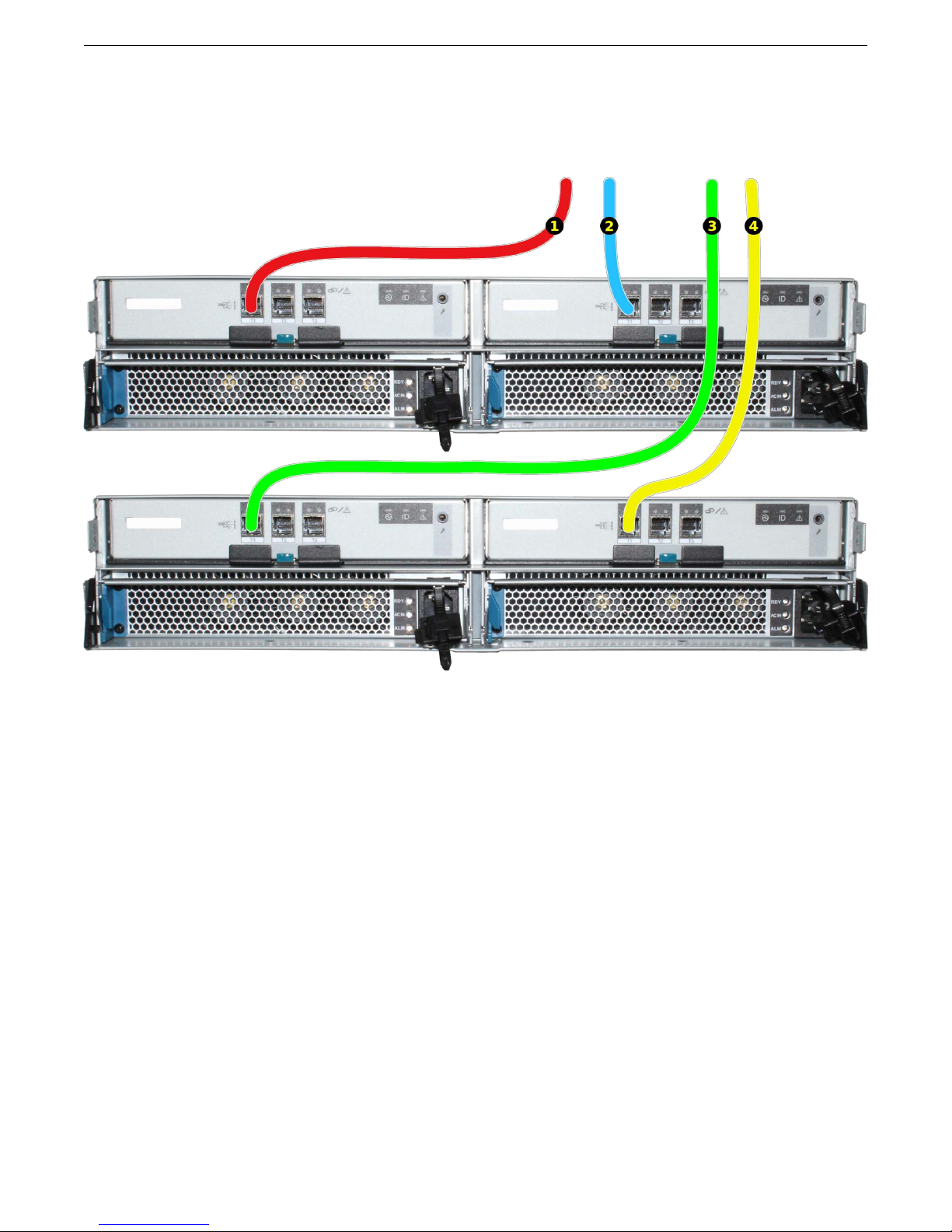
Connect SAS cables to the ES12 T slots. These are the typical SAS connections for one or two ES12 expansion shelves
connecting to a High Availability (HA) TrueNAS®system with two storage controllers. When a TrueNAS®unit with
only a single storage controller is used, only cables #1 and #3 are connected.
• Connect cable #1 to the ES12 expansion controller 1 T1 slot.
• Connect cable #2 to the ES12 expansion controller 2 T1 slot.
If a second ES12 is present:
• Connect cable #3 to the second ES12 expansion controller 1 T1 slot.
• Connect cable #4 to the second ES12 expansion controller 2 T1 slot.
10
Page 12

1.6 InstallBezel(Optional)
The included bezel is not required for operation. If desired, install the bezel by aligning it with the pins on the bezel
ears and pressing it into place.
1.7 UserGuide
The TrueNAS®User Guide with complete configuration instructions is available by clicking Guide in the TrueNAS
web interface or going directly to
https://www.ixsystems.com/documentation/truenas/.
2ContactingiXsystems
For assistance, please contact iX Support:
Contact Method Contact Options
Web https://support.ixsystems.com
Email support@iXsystems.com
Telephone Monday - Friday, 8:00AM to 5:00PM Pacific Standard Time:
• 1 (855) 473-7449 option 2 (US-only toll-free)
• 1 (408) 943-4100 option 2 (local and international)
Telephone After Hours (24x7 Gold Level Support only):
• 1 (855) 499-5131 (US-only toll-free)
• 1 (678) 835-6101 (local and international)
®
11
 Loading...