

IXOM CHLORGUARD User Manual
DOCUMENT No. CHL07-M
PART No. CHL01
REVISION 3.1.6
20/12/2015
CHLORGUARD USER'S MANUAL

Page 2
IMPORTANT INFORMATION
The equipment described in this manual is designed to be used in conjunction with liquefied chlorine
gas which is hazardous to personnel safety. It is important that persons employed in the vicinity of a
chlorine installation be given an appropriate level of training in chlorine safety practices and know the
location of safety equipment. Orica has wall charts and handbooks available which describe safe
practice in storing and handling chlorine.
This manual is provided for information purposes only.
All information included herein is subject to change without notice.
Orica should not be held responsible for any damages, direct or indirect, arising from or related to use
of this manual.

Page 3
TABLE OF CONTENTS Page
1 General ...................................................................................... 5
1.1 Typical Setup (70 kg cylinders) ..................................................................... 5
1.2 Typical Setup 920Kg Drums.......................................................................... 6
2 Key Components ...................................................................... 7
2.1 Control Panel ................................................................................................ 8
2.1.1 DC (UPS) power supply ........................................................................................ 11
2.1.2 PLC (Programmable Logic Controller) .................................................................. 11
2.1.3 GMS wireless module ........................................................................................... 11
2.1.4 Warning LED’s: Visual Alarm ................................................................................ 11
2.2 Support Bracket .......................................................................................... 12
2.3 Connecting Transmitting Key ...................................................................... 12
2.4 Actuator Types ............................................................................................ 13
2.5 Chlorine Transmitter & Sensor .................................................................... 13
3 OPERATION ............................................................................ 15
3.1 Overview ..................................................................................................... 15
3.1.1 Power Supply ........................................................................................................ 15
3.1.2 Battery Back-Up .................................................................................................... 15
3.1.3 PLC Programmable Logic Controller ..................................................................... 15
3.1.4 DC (UPS) power supply ........................................................................................ 15
3.1.5 Chlorine Sensor/Transmitter ................................................................................. 15
3.1.6 Closing Actuators .................................................................................................. 16
3.1.6.1 Electric Actuators ................................................................................................................. 16
3.1.6.2 Pneumatic Actuators ............................................................................................................ 16
3.1.6.3 Air Regulator ........................................................................................................................ 16
3.1.6.4 Air Pressure Switch .............................................................................................................. 16
4 Functional Description ........................................................... 17
4.1 Control Panel .............................................................................................. 17
4.1.1 PLC- Programmable Logic Controller.................................................................... 17
4.1.2 Back-Up Power Supply ......................................................................................... 17
4.1.3 Relay Interface ...................................................................................................... 18
4.1.4 GSM Modem ......................................................................................................... 18
4.1.5 Solenoid Valve (Pneumatic Version Only) ............................................................. 18
4.1.6 Pressure Switch (Pneumatic Version Only) ........................................................... 18
4.1.7 SCADA Digital Outputs ......................................................................................... 19
4.1.8 Mains Power Input ................................................................................................ 22
4.1.9 Chlorine Sensor Pin Inputs ................................................................................... 22
4.1.10 Electric Actuator Pin Inputs ................................................................................... 22
4.1.11 Pneumatic Actuator Inputs .................................................................................... 23
4.1.12 Chlorine Transmitter/Sensors ............................................................................... 23

Page 4
4.1.13 Electric Actuator and Support Bracket Assembly .................................................. 23
4.1.14 Electric Actuator Fitted to Standard Chlorine Valve ............................................... 24
4.1.15 Electric Actuator Fitted to Chlorine Institute Yoke & Siemens Vacuum Regulator . 26
4.1.16 Electric Actuator Fitted to International Yoke & Acromet/Prominent Vacuum
Regulator ............................................................................................................................ 27
4.1.17 Pneumatic Actuator and Support Bracket Assembly ............................................. 28
4.1.18 Pneumatic Actuator Fitted to Chlorine Institute Yoke and Siemens Vacuum
Regulator ............................................................................................................................ 29
4.1.19 Pneumatic Actuator Fitted to International Yoke and Acromet/Prominent Vacuum
Regulator ............................................................................................................................ 30
4.1.20 PLC Touch Screen Operation Menus.................................................................... 31
5 Appendices ............................................................................. 37
Page 5
1 GENERAL
Features of the ChlorGuard System
ChlorGuard provides an automatic emergency isolation system for chlorine cylinders and drums.
Operation of the system is initiated by an integral PLC and a Chlorine Sensor/Transmitter local to the
chlorine container. Further means of initiation can be by remote manual push buttons and trip inputs
from the user’s process.
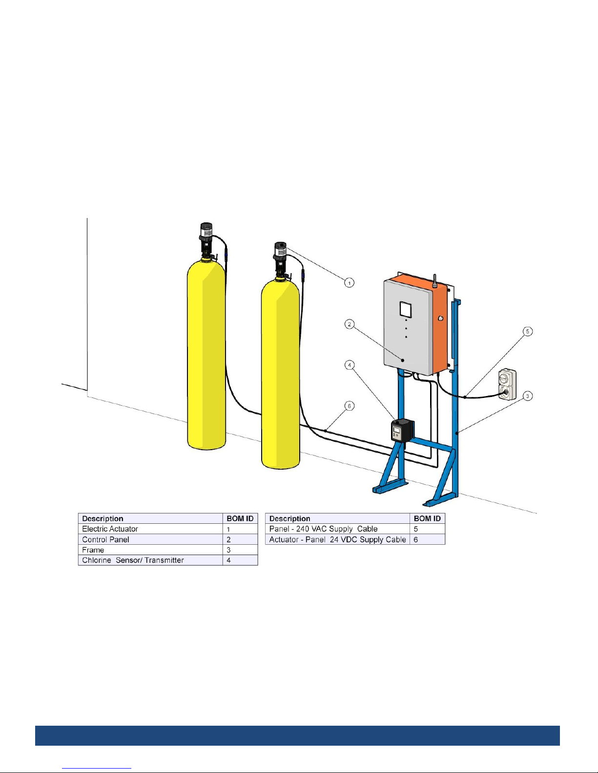
1.1 Typical Setup (70 kg cylinders)
Page 6
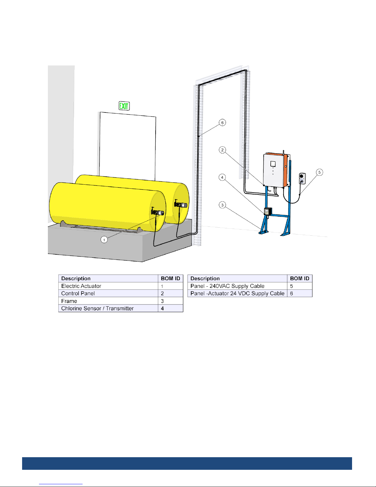
1.2 Typical Setup 920Kg Drums
Page 7
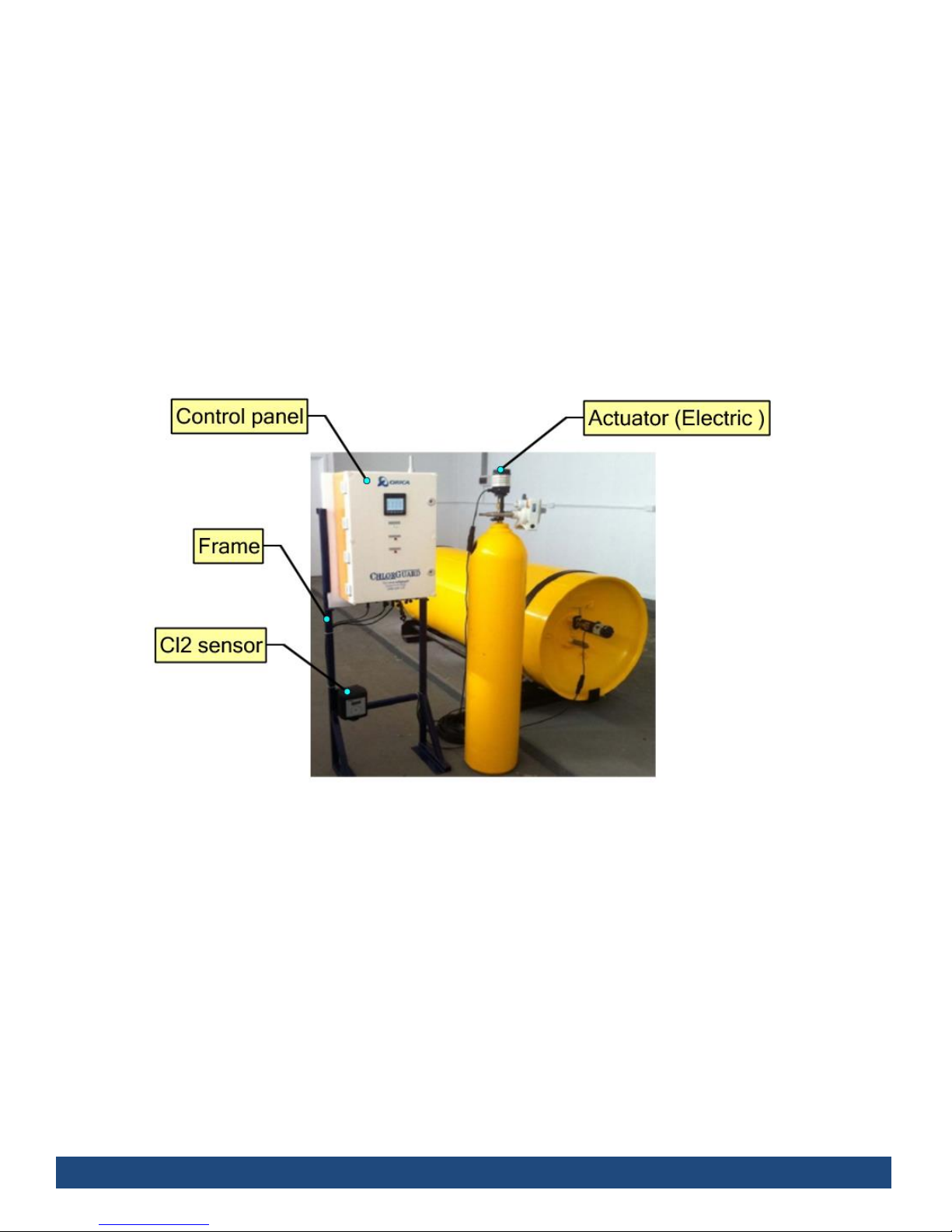
2 KEY COMPONENTS
The chlorguard system includes the following key components
A. Control panel
B. Actuator (Electric or Pneumatic)
C. Cl2 sensor
D. Frame (support of control panel)
E. Air Systems (only if the systems is pneumatic)
F. Support bracket
G. Connecting Transmitting Key
The following chlorguard assembly diagram to ilustrates the main components of the system:
Page 8
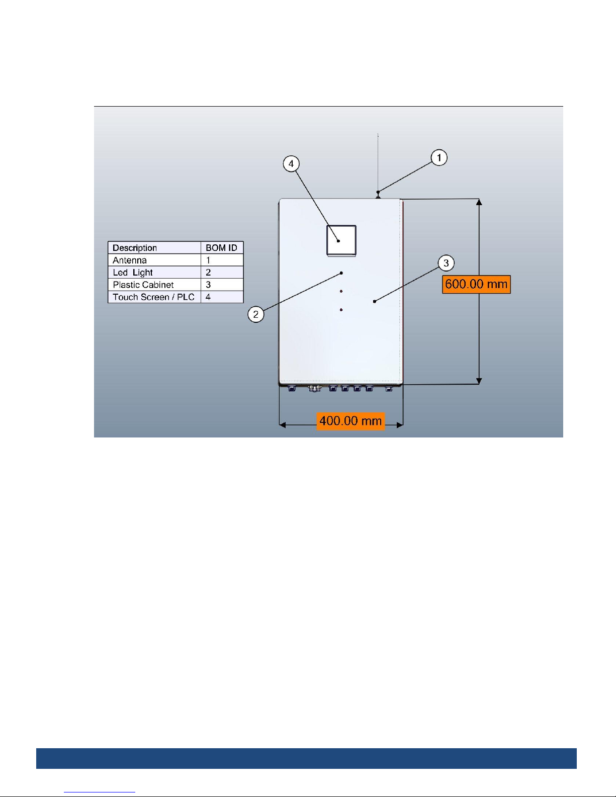
2.1 Control Panel
The Control Panel cabinet includes ports for:
Power
Sensors
Up to 8 Actuators (electrical or pneumatic)
Pneumatic solenoid valve input and output.
External devices (SCADA, Alarms etc.)
The Control Panel internal distribution design differs in the cabinet regarding if the actuator is electric
or pneumatic ; they’re illustrated in the following drawings:
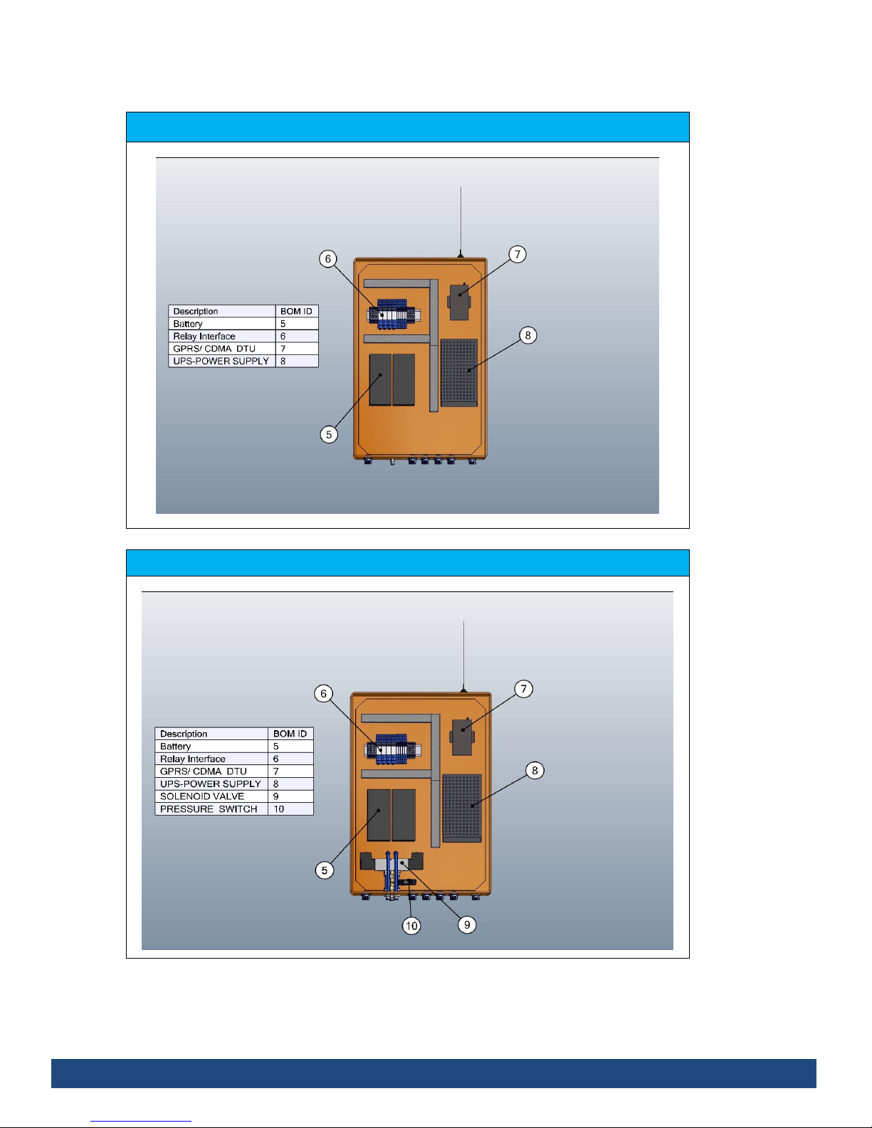
Page 9
Control Panel Electric
Front View
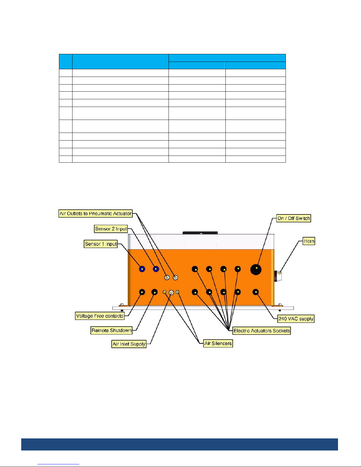
Control Panel Pneumatic
Front View
Page 10
The following are the list of all components inside the cabinet :
Components
Control Panel
electronic
Pneumatic
a
Cabinet-plastic box
b
DC (UPS) power supply
c
PLC (Programable Logic Controller)
d
GMS wireless module
e
Battery
f
Relays (Auxiliary relay, base of the
relay and auxiliary relay)
g
Warning LED’s:
Visual Alarm (3 Flashing light)
h
Connectors (Hearvy load connector)
i
Pressure switch
j
Solenoid Valve
k
Sockets and plugs
The connection points the Control Panel are shown if the diagram below.
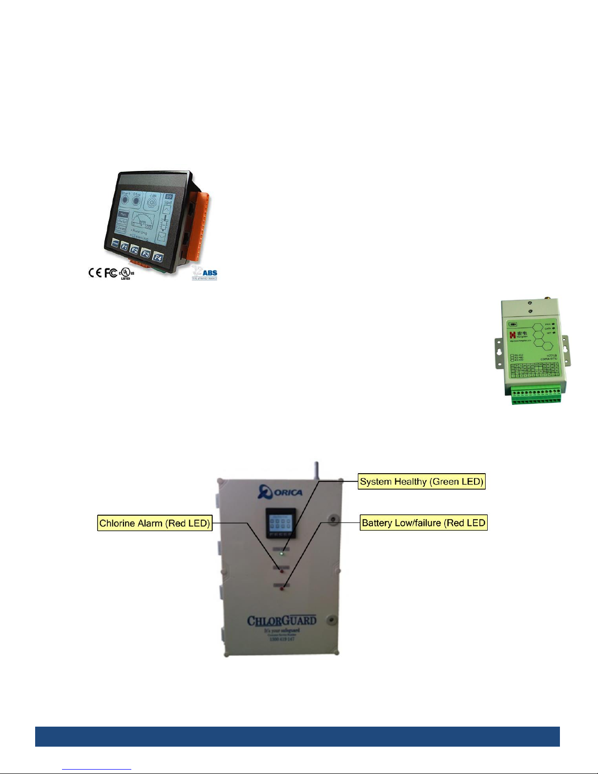
Page 11
2.1.1 DC (UPS) power supply
The DC Uninterrupted Power Supply (UPS) provides reliable 24 VDC Power Supply load to the
ChlorGuard system.
2.1.2 PLC (Programmable Logic Controller)
The ChlorGuard PLC includes a touch screen that provides system
information and access to menus within the program for those
authorised.
2.1.3 GMS wireless module
The GSM transfers information on the status and alarm conditions of the ChlorGuard system for
up to 4 operator phone contacts if required. Important information such as chlorine releases and
alarms are immediately transferred by wireless to operators letting them know when and how
much chlorine is in the work area. Operators can use their phones to log into the ChlorGuard
system to check the status of the system at any time.
2.1.4 Warning LED’s: Visual Alarm
Indicating lights on the front of the panel include the following.
The other indication light such as Low air pressure, etc., is show in the PLC screen.
Page 12
Allowance made to connect up a flashing “Warning Light” and “Audible” alarm connection so the
Customer can connect to.
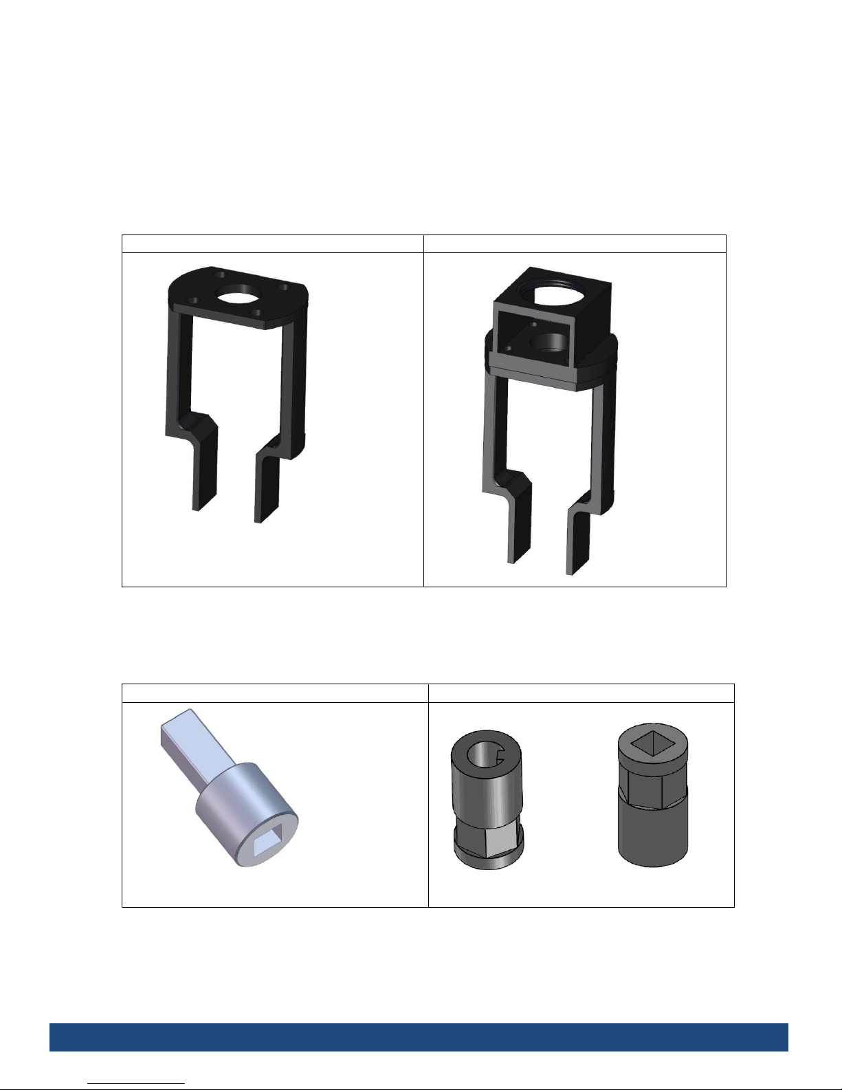
2.2 Support Bracket
The patented support bracket has capability of attachment to both the pneumatic or electric type
actuators and is made from mild steel and powder coated.
Electric Support Bracket
Pneumatic Support Bracket
2.3 Connecting Transmitting Key
A small key which connects the actuator to the valve spindle.
Electric Actuator Key
Pneumatic Actuator Key
 Loading...