

IXL 10174 hotline, 10176 hotline, 10636 classic, 10634 classic, 10646 classic with timer Installation & Operating Instructions Manual
FAX
IXL Appliances NZ Ltd
PO Box 100755,
North Shore Mail Centre, Auckland
0800 806 664
(09) 476 0028
IXL Appliances Service Division
A division of Backwell IXL Pty Ltd ACN 005 326 009
PO Box 818, Geelong, Victoria 3220
1800 032 558
1800 032 024
APPLIANCES
4.5kW
10636 Classic, 10646 Classic with Timer
Models: 10174Hotline, 10634 Classic
6kW Models: 10176 Hotline,
& Classic
Hotline
Installation
Instructions
Semi Recessed
Space HeaterElectric
The benefits conferred by this warranty are in addition to all other rights and remedies in respect of
the product which theconsumer has under the Trade PracticesAct and similar state and territory laws.
Under this warranty, for a period of two years from the date of purchase, IXL Appliances undertake to
replace or make goodany parts which are proven to be defective. The warrantyapplies only if:
1. The unit is installed and used in accordance with the manufacturer ’s instructions.
2. The defects were not caused by changes or modifications made by unauthorised persons.
EXCLUSIONS:
This warranty does not cover damage or loss caused by:
a. Misuse, negligence or faults due to incorrect installation
b. Improper wiring circuits or fuses
c. Attempts to repair the appliance by unauthorised people
d. Failure to install and maintain the appliance in accordance with the manufacturer's instructions.
The benefit conferred by this warranty are in addition to all other rights and remedies in respect of the product
which the consumerhas under the Trade Practices Actand similar state and territory laws.
If the unit failsto function, before calling for service please check the following:
1. Check that switch is ON and neon indicator is glowing
2. Check that the electrical supply is on at the switchboard and the fuse is intact
3. Check that the thermostat is set correctly
Should the unit require service, please contact your nearest IXL Service Centre:
IMPORTANT:The Warranty does not cover service calls related to incorrect operation. Shouldthe unit
require service, switch it offand contact the manufacturer or state distributor.
Warranty
Service
Operation instructions
Manufactured & Warranted by:
BACKWELL IXL Pty Ltd. A.C.N. 005 326 009
Wood Street, East Geelong, Victoria, 3219, AUSTRALIA
Tel:1800 032 558 Fax: 1800 032 024
APPLIANCES
P/No.611131
Safety Information
For safeoperation of your heater,please ensure you observe thefollowing points:
1. Donot cover or obstruct the air vents of the heater.
4. Neverdrape the heater with clothesor other combustible materials.
5. Neveruse the heater in thevicinity of paint thinners, petrolor other combustible liquids.
6. Theheater is not intended foruse by young children orinfirm persons without supervision.
7. Youngchildren should be supervisedto ensure they do notplay with the heater.
8. Do notallow water to splash on the heater. If theheater appears to be dump, do notswitch the power
on.
9. Keep top and bottom air inlet and outlet grilles clear and unobstructed - clean externally with
vacuum cleaner.
2. Donot place any large obstructionswithin 1 metre of thefront of the heater.
3. Donot insert objects through theair vents of the heater.
& Operation
CLEANING AND MAINTENANCE:
To heat one area only adjust rear register chain for one direction only.
Turn thermostat in unheated area to minimum setting. Adjust thermostat in heated area to obtain
desiredtemperature.
Toheat both areas select temperaturerequired in each area. Adjust rear register chainto give balanced
heating. Correct position willbe foundby trial anderror.
When Fitted with Dual Thermostat Only:
(B.V.Models only)
Toobtain heatthrough rear registerdisengage chain andallow chain tobe drawn backinto register. Lock
chainat any desiredposition. When heatingboth mainroom and reararea, useonly "HI" selection.
Warmair can be directedin either orboth directions in anyproportion. To heat main room pull chainin
rearregister outwards tofull extentand lock inposition.
BACK VENT OPERATION:
Simplyswitch off thered illuminatedON/OFF switch. DONOT TURN DOWNTHE THERMOSTAT.
TO TURN THE HEATER OFF:
Switch ON the red ON/OFF switch. To give faster
warmupusing both heatingelements simply
When power is on the ON/OFF switch is illuminated.
switchHI on theHI/LO switch.
Set thermostat to 20°C.
The heater will operate and cycle on and off to maintain steady temperature in the room. Individual
requirements may require adjustments to thermostat setting but for economy use the lowest setting at
whichcomfort is obtained.
When the room has reached comfort level, select "LO" on the HI/LO switch and use this selection
whenever possible for optimum distribution and economy. For best results and comfort, do not sit too
closeto heater orobstruct outletwith furniture.
Note:
The heater will not operate unless the room temperature is below that selected on the thermostat.
TO HEAT:
(i)2 switches onheater controlling:
-ON/OFF switch(red illuminated)
-HI/LO switch (red) which selectsone or bothelements
(ii) Remote thermostat (wall mounted)
CONTROLS:
For satisfactory performance of your IXL electric space heater please read these instructions carefully.
Tosave on running costs you should insulate the ceilings of your home. This will help keep your home
warmin winter andcool insummer.
For additional assistance in the use of your heater contact your electrical authority showroom, the
manufactureror State Distributor.
INTRODUCTION
Additional Warning
Before using your IXL space heater for the first time or if the heater has not been used
recently,the area where the heateris used MUST be well ventilated forat least 2 hours.
As with any new heating appliance, certain effects such as faint odour may occur. These are
part ofthe NORMAL running-in process andwill disappear.
FAX
The only moving part in your heater is the fanunit which is designed for long life. To maximize the life
of the heater we recommend that it be cleaned internally by a qualifiedelectrician/ser vice agent every
two years or asrequired.
: During maintenance and service ensure heateris electrically isolated.IMPORTANT
All external surfaces should be cleanedusing warm water and mild detergent. Donot use abrasives as
scratchingwill occur.
CONGRATULATIONS ON PURCHASING OF BACKWELL IXL ELECTRIC SPACE HEATER
Owners Warranty and Service Record
Complete and keep the following information as it is vital for warranty claims and service calls.
Ensure you maintain proof of purchase including date.
Cat./Model Number ............................................ Serial Number ..........................................................
Date Purchased .......... /................ /............. Installed by ....................................................................
Please read these instructions completely before commencing installation
1. Inspect the heater for damage before proceeding with installation.
2. All models must be installed by a registered electrician.
3. Ensure an isolating switch is incorporated in supply wiring, and that this switch isolates all live
connections to the heater.
4. Unit must be installed in accordance with Wiring Rules AS/NZS 3000:2000.
Installation
Poor
Good
Good
Locating theheater
Chose a location to give good distribution of warm air
through the room. Avoidcorners to allow spread of warm
air (see Fig.1) Do not install close to or directly opposite
furniture,or near curtainsor drapes.
Electrical supply requirements:
Removetwo screws inlower grille.
Using screwdriver through slots in top of front panel,
remove jacknuts and discard angle from two screws
securingfront to topof heater.Check thatfan spinsfreely.
To remove front
Min.Distance between studs393 mm(15 “)(see Fig.2).
Min. depth of stud plus one thickness of wall cladding 88
mm(3 ½").
½
Topof skirtingshould be noless than 60mm (2¼") and no
morethan 100 mm(4") abovefloor covering (seeFig. 3).
Breakplasterboard away frombehind skirtingboard.
Fig. 3
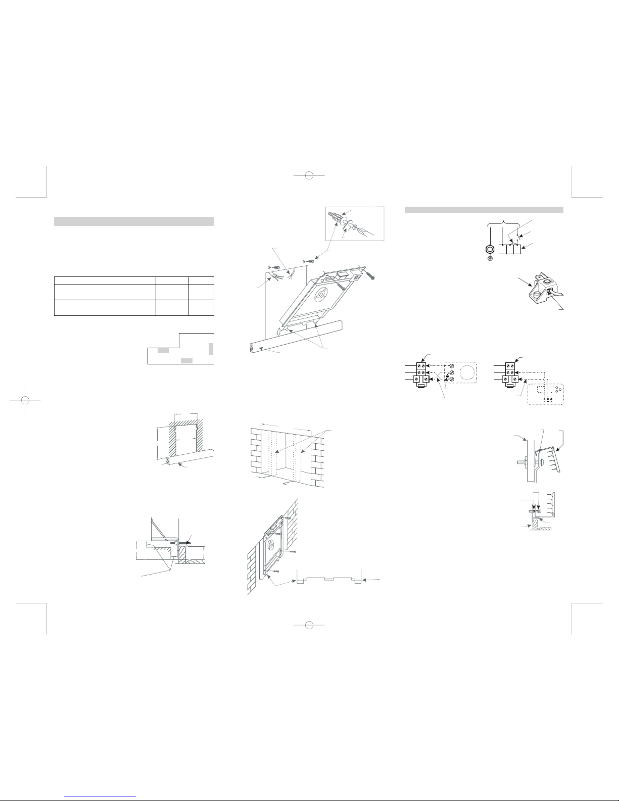
Cavity preparation:
Installation in a stud wall
Clearance between underside ofheater surround and top of floor covering must not beless than 65 mm
(2 “)- see Fig3.½
Important
It is important that a clearance of at least 6
mm (¼") be maintained between the back, side
and top surfaces of the heater rear box ( and
back vent stub if fitted) and the wall cavity into
which it is fitted.
Stand -off spacers are incorporated in the design
to indicate the clearances required.
Clearances
Additionally 25mm (1") to be maintained
between these surfaces and any adjacent
material
415mm
393mm
Skirting board
625mm
Tongues
65 mm min
60 - 100 mm
Thermostat wires
Jacknuts
To set jacknut drill 9.5mm (3/8“) diameter hole in wall
cladding. Push jacknut intohole. Pass metal thread screw
through friction wrench and into jacknut. Hold friction
wrench against jacknut and tighten screw, remove screw,
jacknutremains captive (seeFig.4)
Tongues
Skirting board
Friction wrench
Jacknut in wall
Installation in brick chimney
Cut
832 mm max.
415mm apart
Dummy studs
if required
583 mm min
665 mm max
411 mm min.
If necessary, cut off
2 tabs as shown
Drill flanges and attach screws as required
External wiring:
Isolating switch to be installed in accordance
withclause 4.3.53 ofAS/NZS3000:2000.
A circuit breaker is accepted as an isolating
switch(see Fig. 8).
.
Note: For 2 phase supply remove
bridge between A1 and A2
For thermostat location and installation please refer to thermostat Installation Instructions supplied
withthe thermostat.
For thermostat connectionto the thermostat terminal block refer to Fig.10 (for Models10634, 10636,
1074and 1076) orto Fig.11 for Model10646. Recommended wire1.0mm T.P.S.
2
Thermostat location and installation
Please leave Operation Instructions and Warranty with heater or hand to householder.
Mr INSTALLER
Tocheck operation set thermostatto a setting higherthan room temperature and select"LO" and "ON".
Thefan on lowspeed andone heating elementshould operate.
Then select"HI", the secondelement should beenergized and fanwill run onhigh speed, givingfaster air
flowand higher outlettemperature.
NOTE:When ON/OFF switchis ON,neon glows continuouslyon eitherLO or HI setting.
Check that unit functions
Fix front to heater through lower grille with2 long
metal thread screws, using serrated lock washers.
Tightenall 4 screws(see Fig.12 and 13).
Discardplastic film fromdecal andswitches.
Hook front of heater over lip on upper edge of
heater, making sure switches and decal do not
catchon aperture edge.
Pushtop fully down(see Fig.12).
To fit front to heater
A1 9.5A
A2 9.5A
A1 12.5A
A2 12.5A
A1 19A
A1 25A
240/230 V 50 Hz
Two phase*
Single phase
The terminal block is completed with clamp plate. Please make
sure that wire enters terminal block above the clampplate (see
Fig.9). No contactwill be madeif wireenters below clampplate.
Important
For additional information or name of your nearest agent please phone (03) 5222 2922
Electric cable
HotlineModel 10174 and10176 only.
Cap off chimney to prevent rain entry. Allow some ventilation to prevent dampness. Fix to brick or
alternativelyprovide dummy studs.
Model No.s 10174 and 10634 4.5kW 19A
Model No.s 10176, 10636 & 10646 6kW 25A
*NOTE: For 2 phase supply remove bridge between A1 and A2 (see Fig. 8).
Fig. 2
Fig. 1
Fig.4
Fig. 5.
Fig. 7
Fig. 6
Lowerflange of heaterbehind skirting. Tonguesrest ontop of skirtingboard (see Fig.5). Make electrical
connectionsand tighten ALLterminals.
Fixto wall asindicated, engagingtwo top screwsinto jacknutsbut do notfully tightenat this stage.
To attach heater’s body to wall
Fig. 9
Wallboard
Topedge
of heater
Heater
front
Fig. 12
Skirting board
Rubber
Retaining
Ring
Serratted washer
Tongues
Fig. 13
Connection of thermostat to heater
Model 10646 - Classic with timer
Fig. 11
From thermostat through
hole between relay and
switch bracket
A
B
C
with 2A fuse
Thermostat terminal block
NOTE: Thermostat circuit is protected by 2A fuse which is inserted into the thermostat terminal block fuse
holder.
White
Red
Blue
2A
CLAMP PLATE
NA2A1
Earth
Isolating switch
Connection of power supply for single phase
Power terminal block
Bridge
Fig. 8
Power terminal block
Power supply
Connection of thermostat to heaters
Model No: 10174, 10634, 1063610176,
White
Red
Blue
Capacitor
From thermostat through
hole between relay and
switch bracket
2
1
3
Fig. 10
2A
with 2A fuse
Thermostat terminal block
 Loading...