

EmulationEngine 11a/b/g User's Guide
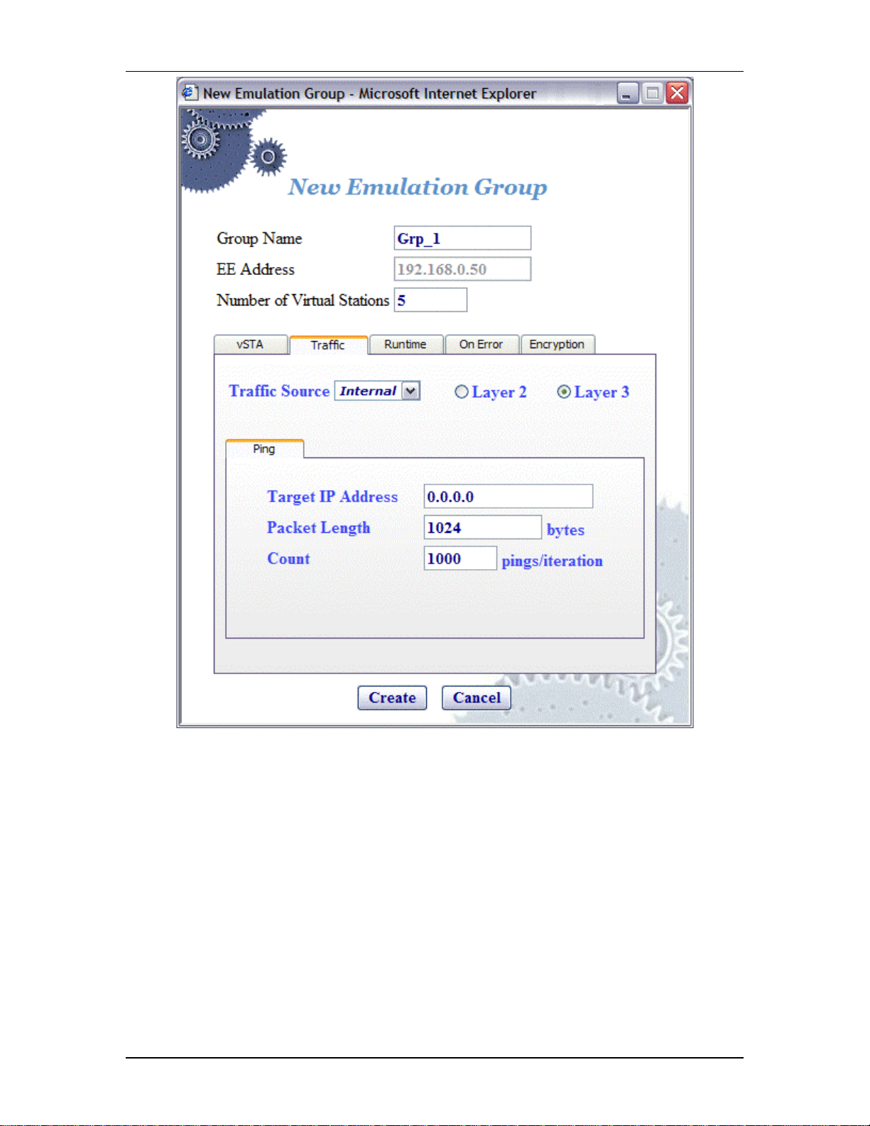
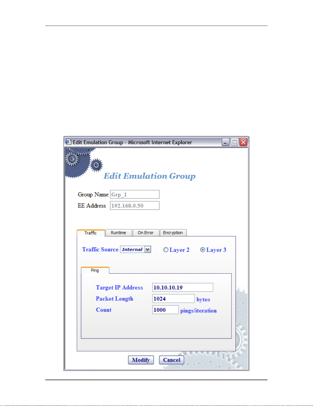
Traffic Source: Select Internal or E xternal from the list box. In Internal
mode, traffic is generated internally by each vSTA us ing ICMP Echo (Ping)
Request/Reply packets. In External mode, packets coming into the
EmulationEngine over 802.3 are mapped to virtual stations by source IP or
MAC address and forwarded via 802.11. Packets coming back via 802.11
are remapped to the originating MAC address.
Layer 2/Layer 3: If External is selected in the Traffic Source field, select
one of these radio buttons to identify the external frames to be captured.
If Layer 2 is selected, frames will b e capt ured based on the source 802.3
MAC address. If Layer 3 is selected, frames will be captured based on th e
source IP address. For vSTAs configured at layer 3, IP and ARP packets
generated from this hos t that contain the virtual station's IP address as a
source will be translated at the MAC layer to appear as if sourced from the
virtual station's MAC address.
Target IP Address: Enter the target IP address where ICMP Echo (Ping)
Requests should be sent. The default IP address (0.0.0.0) shown in this
080104 5-25
Communication Machinery Corporation (CMC)
example dialog must be replaced by a valid IP address (e.g.,
10.10.10.19).
Packet Length: Specify the size of the ping data buffer (64...1024). The
default is 1024.
Count: Specify the total number of pings to be sent: 0.. .10000 (0=None).
!"
Click “Create” to create the group.
!"
Click “Cance l” to exit this d ialog.
vSTA->New Group->Runtime
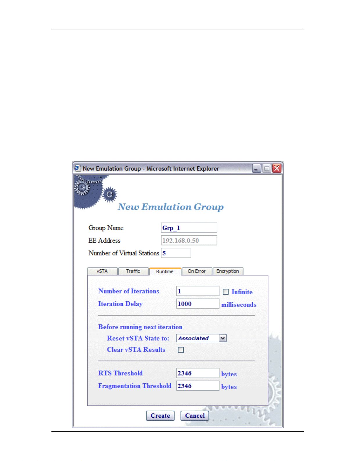
The Runtime section of the New Emulation Group dialog allows you to run
a virtu al station’s t est multiple times. This is only applicable to internal
traffic generation. After each iteration of a test, the state of the virtual
station can be set to a “base state”. A user-defined delay between
successive iterations is defin ed in milliseconds. Op tionally, any r esults
collected for the virtual station can be cleared at the start of each
iteration.
5-26 080104

EmulationEngine 11a/b/g User's Guide
Number of Iterations: Enter the number of times (1...10000) to repeat
the virtual station’s task (Ping) or select the Infinite checkbox to
continuously iterate indefinitely.
Iteration Delay: Enter the delay (in milliseco nds) to be introduced
between iterations of the test. It can be set to a value in the range:
0...300000 milliseconds (5 minutes).
Before Running Next Iteration->Reset vSTA State to: Select a state
from the list box. Each virtual station in this group will be reset to t he
selected state (initialized, authenticated, or associated) at the end of
each iteration.
Before Running Next Iteration->Clear vSTA Results: Select this
check box to clear test results before successive iterations of the test.
RTS Threshold: Enter a value in the range 1...2346 to define the RTS
threshold for the virtual station(s) in this group. Any frame to be
transmitted by a virtual station that exceeds the RTS threshold, will
require a successful RTS/CTS frame exchange before the frame is
transmitted. The minimum value (1) effectively requires RTS/CTS fo r all
transmit frames. The maximum value (2346) is the maximum 802.11
frame size and effectively disables RTS.
Fragmentation Threshold: Enter a value in the range 256...2346 to
define the fragmentation thres hold for the virtual station(s) in this group.
The fragme ntation threshold will lim it the number of bytes in any 802.11
frame transmitted by the virtual station(s). If this field is set to 2346 (i.e.,
the maximum 802.11 frame size), fragmentation is effectively disabled.
!"
Click “Create” to create the group.
!"
Click “Cance l” to close this dialog .
vSTA->New Group->On Error
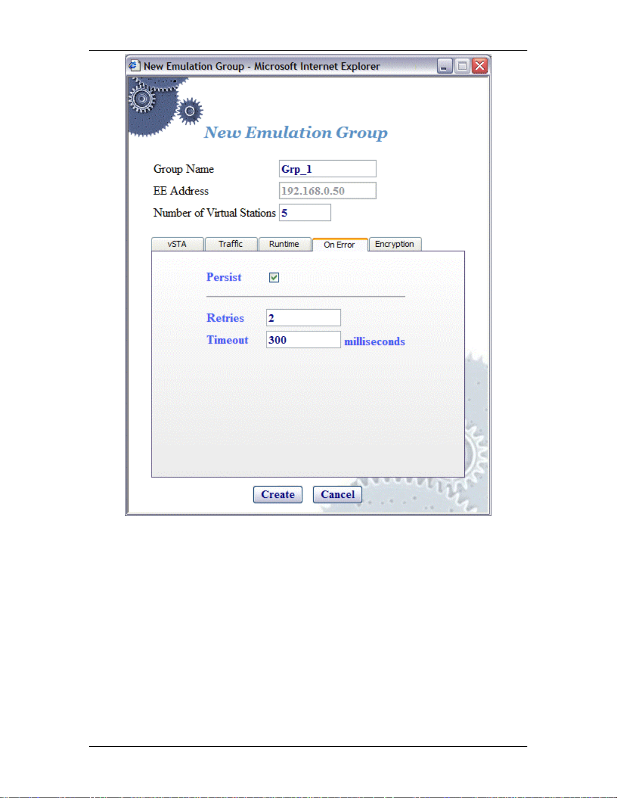
The On Error section of the New Emulation Group dialog defines whether
virtual stations should reconnect to the System Under Test during a test if
the system de-authenticates or disassociates a virtual station.
080104 5-27
Communication Machinery Corporation (CMC)
Persist: Select this checkbox to e nable o r disable persistence. When
enabled, vir tual stations in this group will r emain persistent (connected) if
the System Under Test de-authenticates or disassociates. If the
EmulationEngine loses connection to a System Under Tes t, persistence will
allow it to recover and continue the test at the point where it was
interrupted. For example, if a virtual station is in a run or associated state
and an 802.11 management frame (deauth or disasso c) is sent by the
System Under Test and received by the EmulationEngine, the virtual
station will attempt to return to the state it was in before the
management frame was received. If the virtual station was running a ping
test, the pin g test will cont inue. If it was in an associa ted state, the virtual
station will reissue the associat e req uest.
Retries: This field sp ecifies the n umber of times the EmulationEngine
should issue authentication and association requests bef ore failing the
operation. It can be a value in the range 0...10.
5-28 080104
EmulationEngine 11a/b/g User's Guide
Timeout: This field specifies the timeout value (in millise conds) for
authentication and association requests. It can be set to a value in the
range 250...60000 milliseconds (1 minute).
!"
Click “Create” to create the group.
!"
Click “Cance l” to close this dialog .
vSTA->New Group->Encryption
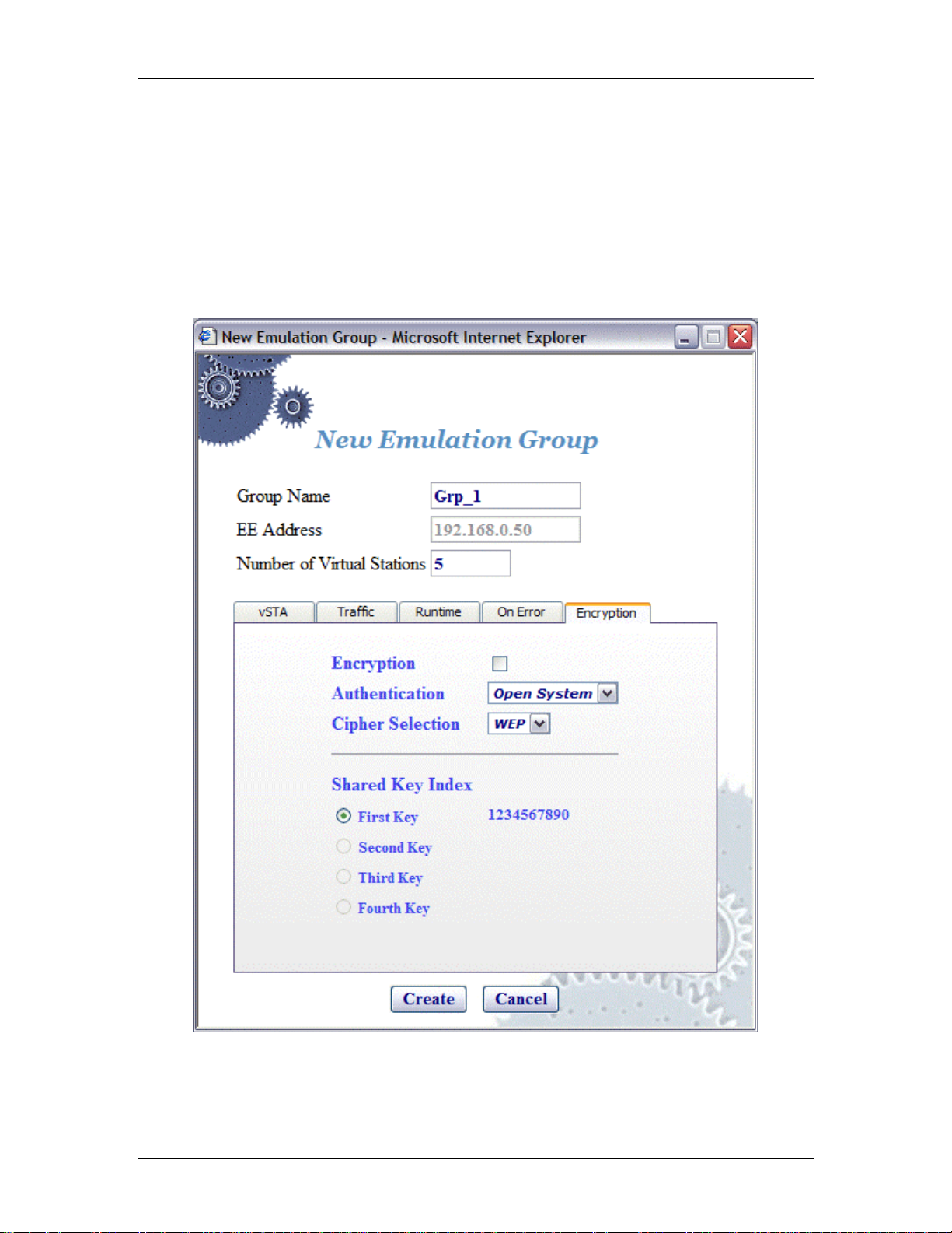
This section of the New Gro up dialog defines whether the virtual station
will use encryption, the associa ted cip her to be used and t he type of
authentication (Open System or Shared Key) to be used for authenticating
with the System Under Test.
NOTE: The four shared keys for Wired Equivalency Privacy (WEP)
encryption must be defined in the Encryption Def aults dialog in the
Configuration side bar.
Encryption: Select this checkbox to ena ble/disable encryption.
080104 5-29
Communication Machinery Corporation (CMC)
Authentication: Select the authentication type: Open System or Shared
Key.
Cipher Selection: Reserved for future use. WEP is the only supported
selection in this release.
Shared Key Index: This section of the dialog will show the shared keys
that were defined in the Encryption Default dialog. See "Configuration>Encryptio n". Select th e shared key to be used. These keys will be used
for encryption by virtual stations in this scenario group with the System
Under Test.
!"
Click “Create” to create the group.
!"
Click “Cance l” to close this dialog .
vSTA->Edit Group
The following dialog is displayed when the Edit Group button is selected in
the vSTA side bar.
5-30 080104
This dialog is the same as "vSTA->New Group" dialog except it does not
have a vSTA tab. After virtual stations have been created, MAC and IP
Addresses cannot be changed. See "vSTA->New Group" for a description
of the fields in this dialog.
!"
Click “Modify” to modify all virtual stations with t he new settings.
!"
Click “Cance l” to close this dialog without modifying any virtual stations.
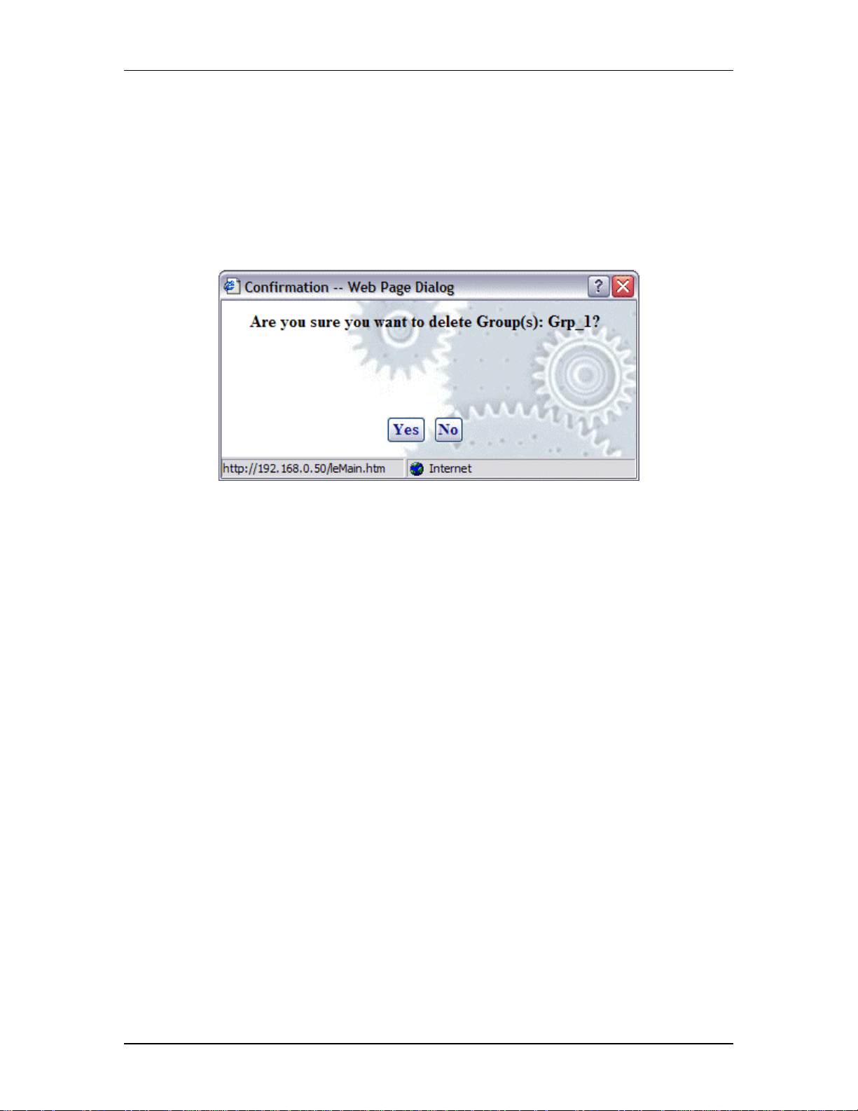
vSTA->Delete Group
When the Delete Group button is selected from the vSTA side bar, a
confirmatio n dialog will ask you to confirm this selection.
EmulationEngine 11a/b/g User's Guide
!"
Click “Yes” to remove the group and all virtual stations in it from the
system.
!"
Click “No” to close this dialog without removing the group.
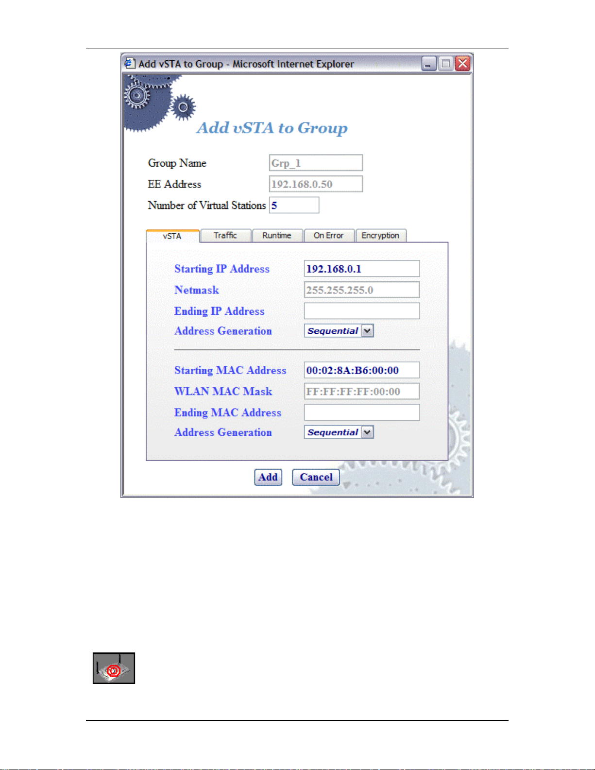
vSTA->Add New vSTA to Group
The following dialog is shown when the Add New vSTA to Group button is
selected in the vSTA side bar.
080104 5-31
Communication Machinery Corporation (CMC)
This dialog is used to add new virtual stations to an existing scenario
group. All fields in this dialog default to the values that have were initially
entered when the group was created. Any changes to this dialog will also
update these group default values. See "vST A->New Group" for a
description of the fields in this dialog.
!"
Click “Add” to add the virtual station.
!"
Click “Cance l” to close this dialog .
EE (EmulationEngine) Side Bar
The buttons in this side bar are used to configure and manage the
EmulationEngine and to select and join with a System Under Test.
Select SUT: Click this button in the EE side bar to display the Select
System Under Test dialog.
5-32 080104
Join SUT: Click this button in the EE side bar to join with the System
Under Test.
Configure EE: Click this button in the EE side bar to configure the
EmulationEngine.
Reconnect EE: Click this button in the EE side bar to reconnect to the
EmulationEngine. This is used after a reboot of the EmulationEngine.
Reset EE: Click this button in the EE side bar to reset all statistics
counters to zer o and all virtual stations to a configured state.
Reboot EE: Click this button in the EE side bar to reboot the
EmulationEngine.
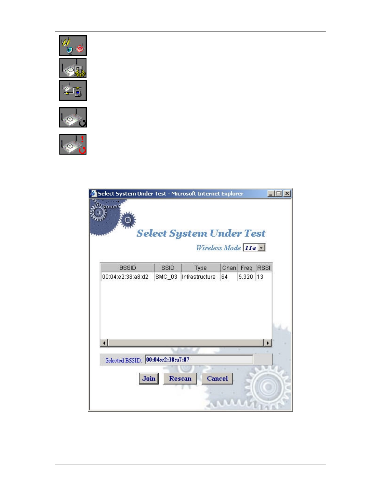
EE->Select SUT
When the Select SUT button is selected in the EE side bar, the Select
System Under Test dialog is displayed:
EmulationEngine 11a/b/g User's Guide
Wireless Mode: This field shows the EmulationEngine’s current wireless
mode (11a, 11b, or 11g). You can select a different wireless mode from
the list box. The web-based user interface will issu e a command to the
EmulationEngine to change its wireless mode and scan for compatible
systems. The results of the new scan will be reflected in the BSSIDs in the
list box.
080104 5-33

Communication Machinery Corporation (CMC)
!"
Click o n a BSSID in the list box.
!"
Select “Join” to join with the selected System Under Test.
!"
Selec t “Rescan” to update the list of BSSIDs. This selection will cause the
EmulationEngine to scan for Basic Service Set IDs and update the list of
available systems.
!"
Click “Cancel” to close this dialog without selecting a System Under Test.
If a scenario with virtual stations already exists and you have previously
joined with a system , the following dialog will be displayed if you select a
different BSSID in the Select System Under Test dialog:
!"
Click “Yes” to continue and join with a different System Under Test.
!"
Click “No” to return to the Select System Under Test dialog.
EE->Join SUT
When the Join SUT button is selected in the EE side bar, a confirmation
dialog is displayed:
!"
Click “Yes” to join with the System Under Test.
!"
Click “No” to cancel this operation.
EE->Configure EE
The Configure EmulationEngine dialog is a tabbed dialog that defines the
interaction with the web-based user interf ace and EmulationEngine
operational parameters.
EE->Configure EE->UI
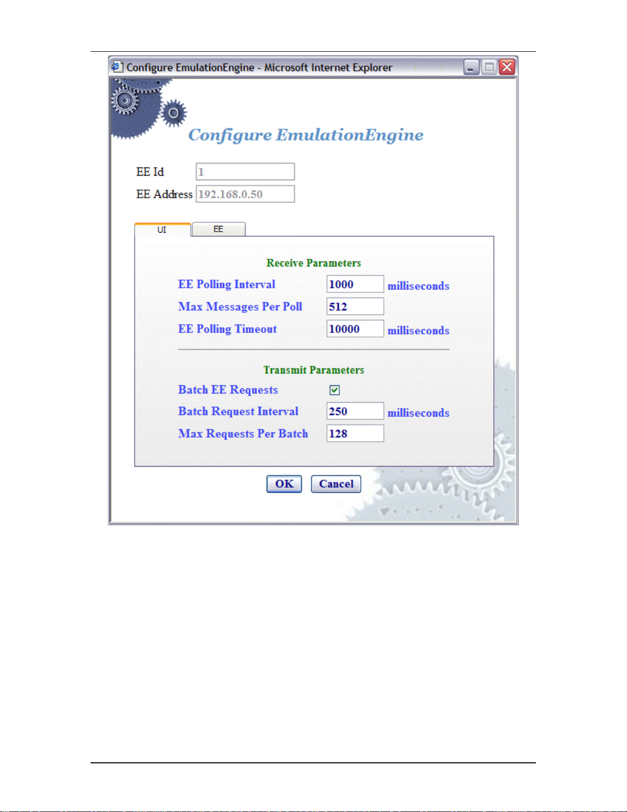
When the Configure EE button is selected in the EE side bar, the Configure
EmulationEngine dialog is displayed:
5-34 080104
EmulationEngine 11a/b/g User's Guide
EE Id: This field is set by the system and canno t be changed.
EE Address: This field shows the EmulationEngine's IP address.
Receive Parameters
EE Polling Interval: This entry defines t he interval (in milliseconds) that
the Command PC will poll the EmulationEngine for command and control
messages from the virtual stations. It can be set to a value in the range:
250...60000 milliseconds (1 minute). If this time expires without an
expe cted response from th e EmulationEn gine, the user interface will
display "Busy" next to the EmulationEngine icon in the toolbar. The "Busy"
message indicates that the EmulationEngine is not responding to the user
interface. Under normal conditions, the "Busy" message may appear
periodically for short periods of time. If the “Busy” message appears
freq uently, you may want to increase the value assigned to the EE Polling
Interval. Also see Chapter 9, Troubleshooting/EmulationEngine Busy or
Not Responding.
080104 5-35

Communication Machinery Corporation (CMC)
Max Messages Per Poll: Specify the maximum number of messages to
receive in each poll: 1...128.
EE Polling Timeout: This entry defines t he time (in milliseconds) that
the Command PC will wait for a resp onse from the EmulationEngine. It
can be set to a value in the range: 500...120000 milliseconds (2 minutes).
The recommended value is two t imes the EE Polling Interval value. If this
time expires without an expected response from the EmulationEngine, the
user interface w ill display a dialog indicating that th e EmulationEngine is
not responding. When you dismiss the dialog, the status of the
EmulationEngine/System Under Test c onnection in th e toolbar will display
“Off line”. If this dialog and “Offline” status appears fr equently, a larger
value should be assigned to the EE Polling Timeo ut. Also see Chapter 9,
Troubleshooting/EmulationEngine Busy or No t Responding.
NOTE: Also see the Monitor Update Interval and Monitor Update Timeout
in Monitors->Config Monitors for the interval and update timeout values
that are used by the command PC to collect statistics values.
Transmit Parameters
Batch EE Requests: This checkbox enables/disables batching of r equest
messages to be sent to the EmulationEngine. When virtual stations are
running in an iterative fashion or you issue commands to many virtual
stations, this will produce a large number of r equests to the we b server on
the EmulationEngine. Request batching will maintain a numbe r of these
requests over a period of time (defined by the Batch Reques t Interval)
and then issue one large reque st with all pending instructions.
NOTE: If you are currently running or intend to run a Load Prof ile,
batching EE requests may affect the timing of the Load Profile if the Batch
Request Interval is greater than the timing specified in the Load Profile.
Batch Request Interval: If "Batch EE Requests" is checked/enabled,
specify the interval at which the web-based user int erface will collect
(batch) requests and send them to the EmulationEngine. It can be set to a
value in the range: 250...60000 milliseconds (1 minute).
Max Requests Per Batch: Specify the maximum number of requests
that should be batched before they are sent to the virtual stations. When
this num ber of requests have been batched , they will be sent to the
EmulationEngine even if the Batch Request Interval has not expired.
!"
Select the EE tab to define other EmulationEngine's configuration
parameters.
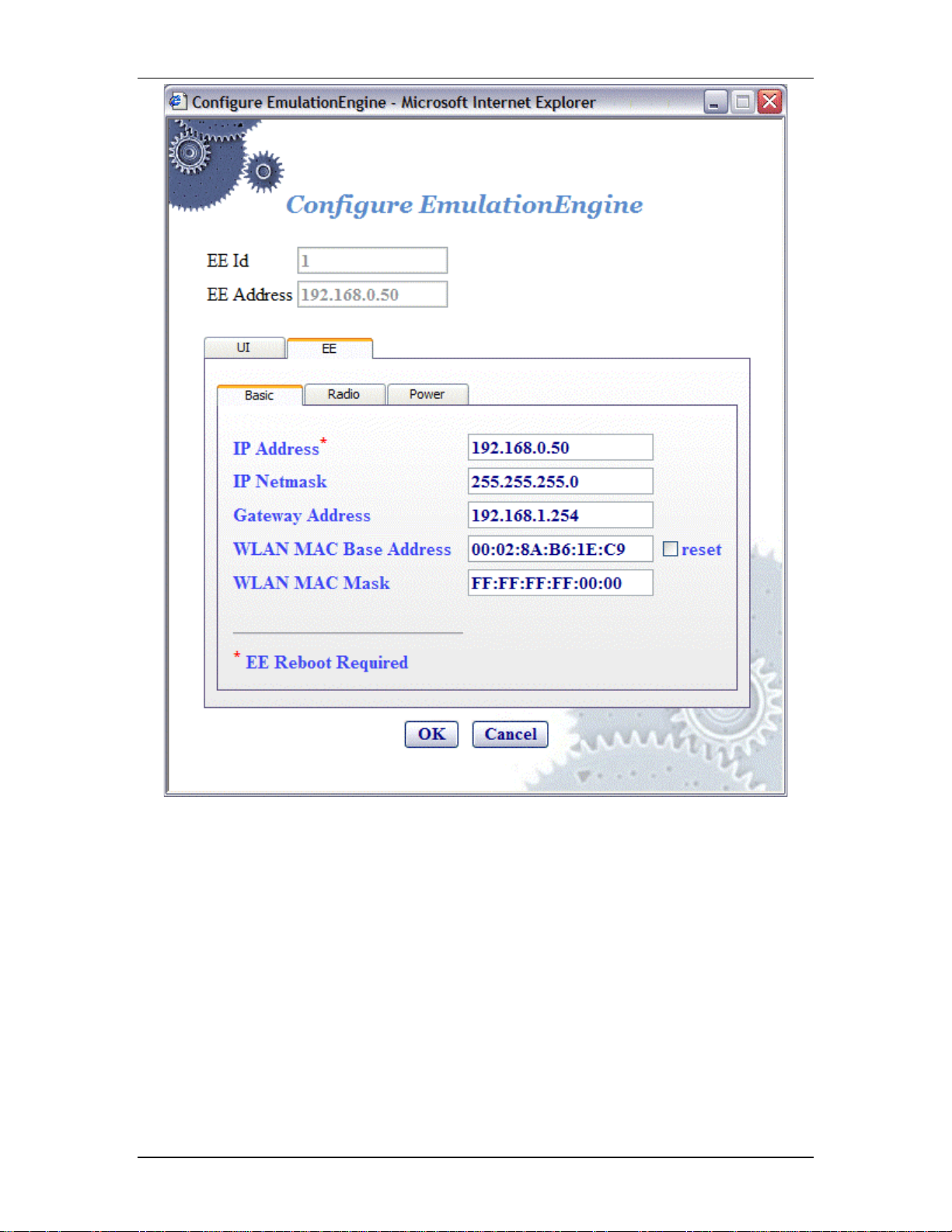
EE->Configure EE->EE/Basic
This section of the Configuration EmulationEngine dialog defines the basic
configuration of the EmulationEngine.
5-36 080104
EmulationEngine 11a/b/g User's Guide
EE Id: This field is set by the system and canno t be changed.
EE Address: This field shows the EmulationEngine's current IP address.
IP Address: Enter the EmulationEngine's new IP address. Use a dot IP
address (e.g., 192.168.0.50). If you change this field, you must select the
Reboot option from the EE sidebar in order for the new IP Address to be
recognized and used in the EmulationEngine.
IP Netmask: Enter the EmulationEngine's network mask. The network
mask of the EmulationEngine must match the IP subnet addressing
scheme for internal mode te sting (it is not used for external mode). For
example, if the EmulationEngine's IP address is 10.1.40.18 and the
system being tested is 10.1.35.17, then the subnet mask is 16 bits or
255.255.0.0.
NOTE: If you change the IP Address of the EmulationEngine and reboot,
the web client does not automatically change its EmulationEngine IP
address. You will need to do it manually. You will need to restart the web
browser after the EmulationEngine has rebooted .
080104 5-37

Communication Machinery Corporation (CMC)
Gateway Address: Enter the EmulationEngine's default gateway IP
address. Use a dot IP address (e.g., 192.168.0.50).
WLAN MAC Base Address: The Wireless LAN MAC address defaults to a
specific address (typic ally in the 00:0b:cd:xx:xx:xx
range). It is a globally unique MAC address that is programmed in to the
EmulationEngine hardware. The address can be changed to any nonbroadcast or non-multicast valid MAC address. If you use multiple
EmulationEngine's at your facility, each should have a WLAN MAC wh ose
prefix is unique. For example, on the first EmulationEngine, use WLAN
MAC Address: 04:0d:e0:62:23:57 and on the second EmulationEngine,
use WLAN MAC Address: 06:0f:14:62:32:a0.
WLAN MAC Mask: This address is used in conjunction with the WLAN
Base MAC Address for configuration of virtual stations. If for example, the
WLAN MAC is set to 00:0b:cd:59:23:44 and the mask is set to
ff:ff:ff:ff:00:00, the only MAC addresses that can be detected on WLAN
and received by the EmulationEngine are: 00:0b:cd:59:00:00 00:0b: cd:59:ff:ff. All ot her MAC addresses will be filtered out. The mask
limits the range of MAC addresses that are assigned to virtual stations.
The mask that is specified here will be displayed in the WLAN MAC Mask
field when the vSTA tab is selected in the New Emulation Group dialog
(See vSTA->New Group->vSTA).
!"
Click “OK” to save this configuration.
!"
Click “Cance l” to close this dialog .
EE->Configure EE->EE/Radio
This section of the EE->Conf igure EE dialog defines the wireless mode and
data rate of the EmulationEngine.
5-38 080104

EmulationEngine 11a/b/g User's Guide
Wireless Mode: Select a wireless mode (11a, 11b, or 11g) from the list
box. The items that are available in this lis t box will be different dep ending
on the feature set that you ordered from CMC. The wireless mode also
affects the types of devices the EmulationEngine can discover during a
scan operation. See the General Usage Notes in Chapter 1.
Data Rate: Select a data rate from the list box. The rates that are
available in this list box will be different dep ending on the Wireless Mode
selection.
!"
Click “OK” to save this configuration.
!"
Click “Cance l” to close this dialog .
EE->Configure EE->EE/Power
This section of the Conf iguration EmulationEngine dialog defines the power
configuration of the EmulationEngine.
080104 5-39

Communication Machinery Corporation (CMC)
Transmit Power: Select full, half, quarter, eighth, or minimum from the
list box.
Selection Description
full maximum (normal) transmit power (18 dBm/64 mW)),
half fractional (1/2) transmit power (15 dBm/31.5 mW),
quarter fractional (1/4) transmit power (12 dBm/16 mW),
eighth fractional (1/8) transmit power (9 dBm/8 mW),
minimum minimum transmit power (3 dBm/2 mW).
If you change the transmit powe r setting, you must select the Reboot
option from the EE sidebar in order for the new trans mit power to be
recognized and used in the EmulationEngine.
Power Management Mode: Select “active” (always a wake) or “power
save” (doze for the specified listen interval) from the list box. See the
notes below.
5-40 080104

EmulationEngine 11a/b/g User's Guide
Power Save Listen Interval: Specify the listen interval in terms of the
number of beacons (1... 100). The default value is 1. See the notes below.
!"
Click “OK” to save this configuration.
!"
Click “Cance l” to close this dialog .
NOTES:
When Power Management mode is set to “active”, the EmulationEngine
will remain in the awake state at all times. When the Power Management
mode is set to “power save”, the EmulationEngine will enter a dozing state
until it is awakened by the listen interval. When dozing:
!"
The Emulation Engine will not accept WLAN frames transmitted to an y
vSTA.
!"
The Emulation Engine will awaken at each list en interval to receive th e
next beacon and poll for frames buffered for any vSTA in accordance with
802.11 Power Management requireme nts.
!"
The Emulation Engine will awaken at DTIM intervals to r eceiv e DTIM
beacons when buffere d broadcast/multicast frames are indicated.
While in either state, any WLAN frames to be transmitted from any vSTA
may be immediately placed into the Transmit Queue for transmission by
the WLAN interfac e. Any transmission from any vS TA will indicate the
EmulationEngine’s current Power Management mode.
The beacon interval is determined by the System Under Test, usually by
some user-configurable parameter. The EmulationEngine receives beacons
that are sent by the System Under Test. A typical beacon rate is one ever y
100 Time Units. An 802.11 Time Unit is defined as 1024 microseconds.
So, the beacon rate would be one every 102.4 milliseconds, or a bout 10
per second. As an ex ample, if the Power Management Mode is set to
Power Save and the Power Save Listen I nte rval is set to 3, the
EmulationEngine will wake up about every 307.2 milliseconds to poll for
frames queued in the System Under Test.
EE->Reconnect EE
Reconnect is required af ter reboot or if yo u become disconnected from the
EmulationEngine for any reason. When the Reconnect EE button is
selected in the EE side bar, a conf irmation dialog is displayed:
!"
Click “OK” to reconnect to the EmulationEngine.
!"
Click “No” to cancel the reconnect selection.
080104 5-41

Communication Machinery Corporation (CMC)
Following successful reconnect, the web-based user interface will restore
the scenario (if any) in the EmulationEngine.
EE->Reset EE
When the Reset EE butto n is s elected in the EE side bar, a co nfirmation
dialog is displayed:
!"
Click “Yes” to reset all virtual stations to a configured s tate and to reset all
statistics counters to zero.
!"
Click “No” to cancel the reset selection.
EE->Reboot EE
When the Reboot EE butto n is s elected in the EE side bar, a co nfirmation
dialog is displayed:
!"
Click “No” to cancel the reboot operation.
!"
Click “Yes” to reboot the EmulationEngine. When Yes is selected, the
follow ing dialog is displayed:
5-42 080104

EmulationEngine 11a/b/g User's Guide
Monitors Side Bar
The Monitors side bar is used to define, delete, clear, export, and
configure monitors. After a monitor is defined using New Monitor, the
bottom sec tion of the main page will show statistics counters.
New Monitor: Select this button to define a new monitor. You ca n
define up to four different monitors in each scenario.
Delete Monitor: Select this button to delete the currently displayed
monitor.
Clear Monitor: Select this button to clear the statistics counters in the
currently displayed monitor.
Export Monitor: Select this button to export the statistics counters for
one or more monitors.
Config Monitors: Select this button to configure how mo nitors are
maintained and updated with data from the EmulationEngine.
A monitor is one or more user-selected statistics co unters that the webbased user interface will collect from the Emulatio nEngine and dis play in
the user-selected f ormat (i.e., line graph, bar graph or table). All data
collected can be exported. Monitors are based on Line graphs, Barographs
and Tables. You can use these to monitor the summary statistics of the
EmulationEngine or a summary “Master vSTA” that shows virtual station
statistics across all virtual stations.
NOTES:
1) Each scenario can include up to four different monitors.
2) Monitor values are stored in memory on the command PC. If you run
one or more monitor s for an extended period of time, available memory
may become depleted and this can affect the performance of the
command PC.
Monitors->New Monitor
The New Monitor dialog is a tabbed dialog that can be used to define
predefined, summary, and summary virtual station counters to be
maintained during the execution of a test.
Monitors->New Monitor->Predefined
Use the Predefined section of the Define New Monitor dialog to select
predefined statistics counters.
080104 5-43

Communication Machinery Corporation (CMC)
Monitor Name: Enter a monitor name. It can be up to 12 characters
(a...z, 0..9, and underscore (_)).
EE Address: This field shows the EmulationEngine's IP address.
Display Style: Select a display style from the list box. It can be one of
the following: Line Graph, Bar Graph, or Table.
Monitors->Selected Monitors: Selec t one of the monitors to be
maintained. Use the [>>] button (or double-click the line item) to transfer
the predefined monitor to the Selected Monitors column. See "Chapter 8,
Statistics Counters" for a description of each of these statistics counters.
!"
Click “Create” to create and display the monitor.
!"
Click “Cance l” to close this dialog .
Monitors->New Monitor->Summary
Use the Summary section of the Define New Monitor dialog to select
summary statistics counters.
5-44 080104

EmulationEngine 11a/b/g User's Guide
Summary Counters->Selected Counters: Select one or more of the
counters to be maintained in the test re sults file. Use the [>>] button to
transfer the counters to the Selected Counters column. See "Chapter 8,
Statistics Counters" for a description of each of these statistics counters.
!"
Click “Create” to create and display the monitor.
!"
Click “Cance l” to close this dialog .
Monitors->New Monitor->vSTA
Use the vSTA section of the Define New Monitor dialog to select the
master (summary) virtual station statistics counters.
080104 5-45

Communication Machinery Corporation (CMC)
vSTA (s): Select a virtual station from the list box. The Master Station is
a summary that shows virtual station statistics across all virtual stations.
vSTA Counters->Selected Counters: Select one or more of the
counters to be maintained in the test re sults file. Use the [>>] button to
transfer the counters to the Selected Counters column. See "Chapter 8,
Statistics Counters" for a description of each of these statistics counters.
!"
Click “Create” to create and display the monitor.
!"
Click “Cance l” to close this dialog .
When you select one or more counters and choose the Create button, the
bottom half of the screen will show the current results in the selected
display style. Example:
As you run scenar io tests, the monitors will be upda ted with curr ent data
from the EmulationEngine. For chart display styles, the legends on the
right side of the monitor indicate the statistics counters selected in the
5-46 080104

New Monitor dialog. For table display styles, the table headings indicate
the statistics counters selected in the New Monitor dialog. See "Chapter
8, Statistics Counters" for a description of each of these statistics
counters. The to olbar buttons on the right-side of the mo nitor display can
be used for the following functions:
Create a New Monitor
Delete the currently selected monitor.
Run a monitor.
Pause a monitor.
Reset a monitor.
See "Monitor Toolbar Buttons" for more information about these buttons.
Monitors->Delete Monitor
When the Delete Monitor button is selected in the Monitors side bar or the
monitor toolbar, a confirmation dialog is displayed.
EmulationEngine 11a/b/g User's Guide
!"
Select “Yes” to delete the current monitor.
!"
Select “No” to cancel the delete selection.
Monitors->Clear Monitor
When the Clear Monitor button is selecte d in the Mo nitors side bar or the
monitor toolbar, a confirmation dialog is displayed.
080104 5-47

Communication Machinery Corporation (CMC)
!"
Selec t “Yes” to clear the monitor. This will set all counters in the monitor
to zero. Statistics gathered up to this point are not cleared an d are still
exportable.
!"
Select “No” to close this dialog without clearing the monitor.
Monitors->Export Monitor
This function is used to export the collected statistics in a defined monitor.
For export, the data obtained from the monitor is saved.
NOTE: For all graphs, each tick saves the information of each field that is
requested. This can gr ow large depending on how long the monitor has
run. An artificial limit of one hour has been enforced to clear this saved
data. At the end of each hour, this stored data array is cleared.
When the Export Monitor button is selected in the Monitoring side bar, the
Export Monitor dialog is displayed:
Select one or more monitors in the list box.
!"
Select “Export” to export the monitors in the Selected Monitors list box.
!"
Select “Cancel” to close this dialog without exporting monitors.
When the Export button is selected, a Save HTML Document dialog is
displayed:
5-48 080104

EmulationEngine 11a/b/g User's Guide
Identify the name of the file where the monitor information is to be
written.
!"
Selec t “Save” to save t he information in to the specified file.
!"
Select “Cancel” to exit this dialog without exporting any data.
Monitors->Config Monitors
When the Config Monitors button is selected in the Monitors side bar, the
Configure Monitors dialog is displayed.
EE Address: This field shows the IP address of the EmulationEngine.
Monitor Update Interval: This entry defines the interval (in
milliseconds) that the Command PC will poll the Emulat ionEngine for new
statistics counters. It can be set to a value in the range: 250...60000
milliseconds (1 minute ). Any value under 1000 millisecon ds is not advis ed
080104 5-49

Communication Machinery Corporation (CMC)
and may affect performanc e significantly. If you notice issues with update
performance, try increasing this value.
Monitor Update Timeout: This entry def ines the time (in milliseconds)
that the Command PC will wait for a response from the EmulationEngine.
It can be set to a value in the range: 500...120000 millis econds (2
minutes). The recommende d value is two times the Monitor Update
Interval value. If this time expires without an expected response from the
EmulationEngine, the user inter face will attempt to resta rt the monitor
update timer.
NOTE: Also see the EE Polling Interval and EE Polling T imeout in EE>Configure EE for the interval and update timeout values that are used by
the command PC to send command and control information to the
EmulationEngine.
!"
Selec t “OK” to save this monitor configurat ion.
!"
Select “Cancel” to close this dialog.
Event Log Side Bar
The buttons in the Event Log side bar are used to display, clear, export,
and configure the Event Log:
Event Log: Select this button to display the last 400 event log entries.
Clear Log: Select this button to clear the cur rent contents of the event
log.
Export Log: Select this button to export the last 400 ev ent log entries to
a file.
Configure Log: Select this button to configure event logging.
Also see "Chapter 7, Eve nt Logging" for more information about how the
EmulationEngine creates and maintains the event log.
Event Log->Event Log
When the Event Log button is selected in the Event Log side bar, the last
400 event log entries are displayed. Example:
5-50 080104

EmulationEngine 11a/b/g User's Guide
NOTE: The web-based user interface only displays the last 400 records in
the event log.
!"
Select “Close” to close this dialog.
!"
Select “Export” to expor t this event log information to a file.
!"
Select “Refresh” to update the dialog with new events.
Event Log->Clear Log
When the Clear Log button is selected in the Event Log side bar, a
confirmatio n dialog will ask you to confirm this selection.
080104 5-51

Communication Machinery Corporation (CMC)
!"
Select “Yes” to clear the event log.
!"
Select “No” to exit this dialog without clearing the event log.
Event Log->Export Log
When the Export Log button is selected in the Event Log side bar, a Save
HTML Document dialog is displayed.
Identify the name of the file where the log is to be written.
!"
Selec t “Save” to save t he event log in a file.
!"
Selec t “Cancel” to exit this dialog.
Event Log->Configure Log
When the Configure Log button is selected in the Event Log side bar , the
Event Log Configuration dialog is displayed.
5-52 080104

EmulationEngine 11a/b/g User's Guide
EE Address: This field defines the IP address of the EmulationEngine
where the log file resides.
Logging: Enable/disable event logging.
Logging to Console: Enable/disable event logging to the CLI console
buffer.
Logging to File: Enable/disable event logging to a f ile in the
EmulationEngine's flash file system.
Clear Event Log on Reset: This checkbox enables/disable clearing of the
event log when the scenario is reset.
Log Verbosity: The verbosity level sets thresholds fo r which events are
to be logged: at higher verbosity more events are logged; at lower
verbosity, fewer events ar e logged. Select Critical, Low, Medium, or High
from the list box.
Modules Logged: Select one or more modules (system processes) that
event messages of the selected level should be collected from.
!"
Select “OK” to close this dialog and save the eve nt log configuration.
!"
Select “Cancel” to close this dialog without saving event log configuration.
Reports Side Bar
The options in the Reports side bar can be used to display statistics
counters that are maintained by the EmulationEngine during the
execution of a test.
080104 5-53
Communication Machinery Corporation (CMC)
EE Configuration: Select this button to display the EmulationEngine
configuration report.
Scenario Summary: Select this button to display summary statistics of
the EmulationEngine and all virtual st ations.
Group Summary: Select this button to display summary statistics of a
scenario group.
vSTA Master: Select this button to display statistics collected for all
virtua l statio ns.
vSTA Detailed: Select this button to display detailed statistics counters
for each virtual station.
Export Reports: Select this button to export/view repo rts in a CSV
(Comma-Separated-Values) file format.
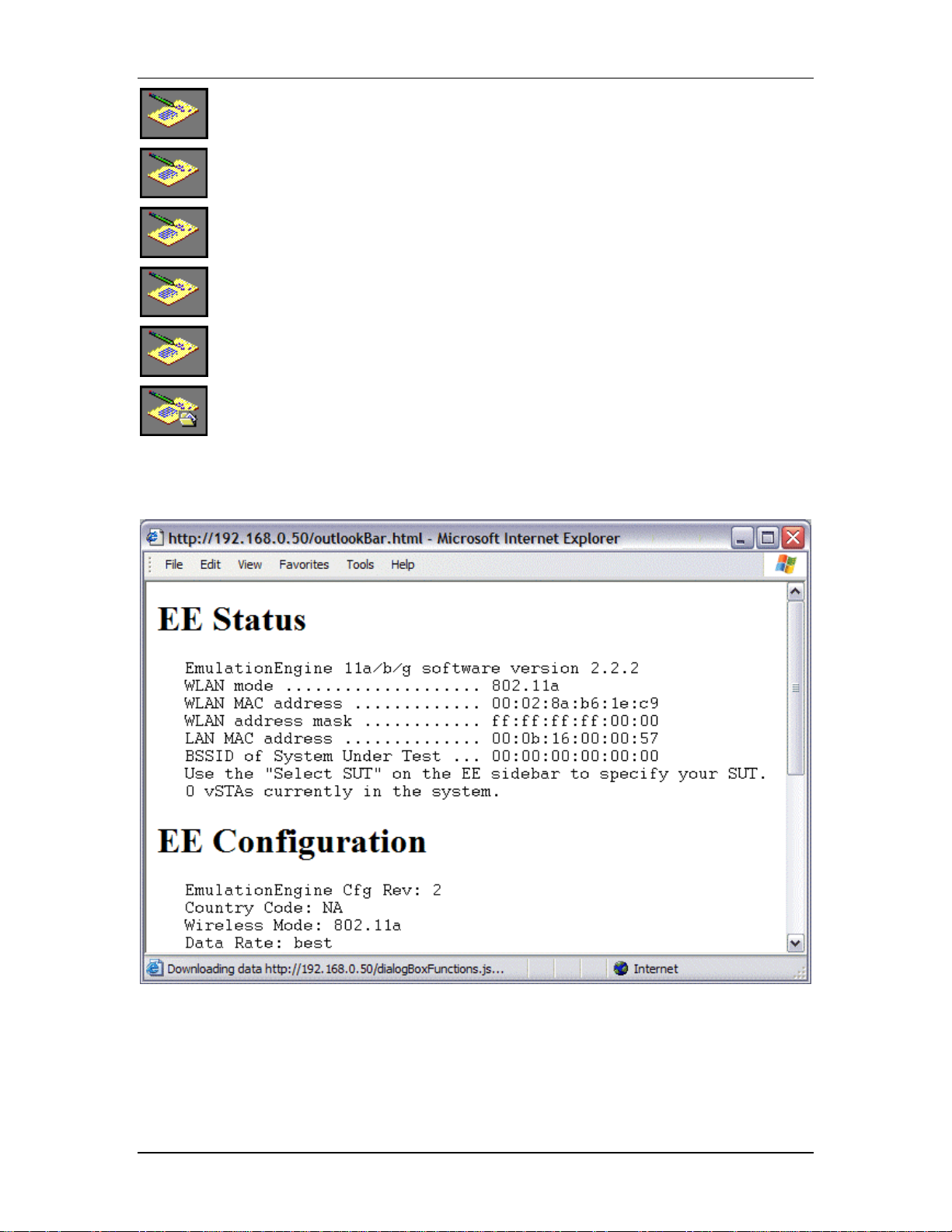
Reports->EE Configuration
The following report is displayed when t he EE Configuratio n button is
selected in the Reports side bar.
This report shows the status and configuration of the EmulationEngine.
Reports->Scenario Summary
The following statistics report is displayed when the Scenario Summary
button is selected in the Reports side bar.
5-54 080104

EmulationEngine 11a/b/g User's Guide
Summary statistics provide a summary report taken over a set of virtual
stations. The virtual station set can be a defined gro up or all virtual
stations currently in the system. In contrast, the individual virtual station
statistics report provides a list of statistics and counters for all virtual
stations. The summary report provides a summary of the statistics and
counters taken over the indicated set of virtual stations. The summary
gives, for each counter, the minimum and maximum values for that
counter found in the set of virtual stations examined, the average value,
and where applicable the total (sum) over the set of virtual stations. The
Avg fields (i.e., Receive Rate Avg, Transmit Rate (Short Frame) Avg, and
Transmit Rate (Long Frame) Avg) in the Data Rate sec tion of the
summary statistics display is the average rate for the master vSTA since
the time the EmulationEngine joined to a System Under Test. See
"Chapter 8, Statistics Counters" for a description of statistics counters that
may be displayed in this report.
Reports->Group Summary
The following statistics report is displayed when the Group Summary
button is selected in the Reports side bar.
080104 5-55

Communication Machinery Corporation (CMC)
See "Chapter 8, Statistics Counters" for a description of statistics counters
that may be displayed in this report.
Reports->vSTA Master
The following statistics report is displayed when the vSTA Master button is
selected in the Reports side bar.
See "Chapter 8, Statistics Counters" for a description of statistics counters
that may be displayed in this report.
5-56 080104

Reports->vSTA Detail
The following statistics report is displayed when the vSTA Detail button is
selected in the Reports side bar.
EmulationEngine 11a/b/g User's Guide
See "Chapter 8, Statistics Counters" for a description of statistics counters
that may be displayed in this report.
Reports->Export Reports
When the Export Reports button is selected in the Repor t s side bar, the
Generate Report dialog is displayed:
Report Details: Select one or more reports to export in the Report
Details list box.
Report Templates: Defines the directory/path where XML transf orm files
are retrieved. These XSLT files are then used to create reports from the
080104 5-57

Communication Machinery Corporation (CMC)
XML data returned by the EmulationEngine. By spec ifying another
directory path, you can customize reports to suit your needs.
!"
Select “Export” to export the report(s) to a comma-se parated values
(.CSV) file.
!"
Selec t “View” to display the selected report(s).
!"
Selec t “Cancel” to exit this dialog.
Configuration Side Bar
The buttons in the Configuration side bar are used to define encryption
keys, default ping settings, and the appearance of the web-based user
interface.
Encryption: Select this button to define Encryption keys.
Ping Defaults: Select this button to define a default ping target, ping
packet length, and number of iteration values.
Preferences: Select this button to configure the appearance of the us er
interface.
Configuration->Encryption
When the Encryption button is selected in the Configuration side bar, the
Encryption Configuration dialog is displayed:
This screen is used to define up to four shared keys for Wired Equivalency
Privacy (WEP) encryption. WEP encrypts data using an RC4 stream cipher
(from RSA Security) with a seed of 64, 128 or 152 bits before
5-58 080104

transmission to the wireless network. If you change any of the fields in
this dialog, you must select Reboot from the EE sidebar in order fo r the
new encryption selections to be recognized and used by the
EmulationEngine.
Default Authentication: Select Open System or Shared Key from the list
box.
First/Second/Third/Fourth Key: Each shared key can be 64, 128, or
152 bits. If 64 is selected in the list box, you must enter 10 hex digits. If
128 is selected in the list box, you must enter 26 hex digits. If 152 is
selected in t he list box, you must enter 32 hex digits. These keys will be
displayed in the Encryption section of the New Emulation Group dialog,
the Edit Emulation Group dialog, and the Add vSTA to Group dialog.
default: Select one of these radio buttons to identify which of the keys
should be used as the default.
NOTE: To delete a key, remove the key from the field.
!"
Click “OK” to save the Encryption keys to the EmulationEngine.
!"
Click “Cancel” to close this dialog without saving this Encryption
configuration.
Configuration->Ping Defaults
EmulationEngine 11a/b/g User's Guide
When the Ping Defaults button is selected in the Configuration side bar,
the Ping Configuration dialog is displayed. Any changes made in this
dialog w ill affect all future group/virtual station creation defaults for t his
session.
Target IP: Enter the target IP address where ICMP Echo (Ping)
Request/Response messages should be sent.
Data Length: Specify the size (64...1024) of each message.
Count: Specify the total number of pings to be sent: 0.. .10000 (0=None).
!"
Click “OK” to save the default Ping configuration.
080104 5-59

Communication Machinery Corporation (CMC)
!"
Click “Cance l” to close this dialog without saving this configur ation.
Configuration->Preferences
When the Preferences button is selected in the Configuration side bar, the
UI Configur ation dialog is displaye d.
Display vSTA Transitional States: This checkbox enables/disables
update of the web-based use r interface to show changes in virtual station
transitional states such as authenticating, associating, de-authenticating
and disassociating. Dese lecting this option will imp rove user interface
performance.
Update vSTA Stats Each Iteration: Select this checkbox to
enable/disab le auto matic up date of virtual station statistics. Stat istics are
gathered by making extra calls to the EmulationEngine. Under high virtual
station load, deselecting this op tion will improve user interface
performance.
Group/vSTA Highlight Color: Select the Color button to show a color
selector dialog and choose a color to highlight groups and virtual stations
in the group grid. After a color has been chosen, the Re set button can be
used to reset the color to its original state.
Group/vSTA Selected Color: Select the Color button to show a color
selector dialog and choose a color for selected groups and virtual stations
in the group grid. After a color has been chosen, the Re set button can be
used to reset the color to its original state.
Show Welcome Screen on Startup: Select this checkbox to
enable/disable the welcome screen that is shown when you successfully
log in to the web-based user interface .
!"
Select “OK” to close this page and save the configuration.
!"
Selec t “Cancel” to close this dialog without saving this configuration.
Menus & Toolbars
The menus and toolbars at the top of the web-based user interface can be
used to run tests, manipulate virtual stations , show results, and configure
the EmulationEngine as well as general scenario management.
5-60 080104

File Toolbar
The buttons in this toolbar are used to c reate, open, save and print
scenarios.
Edit Toolbar
The buttons in this toolbar are used to delete, cut, copy and paste virtual
stations within and between groups. It can also be used to delete groups
when a group is selected in the group control tab/table.
EmulationEngine 11a/b/g User's Guide
New Scenario: Create a new scenario
Open Scenario: Open an existing scenario
Save Scenario: Save the current scenario
Print: Print the scenario configuration
Delete: Delete cu rrently selected group(s) or virtual station(s)
Cut: Cut the currently selected virtual station(s) and place into an
intern al virtual station buffer.
Copy: Copy the selecte d virtual station(s) in to an int ernal virtual
station buffer.
Paste: Paste the virtual station definition from the internal virtual
station buffer into the currently selected group
Scenario Toolbar
The buttons in this section of the toolbar can be used to r un, pause, stop,
restart, or refresh the entire scenario of all virtual stations.
Run Scenario: Run the test for a ll group s and all virtual station s in
a scenario
Pause Scenario: Pause the test for all groups and all virtual
stations in a scenario
Term inate Scenario: Stop the test for all groups and all virtual
stations in a scenario
Reset Scenario: Reset the test for all groups and all virtual stations
in a scenario
Refresh Scenario: Refresh the test for all groups and all virtual
stations in a scenario
vSTA Toolbar
The buttons in this toolbar are used to run, pause, stop, restart, or refresh
selected virtual stations or groups of virtual stations. The s elected action
will be execut ed for the group(s) and/ or virtual station(s) that are
selected/h ighlighte d in the group control grid.
080104 5-61

Communication Machinery Corporation (CMC)
Initializ e: Initialize th e currently selected groups or virtual stations
Authenticate: This selection will cause the currently selected virtual
stations or all virtual stations in a group to initiate the
authentication sequence with the System Under Test
Associate: This selection will cau se the currently selected virtual
stations or all virtual stations in a group to initiate the assoc iation
sequence with the System Under Test
Run: Run a test for selected groups or virtual stations
Pause: Pause a test for selected groups or virtual stations
Stop: Terminate a test for selected groups or virtual stations
Disassociate: This selection will cause the cu rrently selected virtua l
stations or all virtual stations in a group to initiate the
disassociation sequence with the System Under Test
De-au thenticate: This se lection will cause the currently selected
virtua l statio ns or all virtual stations in a group to initiate the deauthentication sequence with the System Under Test
Reset: Reset a test for selected groups or virtual stations
Refresh: Refresh a test for selected groups or virtual stations
Reports Toolbar
The buttons in this toolbar are used to view reports and the event log:
View Reports: This button displays the Generate Report dialog
from which you can select a report to be displayed or exported.
View Event Log: This button displays the last 400 entries in the
event log.
Monitor Toolbar
This toolbar is located in the top-right corner of the monitoring section of
the screen. The buttons in this toolbar can be used to control monitor(s).
When the Delete Monitor button is selec ted in the monitor toolbar,
a confirmation dialog is displayed.
5-62 080104

EmulationEngine 11a/b/g User's Guide
Select Yes to delete the cur rent monitor. Select No to close this
dialog.
When the Run Monitor button is selecte d from the monitor toolbar,
the currently displayed monitor will start gathering a nd displa ying
its target statistics
When the Pause Monitor button is selected from the monitor
toolbar, the currently displayed monitor will stop its target
statistics. However, statistics will still be accumulating in the
background and are exportable.
When the Clear Monitor button is selected in the monitor toolbar, a
confirmation dialog is displayed.
Selec t Yes to clear the current mon itor. This will s et all counters in
the current monitor to zero. Statistics gathered up to this point are
not cleared and are still exportable. Select No to close this dialog
without clearing the monitor.
080104 5-63

Communication Machinery Corporation (CMC)
File Menu
New Scenario...: This selection creates a new scenario in which groups
and virtual stations can be defined.
Open Scenario...: This selection shows the Open Scenario dialog where
you can choose from a list of existing scenario files on the
EmulationEngine or browse your PC for scenario files.
Save Scenario...: This selec tion will show the Save Scena rio dialog.
Save Scenario As...: This selection can be used to save a scenario as a
new instance.
New Group...: This s election will display the New Emulation Gro up dialog.
New vSTA...: This selection will display th e Add vSTA to Group dialog.
Print: Send the curre nt scenario configuration to your printer.
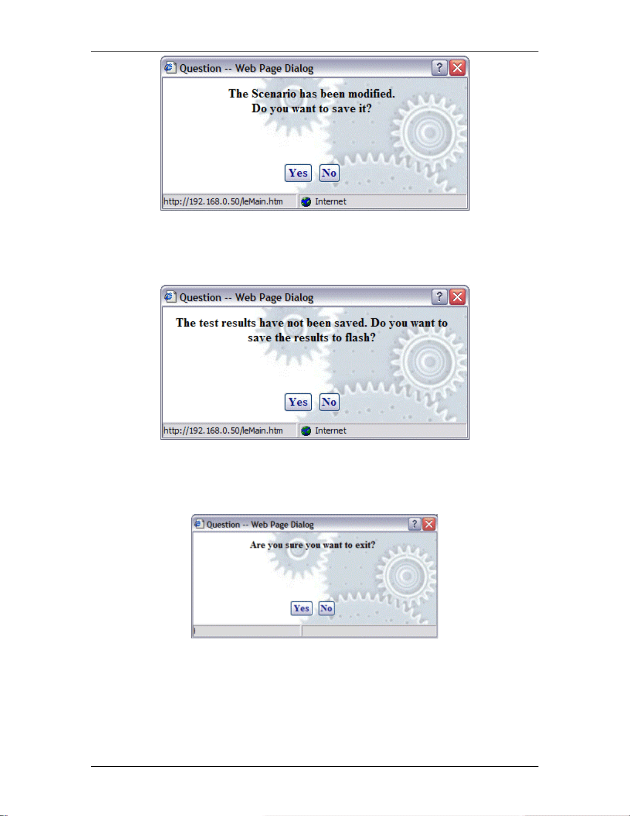
Exit Program: Exit the web-based user interface. If a scenario is
currently active/running, the following dialog is displayed:
Click Yes to continue with exit from the web-based user interface. Click No
to return to the currently running test.
If the current s cenario has been modified during this web-based us er
interface session, the following dialo g will prompt you to save these
changes.
5-64 080104
EmulationEngine 11a/b/g User's Guide
Click Yes to display the Save Scenario dialog and save the scenario on
your PC or in flash on the EmulationEngine. Click No if you do not want to
save the modified scenario.
If active virtual s tations have been configu red, a dialog will prompt you to
save the results to flash:
Click Yes to save the results of any active scenario(s) in the
EmulationEngine's flash file system. Click No to discard current test
results.
A dialog will prompt you to confirm exit from the web-based user
interface:
Click Yes to exit. Click No to return to the web-based user interf ace.
080104 5-65

Communication Machinery Corporation (CMC)
Edit Menu
Select All: If a g roup tab is selected, select all virtual stations in a
scenario group. If the Group Control tab is displayed, select all groups.
Unselect All: If a group t ab is selected, uns elect all virtual stations in a
scenario group. If the Group Control tab is displayed, unselect all groups.
Cut: Remove the definition of the currently selected virtual station and
put it in the Windows clipboard.
Copy: Copy a virtual station definition to the Windows clipboard.
Paste: Paste the virtual station definition in the Windows clipboard to the
currently selected group.
Delete: If a group tab is selected, delete the currently selecte d virtual
station. If the Group Control tab is displayed, delete the currently selected
group.
Scenario Menu
After you have def ined a scenario, use the Scenario Menu to initialize and
exercise the scenario.
Initialize: Initialize all virtual stations defined in the s cenario.
Authenticate: When this option is selected, all virtual stations defined in
a sce nario will initiate the aut hentication sequence to the System Under
Test.
Associate: When this option is selected, all virtual stations defined in a
scenario will in itiate the association seq uence to the System Under Test.
Run: Start execution of the te st defined by this scenario.
Pause: Pause the test a nd temporarily halt all virtual stations defined in
the scenario. Virtual stations may be restarted by selecting the Run
option. This option will be grayed- out (not selectable) if the scen ario is not
running.
5-66 080104

Terminate: Stop a test and halt all virtual stations defined in the
scenario. Virtual stations must be reset before they can be run again. This
option will be graye d-out (not selectable) if the scenar io is not running.
Reset: Reset all virtual stations in the scenario to an initialized state .
Statistics for the virtual stations are reset to zero. This option can be us ed
to restart any virtual stations that may have encountered problems during
a test.
Group Menu
After you have defined a group in a scenario, use the options in the Group
menu to edit and control any/all selected group(s).
EmulationEngine 11a/b/g User's Guide
Edit Group: This selection will display the Edit Emulation Group dialog.
Renumber: After new virtual stations have been cut, copied, and/or
pasted into a group , virtu al station numbering within the group will
beco me out of order (see the Edit Menu). This selection will renumbe r all
virtual stations in the group starting at one.
Initialize: Initialize all virtual stations defined in the c urrently se lected
group.
Authenticate: When this option is selected, all virtual stations in the
currently select ed group will initiate the authentication seq uence to the
System Under Test.
Associate: When this option is selected, all virtual stations in the
currently select ed group will initiate the association sequence to the
System Under Test.
Run: Start execution of all virtual stations defined in the currently
selected group(s).
Pause: Pause execution of all virtual stations defined in the currently
selected group(s). This optio n will be grayed-out (not selectable) if the
group is not running a test.
Terminate: Stop all virtual stations def ined in the currently selected
group(s). This option will be grayed-out (not selectable) if the group is not
running a test.
Reset: Reset all virtual stations defined in the currently selected group(s).
080104 5-67
Communication Machinery Corporation (CMC)
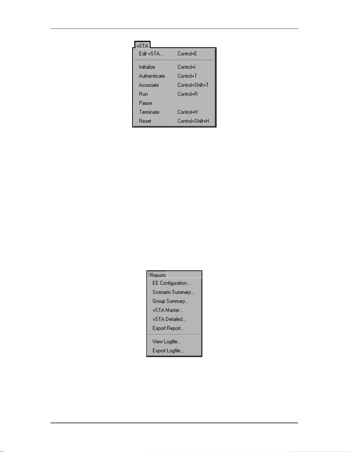
vSTA Menu
Edit vSTA...: This selection will displa y the v irtual station configuration
dialog.
Initialize: Initialize the curre ntly selected virtual station(s).
Authenticate: When this option is selected, the cu rrently selected virtua l
station(s) will initiate the authentication sequence to t he System Under
Test.
Associate: When this option is selected, the currently selected virtual
station(s) will initiate the associat ion sequence to the System Under Test.
Run: Start execution of the currently selected virtual sta tion(s).
Pause: Pause the execution of the currently selected virtual station(s).
This option will b e grayed-o ut (not selectable) if the v irtual s tation is not
running a test.
Terminate: Stop th e currently selected virtual station(s). Th is option will
be grayed-out (not se lectable) if the virtual station is not running a test.
Reset: Reset the currently selected virtual station(s).
Reports Menu
EE Configuration...: Display the EmulationEngine configuration report.
Scenario Summary...: Display the scenario summary statistics report.
Group Summary...: Display the group summary statistics report.
vSTA Master...: Display the virtual station master (i.e., EmulationEngine)
statistics report.
vSTA Detailed...: Display the virtual station detailed statistics report.
5-68 080104

Export Report...: Display the Generate Report dialog.
View Logfile...: Display event log.
Export Logfile: Display the Export Logfile dialog.
Options Menu
Configure EE...: Display the Configure Emulator dialog.
Configure Monitors...: Display the Configure Monitoring dialog.
Configure Ping...: Display the Configure Ping dialog.
EmulationEngine 11a/b/g User's Guide
Configure Encryption...: Display the Configure Encryption dialog.
Configure Event Log...: Display the Configure Event Log dialog.
Configure UI...: Display the UI (User Interface) C onfiguration dialog.
Configure Table View...: Display the Table Configuration dialog for
group tab columns.
080104 5-69

Communication Machinery Corporation (CMC)
5-70 080104
 Loading...