


FaceSentry 3 series / 5 Series
Appliance Installation Manual
FaceSentry
Appliance Installation Manual
For more information and updated manual, please visit our web site at
http://www.iwt.com.hk
1 | P a g e

FaceSentry 3 series / 5 Series
No.
Items
Quantity
Drawings
1
Controller
1
2
Panel
1
3 Series
5 Series
3
Transformer (Panel Use)
1
4
Power connection Cable - a
(Panel)
1
5
Power Connection Cable - b
(Controller)
1
6
Data Cable
1
7
Mifare Card
10
8
Key
2
Appliance Installation Manual
Content List
__________________________________________________________________________________________________________________________________________________________________________________________________________
2 | P a g e

FaceSentry 3 series / 5 Series
9
Base for Flush mount
(Optional)
1
10
Base for Wall mount
(Optional)
1
11
Screw (M3x30)
2
12
Strain Relief Bushing
1
Appliance Installation Manual
3 | P a g e

FaceSentry 3 series / 5 Series
The lightning flash with arrowhead symbol, within an equilateral triangle, is intended to alert the user to the
presence of uninsulated “dangerous voltage” within the products enclosure that may be of a sufficient magnitude
to constitute a risk of electrical shock to persons.
The exclamation mark within an equilateral triangle is intended to alert the user to the presence of important
operating and maintenance (servicing) instructions in the literature accompanying the appliance.
1. Read Instructions
All the Safety and Operating Instructions should be read before the appliance is operated.
2. Retain Instructions
The Safety and Operating Instructions should be retained for future reference.
3. Heed Warnings
All warnings on the appliance and in the Operating Instructions should be adhered to.
4. Follow Instructions
All Operating and Use Instructions should be followed. Only use attachments/accessories specified by the
manufacturer.
5. Important
Do not defeat the safety purpose of the polarized or grounding type plug. The third prong is provided for your
safety. If the provided plug does not fit into your outlet, consult an electrician for replacement of the obsolete
outlet. Refer all servicing to a qualified service personnel. Servicing is required for any damaged parts such as
power-supply cord or plug.
6. Water and Moisture
The appliance should not be used in or near water
7. Ventilation
The appliance should be situated so that its location or position does not interfere with its proper ventilation.
For example, the appliance should not be situated on a bed, sofa, or similar surface that may block any
ventilation openings.
8. Heat
The appliance should be situated away from heat sources such as radiators, heat registers, stoves or other
appliances (including amplifiers) that produce heat.
9. Power Sources
The appliance should be connected to a power supply only of the type described in the Operating Instructions
or as marked on the appliance and it shall remain readily operable. Mains plug is used as the disconnect
device. To be completely disconnected from the power input, the mains plug of the appliance must be
disconnected from the mains completely.
10. Power-cord Protection
Power supply cords should be routed so that they are not likely to be walked on or pinched by items placed
upon or against them, paying particular attention to cords at plugs, convenience receptacles and the point
where they exit from the appliance. The main plug should not be obstructed OR should be easily accessed
during intended use.
11. Attachments and
Accessories
Use only attachments/accessories specified by the manufacturer.
12. Handling
The appliance should be transported with the cart, stand, tripod, bracket, or table specified by manufacturer, or
sold with the apparatus.
When a cart is used, use caution when moving the cart/appliance combination to avoid injury from tip-over.
13. Non-use Periods
Unplug this appliance during lightning storms or when unused for long periods of time.
14. Damage Requiring
Service
The appliance should be serviced by qualified service personnel when:
a. The power supply cord or the plug has been damaged; or b. Objects have fallen or liquid has been spilled
into the appliance; or c. The appliance has been exposed to rain; or d. The appliance does not appear to
operate normally or exhibits a marked change in performance; or e. The appliance has been dropped or the
enclosure damaged.
15. Servicing
The user shall not attempt to service the appliance beyond that described in the Operating Instructions. All
other servicing should be referred to qualified service personnel.
WARNING
TO REDUCE THE RISK OF FIRE OR ELECTRICAL SHOCK, DO NOT EXPOSE THIS APPLIANCE TO RAIN OR MOISTURE
• Apparatus shall not be exposed to dripping or splashing
and no objects filled with liquids, such as vases, shall be
• The Mains plug is used as a disconnect device and shall
• This apparatus shall always be connected to an AC outlet
• To disconnect the apparatus from the mains, the plug
must be pulled out from the mains socket; therefore the
mains plug shall be readily operable.
Appliance Installation Manual
Important safety instructions
Explanation of Graphical Symbols
placed on the apparatus.
stay readily operable at any time.
with a protective grounding connection.
4 | P a g e

FaceSentry 3 series / 5 Series
1
Lock
2
Holes for wiring
3
Power Cable Terminals
4
Network Terminals
5
Data cable Terminals
6
Controller Composition
7
Screw Hole (4)
8
Relay Terminals
9
Router (For Dual Panel
Controller only)
10
Ground Connector
○
1
○
○
○
Top, Front & Bottom View
○
○
○
10
○
○
○
Appliance Installation Manual
Views
Controller
Outer:
2
Inner:
6
4
5
7
8
9
3
5 | P a g e

FaceSentry 3 series / 5 Series
1
Camera (2)
2
Monitor
3
Card Reader
4
Screw hole
5
Anti-theft alarm
6
Holes for mounting
7
Power Plug
Terminals
8
Weigand Input
9
Weigand Output
10
Data Cable Terminals
11 12
○
○
3
○
○
2
○
○
7
○
○
○
10
Top, Front & Bottom Views
Side & Back Views
○
Appliance Installation Manual
Views
Panel
5
1
6
4
9
8
6 | P a g e
FaceSentry 3 series / 5 Series
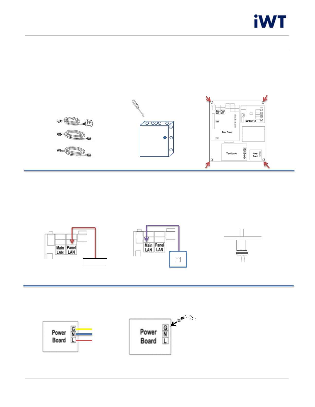
Appliance Installation Manual
Controller Installation Procedure
(1) Single Panel
1. Prepare the “Data Cable”,
RJ45 network cable
(Customer provide) and
Power Connection Cable -
b.
4. Connect Data Cable
from panel side (Data
terminals) to Controller
side (Panel LAN) and
passes through the hole
which opened on step 2.
7. Connect “Power
Connection cable - b “to
Power Board.
2. Holed the controller
according to situation
needs.
5. Connect RJ45
network cable from
controller network
terminals (Main LAN
side) to network
socket.
8. Connect ground cable
from power board (G)
to Ground Connector.
3. Secure the controller by
screws.
6. Secure the “Power
Connection cable - b
“by “Strain Relief
Bushing”.
7 | P a g e

FaceSentry 3 series / 5 Series
Panel A
Panel B
Appliance Installation Manual
Controller Installation Procedure
(2) Dual Panel
1. Prepare the “Data Cable”
x 2, RJ45 network cable
(Customer provide) and
“Power Connection Cable
– b”.
4. Connect Data Cable from
panel side (Data terminals)
to Controller side (Router
terminals either 2-5) and
passes through the hole
which opened on step 2.
2. Holed the controller
according to situation
needs.
5. Repeat Step 4 on Panel B.
3. Secure the controller by
screws.
6. Connect RJ45 network
cable from controller
network terminals (Main
LAN side) to network
socket.
7. Secure the “Power
Connection cable - b “by
“Strain Relief Bushing”
8. Connect “Power
Connection cable - b “to
Power Board.
9. Connect ground cable
from Power Board (G)
to Ground Connector.
8 | P a g e

FaceSentry 3 series / 5 Series
.
.
.
.
.
.
Wall
.
.
Appliance Installation Manual
Panel Installation Procedure
FaceSentry mounts on wall by: (A) Flush mounting, (B) Wall mounting
(A) Flush mounting (Please install with “Base for flush mounting”)
1. Reserve a suitable
position for flush
mounting, the panel
mounting suggests 132
cm apart from ground.
4. Reserve a hole on base
for wiring.
7. Screw the panel on the
wall
2. Dig enough space to
fit the Base (practical
dimension on Page14)
5. Mount the base on wall
by screw.
8. Finish Panel
installation.
3. Drill the holes for
base mounting.
6. Connect Data Cable
and Panel power
supply cable to panel.
9 | P a g e

FaceSentry 3 series / 5 Series
Wall
Panel Power
Supply*
Data Cable
Power Supply Plug
Appliance Installation Manual
Panel Installation Procedure
(B) Wall mounting (Please install with “Base for Wall mounting”)
1. Reserve a suitable position
for flush mounting, the
panel mounting suggests
132 cm apart from ground.
4. Connect Data Cable and
Panel power supply cable
to panel.
2. Drill the holes for
base mounting.
5. Screw the panel on
the wall
3. Secure the base on the
wall by screw.
6. Finish Panel installation.
10 | P a g e

FaceSentry 3 series / 5 Series
Parameter
Min
Typical
Max
Unit
Remark
DC Main Power Supply Voltage
11.5
12
12.4
V
(*1)
DC Main Power Supply Current(*2)
0.2 2 3 A
DC Main Power Supply Current(*3)
0.2
0.5 1 A
RTC Backup Battery Voltage
1.8
3.2
3.3 V
Storage Temperature
-20 / 60
°C
Operation Temperature
-10
25
50
°C
Parameter
Conditions
Input Voltage
100-120V, AC 2.8A
220-240V, AC 1.6A
Frequency Range
50/60Hz
Overload
110 ~ 150% rated output power
Protection type : Hiccup mode, recovers automatically after fault
condition is removed
Over Voltage
CH1: 5.75 ~ 6.75V
Protection type : Hiccup mode, recovers automatically after fault
condition is removed
Operation Temperature
0 ~ 60°C (32 ~ 140°F)
Storage Temperature
-40 ~ 75°C (-40 ~ 167°F)
Operating Humidity
0% ~ 90% Relative Humidity, Non-condensing
Appliance Installation Manual
Recommended Operating Conditions
Controller
Panel
(*1) Onboard over-voltage protection scheme protects fill light, Wiegand power output against high-
voltage faults. The lockout threshold varies from 12.4V to 12.8V as the temperature varies.
(*2) In situation that with fill light and Wiegand card reader.
(*3) In situation that without fill light and Wiegand card reader.
11 | P a g e

FaceSentry 3 series / 5 Series
Problems
Checklists
Solution
No operation after power on
(Panel or Controller)
properly inserted to main
supply?
terminals?
- Fully put the power plug to
the terminals
- Checked above but no
operation and no power
light.
- Send back to your supplier
for repair
No time message display after
start-up
- The Data cable is properly
inserted on controller and
panel?
- The controller already start up?
- Unplug and plug the power
supply from panel.
No operation on camera
- Swipe user card, any photo
captured on access log?
- Unplug and plug the power
supply from panel.
Appliance Installation Manual
Malfunction / Maintenance
12 | P a g e

FaceSentry 3 series / 5 Series
3 Series
5 Series
32.5 cm
65 cm
7 cm
40.2 cm
2.9 cm
38.8 cm
2.9 cm
11.7 cm
36.6 cm
36.6 cm
Appliance Installation Manual
Dimensions A
Controller:
Panel:
13 | P a g e
FaceSentry 3 series / 5 Series
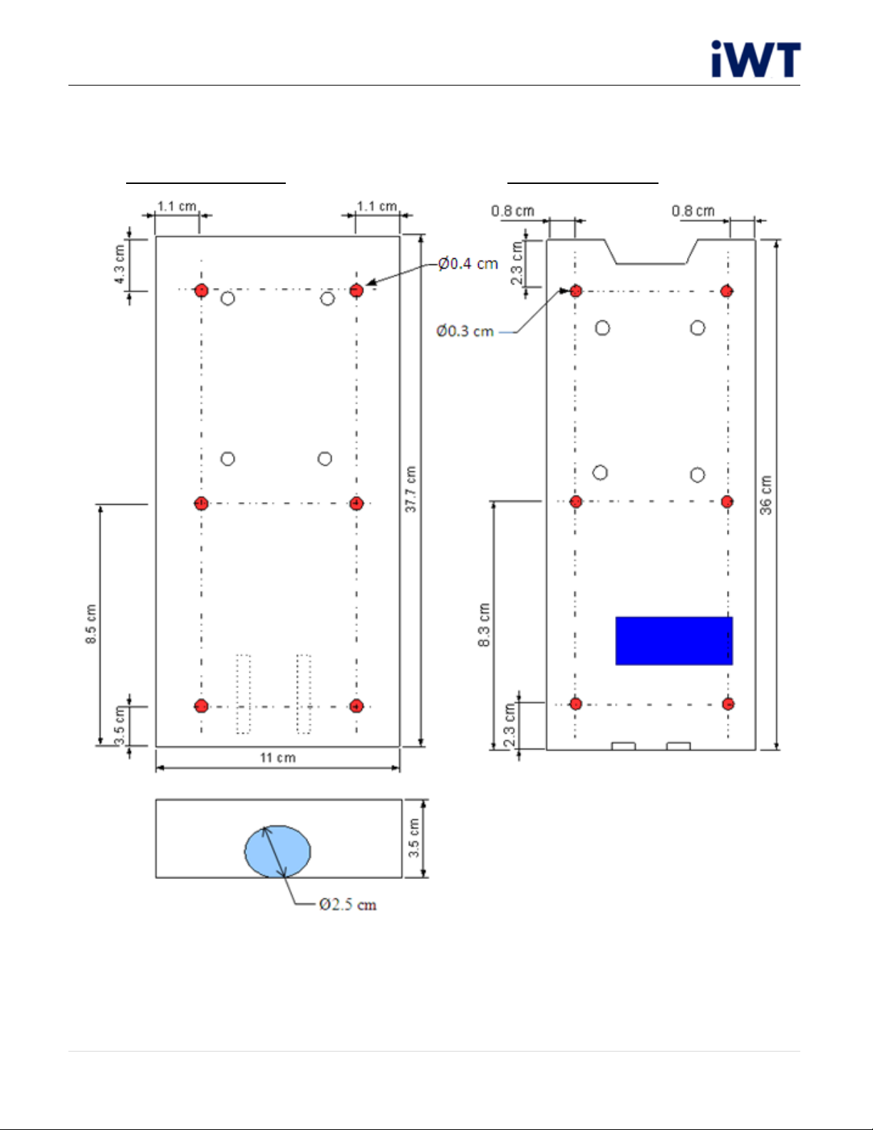
Appliance Installation Manual
Dimensions B
Base for Flush Mount Base for Wall mount
14 | P a g e

FCC Warning:
z This device complies with Part 15 of the FCC Rules. Operation is subject to the
following two conditions:
z (1) this device may not cause harmful interference, and
z (2) this device must accept any interference received, including interference that
may cause undesired operation.
z Changes or modifications not expressly approved by the party responsible for
compliance could void the user's authority to operate the equipment.
z NOTE: This equipment has been tested and found to comply with the limits for a
Class B digital device, pursuant to Part 15 of the FCC Rules. These limits are
designed to provide reasonable protection against harmful interference in a
residential installation. This equipment generates, uses and can radiate radio
frequency energy and, if not installed and used in accordance with the
instructions, may cause harmful interference to radio communications. However,
there is no guarantee that interference will not occur in a particular installation. If
this equipment does cause harmful interference to radio or television reception,
which can be determined by turning the equipment off and on, the user is
encouraged to try to correct the interference by one or more of the following
measures:
z -- Reorient or relocate the receiving antenna.
z -- Increase the separation between the equipment and receiver.
z -- Connect the equipment into an outlet on a circuit different from that to which
the receiver is connected.
z -- Consult the dealer or an experienced radio/TV technician for help.
 Loading...