

Page 1

Installation Guide
LCI2 User Interface Module
502-002
SUPERSEDES: October 22, 2010
Plant ID: 001-3949
Table of Contents
LCI2 . . . . . . . . . . . . . . . . . . . . . . . . . . . . . . . . . . . . . . . 2
Overview. . . . . . . . . . . . . . . . . . . . . . . . . . . . . . . . . . . . 2
Features. . . . . . . . . . . . . . . . . . . . . . . . . . . . . . . . . . 2
Applicable Documentation . . . . . . . . . . . . . . . . . . . .3
Typical Use . . . . . . . . . . . . . . . . . . . . . . . . . . . . . . .3
Representations and Warranties . . . . . . . . . . . . . . . . . 3
Precautions. . . . . . . . . . . . . . . . . . . . . . . . . . . . . . . . . . 4
General . . . . . . . . . . . . . . . . . . . . . . . . . . . . . . . . . .4
Static Electricity . . . . . . . . . . . . . . . . . . . . . . . . . . . . 4
Location . . . . . . . . . . . . . . . . . . . . . . . . . . . . . . . . . . 4
FCC Compliance . . . . . . . . . . . . . . . . . . . . . . . . . . . 4
Before Installing . . . . . . . . . . . . . . . . . . . . . . . . . . . . . . 5
About this Document . . . . . . . . . . . . . . . . . . . . . . . . 5
Inspecting the Equipment . . . . . . . . . . . . . . . . . . . . 5
What is Not Included with this Equipment . . . . . . . . 5
Equipment Location . . . . . . . . . . . . . . . . . . . . . . . . .5
Selecting a Power Source . . . . . . . . . . . . . . . . . . . . 5
EFFECTIVE: November 12, 2010
Installation . . . . . . . . . . . . . . . . . . . . . . . . . . . . . . . . . . 5
Mounting the Device . . . . . . . . . . . . . . . . . . . . . . . . 5
Device Connections . . . . . . . . . . . . . . . . . . . . . . . . . . . 6
Ethernet (LAN). . . . . . . . . . . . . . . . . . . . . . . . . . . . . 7
Network (LON). . . . . . . . . . . . . . . . . . . . . . . . . . . . . 8
Grounding the Device . . . . . . . . . . . . . . . . . . . . . . . 8
Specifications . . . . . . . . . . . . . . . . . . . . . . . . . . . . . . . . 8
Electrical . . . . . . . . . . . . . . . . . . . . . . . . . . . . . . . . . 8
Mechanical. . . . . . . . . . . . . . . . . . . . . . . . . . . . . . . . 9
Troubleshooting Tips . . . . . . . . . . . . . . . . . . . . . . . . . . 9
© 2010 Taco Electronic Solutions, Inc. 1
Page 2

iWorX® LCI2
LCI2
The LCI2 (LCI2) is the master controller for the iWorX® product series. In one single device, it provides an integrated
control center for all the HVAC controls, radiant controls, and metering on a network. It has a touch screen for on site
configuration and can be remotely accessed and configured over the Internet as well.
OVERVIEW
The LCI2 is a backlit LCD touch screen interface and system configuration tool used to communicate with controllers
over a LONWORKS ® network. All controllers can be completely configured and commissioned through the operator
interface.
The LCI2 fully integrates the HVAC iWorX® system. The LCI2 enables an administrator to add and configure devices
on the iWorX® system and then send the information to the devices over the LONWORKS network. The entire iWorX®
system can be commissioned and modified using the LCI2 touch screen interface.
The LCI2 software runs within a Windows CE.net operating system and is fully upgradable.
Features
• Color touch screen interface for navigation and input
• Self-configuring upon connection to the network
• Configurable user interface options
• View and configure up to 63 controllers
• Administrator and user level access
• Password protection
• Ethernet communications for PC-based configuration
• User configuration data is stored in non-volatile memory (Flash)
• Two-part connectors to facilitate installation
2 502-002, Effective: November 12, 2010
© 2010 Taco Electronic Solutions, Inc.
Page 3
iWorX® LCI2
Applicable Documentation
Description Audience Purpose
iWorX® LCI2 Application Guide,
Document No. 505-002
iWorX® LCI2 Quick Start Guide,
Document No. 505-002a
http://iWorxWizard.taco-hvac.com – Application Engineers
Additional Documentation LonWorks FTT-10A Free Topology Transceiver User’s Guide, published by Echelon Corpora-
– Application Engineers
– Installers
– Service Personnel
– Start-up Technicians
– End user
– Application Engineers
– Installers
– Service Personnel
– Start-up Technicians
– End user
– Wholesalers
– Contractors
tion. It provides specifications and user instructions for the FTT-10A Free Topology Transceiver. See also: www.echelon.com/support/documentation/manuals/transceivers.
Provides complete instructions for setting up and
using the iWorX® Local Control Interface.
Provides brief, basic instructions for setting up and
using the iWorX® Local Control Interface.
An on-line configuration and submittal package generator based on user input. Automatically generates
bill of materials, sequence of operations, flow diagrams, wiring diagrams, points and specifications.
Typical Use
BZU2
DXU4
BLMC
ZXU1
REPRESENTATIONS AND WARRANTIES
This Document is subject to change from time to time at the sole discretion of Taco Electronic Solutions, Inc. All
updates to the Document are available at www.taco-hvac.com. When installing this product, it is the reader’s responsibility to ensure that the latest version of the Document is being used.
The iWorX® LCI2 shall only be used for the applications identified in the product specifications and for no other purposes. For example, the iWorX® LCI2 is not intended for use to support fire suppression systems, life support systems,
critical care applications, commercial aviation, nuclear facilities or any other applications where product failure could
lead to injury to person, loss of life, or catastrophic property damage and should not be used for such purposes.
502-002, Effective: November 12, 2010 3
© 2010 Taco Electronic Solutions, Inc.
Page 4

iWorX® LCI2
Taco Electronic Solutions, Inc. will not be responsible for any product or part not installed or operated in conformity with
the Document and instructions or which has been subject to accident, disaster, neglect, misuse, misapplication, inadequate operating environment, repair, attempted repair, modification or alteration, or other abuse. For further information, please refer to the last page of this Document for the company’s Limited Warranty Statement, which is also issued
with the product or available at www.taco-hvac.com.
PRECAUTIONS
General
This symbol is intended to alert the user to the presence of important installation and maintenance (servicing) instructions in the literature accompanying the equipment.
WARNING: Electrical shock hazard. Disconnect ALL power sources when installing or servicing this
equipment to prevent electrical shock or equipment damage.
Make all wiring connections in accordance with these instructions and in accordance with pertinent national and local
electrical codes.
Static Electricity
Static charges produce voltages that can damage this equipment. Follow these static electricity precautions when handling this equipment.
• Work in a static free area.
• Touch a known, securely grounded object to discharge any static charge you may have accumulated.
• Use a wrist strap when handling printed circuit boards. The wrist strap must be secured to earth ground.
Location
Avoid locations where corrosive fumes, excessive moisture, vibration or explosive vapors are present.
Avoid electrical noise interference. Do not install near large contactors, electrical machinery, or welding equipment.
This equipment is intended for indoor use only. Operate where ambient temperatures do not exceed 113 °F (45 °C) or
fall below 32 °F (0 °C) and relative humidity does not exceed 80%, non-condensing.
FCC Compliance
This equipment has been tested and found to comply with Part 15 of the FCC rules. These limits are designed to provide reasonable protection against harmful interference. This equipment can radiate radio frequency energy and, if not
installed and used in accordance with the instructions, may cause harmful interference to radio communications. However, there is no guarantee that interference will not occur in a particular installation. If this equipment does cause
harmful interference to radio or television reception, which can be determined by turning the equipment off and on, the
user is encouraged to try to correct the interference by one or more of the following measures:
• Reorient or relocate the receiving antenna.
• Increase the separation between the equipment and the receiver.
• Connect the equipment to a power source different from that to which the receiver is connected.
• Consult the equipment supplier or an experienced radio/TV technician for help.
You are cautioned that any changes or modifications to this equipment not expressly approved in these instructions
could void your authority to operate this equipment in the United States.
4 502-002, Effective: November 12, 2010
© 2010 Taco Electronic Solutions, Inc.
Page 5

iWorX® LCI2
BEFORE INSTALLING
About this Document
The instructions in this document are for the LCI2 module which provides interfacing and scheduling of HVAC.
Inspecting the Equipment
Inspect the shipping carton for damage. If damaged, notify the carrier immediately. Inspect the equipment for damage.
Return damaged equipment to the supplier.
What is Not Included with this Equipment
• A power source for the equipment electronics and peripheral devices.
• Tools necessary to install, troubleshoot and service the equipment.
• The screws needed to mount the device.
• Peripheral devices, such as sensors, actuators, etc.
• Cabling, cabling raceway, and fittings necessary to connect this equipment to the power source, FTT-10A network
and peripheral devices.
Equipment Location
Abide by all warnings regarding equipment location provided earlier in this document.
The equipment should be installed in a secure area like an office or lockable closet.
The LCI2 should be mounted where all operators can easily access it and should not under any circumstances be
mounted outside. The LCI2 should not be mounted where it is subjected to excessive heat, moisture, corrosive or hazardous materials. To ensure that operators of all sizes can easily access the LCI2, mounting should be approximately 4
feet (1.2 meters) from the floor. Note that product mounting may be subject to local and national persons with disabilities acts.
Selecting a Power Source
This equipment requires a UL recognized external Class 2 power source (not supplied) to operate. The LCI2 power
input requires a voltage of 28 to 36 volts DC or 24 volts AC.
INSTALLATION
Warning: Electrical shock hazard. To prevent electrical shock or equipment damage, disconnect ALL
power sources to controllers and loads before installing or servicing this equipment or modifying any wiring.
Mounting the Device
The LCI2 can be either 3-point mounted (on a wall) or 4-point mounted (on a panel).
The 3-point method uses M4, 5, 6 or No. 10 or 12 screws. A ramped keyhole slot in the top back center of the unit slips
over a screw head and as the unit is lowered the unit clamps onto the wall creating a seal around the rear aperture.
Then, the two lower fixing holes can be used to spot their fixing positions.
502-002, Effective: November 12, 2010 5
© 2010 Taco Electronic Solutions, Inc.
Page 6

iWorX® LCI2
The 4-point method uses 4 off M4 x 16 mm screws with a maximum panel thickness of 10 mm.
Figure 1: Mounting
DEVICE CONNECTIONS
The LCI2 functions as part of a LONWORKS Network using the integral FTT-10 Free Topology communications transceiver. Connections are on the bottom of the LCI2.
Power
The LCI2 requires class 2 power supply: 24 Vac, 50/60 Hz, or 28 to 36 Vdc. The maximum consumption is 13 VA. Use
a separate power source—do not use a controller’s auxiliary supply output.
NOTE You must ground the LCI2 using a supply earth terminal.
6 502-002, Effective: November 12, 2010
© 2010 Taco Electronic Solutions, Inc.
Page 7

Figure 2: Power
Class 2
Figure 3: Routing cables
iWorX® LCI2
Ethernet (LAN)
The LCI2 uses a standard RJ-45 jack for connection to 10BaseT or 100Base TX (10/100Mb) Ethernet. Plug the LAN
connector into the RJ-45 receptacle on the bottom of the LCI2.
502-002, Effective: November 12, 2010 7
© 2010 Taco Electronic Solutions, Inc.
Page 8

iWorX® LCI2
Network (LON)
The LCI2 requires twisted pair network wire. When connecting the FTT-10A network to connector, connect the twisted
pair to pins NB and NA. These positions are Network B and Network A respectively. Polarity is not an issue since an
FTT-10A network is used for communications.
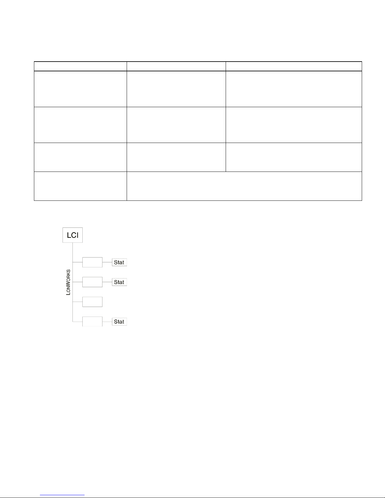
Figure 4: Simple architecture
BZU2
DXU4
BLMC
ZXU1
Grounding the Device
The COM pin must be securely connected to earth ground. Failure to properly ground this equipment may
increase the risk of electrical shock and may increase the possibility of interference to radio/TV reception.
Connecting the device common to earth ground will also connect the power source to earth ground.
SPECIFICATIONS
Electrical
Power
Power Requirements
• 28 to 36 Vdc, or 24 Vac +/- 10%, 50 to 60 Hz (requires a class 2 external supply)
Power Consumption
• 13 VA
Fusing
• Input supply is protected by a 1.6 A self-resetting electronic circuit breaker.
Battery
• 3V Lithium for SRAM Backup
Display
• 256 color LCD display (320 x 240 pixels) with touch screen and digital contrast.
Backlight
• Electroluminescent (CCFL) with auto-dimming feature. Life of 50 Khrs at 20 °C (68 °F).
Ethernet
• One RJ45 connector, unshielded or shielded twisted pair (UTP or FTP) cable.
8 502-002, Effective: November 12, 2010
© 2010 Taco Electronic Solutions, Inc.
Page 9

iWorX® LCI2
Recommended Sensor Wire
Cable Type Pairs Details Taco Catalog No.
18AWG 1 Stranded Twisted Shielded Pair, Plenum WIR-018
FTT-10A Network
• Speed: 78KBPS
• Cabling: Maximum node-to-node distance: 1312 feet (400 meters)
• Maximum total distance: 1640 feet (500 meters)
Cable Type Pairs Details Taco Catalog No.
Level 4 22AWG (0.65mm) 1 Unshielded, Plenum, U.L. Type CMP WIR-022
For detailed specifications, refer to the FTT-10A Free-Topology Transceiver User’s Guide published by Echelon Corporation (www.echelon.com/support/documentation/manuals/transceivers).
Mechanical
Housing
• Dimensions: 8.94” (227mm) x 8.58” (218mm) x 2.36” (60mm).
• Weight: 1lb 5 oz. (.6 kg)
• ABS
Environmental
• Temperature: 32 to 113 degrees F (0 to 45 degrees C)
• Humidity: 0 to 80 percent, non-condensing
Agency Listings
• UL Listed for US and Canada, Energy Management Equipment PAZX and PAZX7
Agency Compliances
• FCC Part 15
TROUBLESHOOTING TIPS
This section provides common problems and remedies for the controller.
Problem Solution
Nothing appears on the LCI2 screen
once it is powered up.
I can’t log on to the LCI2, is there a
default password?
I can’t communicate to any controllers
on the network.
This is most likely related to the input power for the LCI2, ensure the following. A blue LED should be visible on the front of the unit, indicating
that the power is on.
– Is the power source turned on?
– Is the LCI2 powered using 12-24 VDC or 24 VAC?
– Is the power connected to the correct pins?
– Is the contrast adjusted?
The LCI2 has two (2) default passwords, one for the user and one for the
administrator. The default user password is LCI2user and the default
administrator is LCI2. To reset the password, please read the Restore
LCI2 factory defaults section. Be aware that ALL custom settings such as
IP Address will also be reset.
– Ensure that the communications cable is connected to the FTT-10A
connector pins NA & NB.
– Were the service pins on the controllers depressed after the network
was configured?
– Is the FTT-10A Network Resistor Termination Configuration Jumper
set properly?
502-002, Effective: November 12, 2010 9
© 2010 Taco Electronic Solutions, Inc.
Page 10

iWorX® LCI2
Problem Solution
I am not receiving service pings at the
LCI2.
After powering down the LCI2, the
database has been cleared.
The screen seems too sensitive to my
touch or is not sensitive enough for
my touch.
– Ensure that the communications cable is connected to the FTT-10A
connector pins NA & NB.
– Were the service pins on the controllers depressed after the network
was configured?
– Is the FTT-10A Network Resistor Termination Configuration Jumper
set properly?
Check the battery voltage and ensure that it is above 2.7 VDC.
From the main menu you need to select the Utilities: LCI Setup menu
and configure the touch screen. When reconfiguring the screen you need
to apply the pressure that you would normally use when using the LCI2.
Getting Help
Components within iWorX® LCI2 controller cannot be field repaired. If there is a problem with a controller, follow the
steps below before contacting your local TES representative or TES technical service.
1.Make sure controllers are connected and communicating to desired devices.
2.Record precise hardware setup indicating the following:
Version numbers of applications software.
Controller firmware version number.
A complete description of difficulties encountered.
Notes:
10 502-002, Effective: November 12, 2010
© 2010 Taco Electronic Solutions, Inc.
Page 11

iWorX® LCI2
502-002, Effective: November 12, 2010 11
© 2010 Taco Electronic Solutions, Inc.
Page 12

iWorX® LCI2
LIMITED WARRANTY STATEMENT
Taco Electronic Solutions, Inc. (TES) will repair
or replace without charge (at the company's
option) any product or part which is proven
defective under normal use within one (1) year
from the date of start-up or one (1) year and six
(6) months from date of shipment (whichever
occurs first).
In order to obtain service under this warranty, it
is the responsibility of the purchaser to
promptly notify the local TES stocking distributor or TES in writing and promptly deliver the
subject product or part, delivery prepaid, to the
stocking distributor. For assistance on warranty returns, the purchaser may either contact
the local TES stocking distributor or TES. If the
subject product or part contains no defect as
covered in this warranty, the purchaser will be
billed for parts and labor charges in effect at
time of factory examination and repair.
Any TES product or part not installed or operated in conformity with TES instructions or
which has been subject to accident, disaster,
neglect, misuse, misapplication, inadequate
operating environment, repair, attempted
repair, modification or alteration, or other
abuse, will not be covered by this warranty.
TES products are not intended for use to support fire suppression systems, life support systems, critical care applications, commercial
aviation, nuclear facilities or any other applications where product failure could lead to injury
to person, loss of life, or catastrophic property
damage and should not be sold for such purposes.
If in doubt as to whether a particular product is
suitable for use with a TES product or part, or
for any application restrictions, consult the
applicable TES instruction sheets or in the U.S.
contact TES at 401-942-8000 and in Canada
contact Taco (Canada) Limited at 905-564-
9422.
TES reserves the right to provide replacement
products and parts which are substantially similar in design and functionally equivalent to the
defective product or part. TES reserves the
right to make changes in details of design, construction, or arrangement of materials of its
products without notification.
TES OFFERS THIS WARRANTY IN LIEU OF
ALL OTHER EXPRESS WARRANTIES. ANY
WARRANTY IMPLIED BY LAW INCLUDING
WARRANTIES OF MERCHANTABILITY OR
FITNESS IS IN EFFECT ONLY FOR THE
DURATION OF THE EXPRESS WARRANTY
SET FORTH IN THE FIRST PARAGRAPH
ABOVE.
THE ABOVE WARRANTIES ARE IN LIEU OF
ALL OTHER WARRANTIES, EXPRESS OR
STATUTORY, OR ANY OTHER WARRANTY
OBLIGATION ON THE PART OF TES.
TES WILL NOT BE LIABLE FOR ANY SPECIAL, INCIDENTAL, INDIRECT OR CONSEQUENTIAL DAMAGES RESULTING FROM
THE USE OF ITS PRODUCTS OR ANY INCIDENTAL COSTS OF REMOVING OR
REPLACING DEFECTIVE PRODUCTS.
This warranty gives the purchaser specific
rights, and the purchaser may have other rights
which vary from state to state. Some states do
not allow limitations on how long an implied
warranty lasts or on the exclusion of incidental
or consequential damages, so these limitations
or exclusions may not apply to you.
CONTROLS MADE EASY
Taco Electronic Solutions, Inc., 1160 Cranston Street, Cranston, RI 02920
Telephone: (401) 942-8000 FAX: (401) 942-2360.
Taco (Canada), Ltd., 8450 Lawson Road, Unit #3, Milton, Ontario L9T 0J8.
Telephone: 905/564-9422. FAX: 905/564-9436.
Taco Electronic Solutions, Inc. is a subsidiary of Taco, Inc.
Visit our web site at: http://www.taco-hvac.com
Printed in the USA iWorX® and iView® are registered trademarks of Taco Electronic Solutions, Inc.
© 2010 Taco Electronic Solutions, Inc. LON, LONWORKS, & LONMARK are trademarks of Echelon Corporation
®
 Loading...