

Page 1

GA-200 Gas Analyzer
Technical
Note
GA-200 Gas Analyzer
Overview
The GA-200 Gas Analyzer uses sensors to measure and display the
concentrations of oxygen and carbon dioxide in a sample as the percentage of a
gas in the sample by volume. This method of expressing the concentration of a gas
in a sample is also known as the percent volume fraction. In addition to the
sampling and sensing systems in the GA-200, the unit has a fluorescent display
used for observing measurements and analog outputs that allow the unit to be
connected to iWorx data recorders.
When measuring the concentrations of oxygen and carbon dioxide in a gas, a
sample is pumped from the input port on the front panel of the GA-200, through the
sample cell, and out an exhaust port on the back of the unit. Gas samples are
drawn into the unit through an external filter on the input port that protects the
sensors from contamination and through Nafion tubing connected to the filter that
removes moisture from the samples that would affect the measurements and the
unit's calibration.
The GA-200 Gas Analyzer has the ability to measure and record both oxygen and
carbon dioxide concentrations over the ranges normally recorded from human and
animal subjects.
Front Panel
iWorx Systems, Inc.
www.iworx.com
LabScribe is a trademark of
iWorx Systems, Inc.
©2015 iWorx Systems, Inc.
GA-200 Front Panel
Page 2
GA-200 Gas Analyzer
The front panel of the GA-200 (both A and B) has a keypad, a display used to
program the modes and parameters of the unit, and an inlet port for the gas
sample. For use with LabScribe and iWorx data recorders, it is not necessary to do
any programming through the keypad. All parameters are set in the software, as
described below.
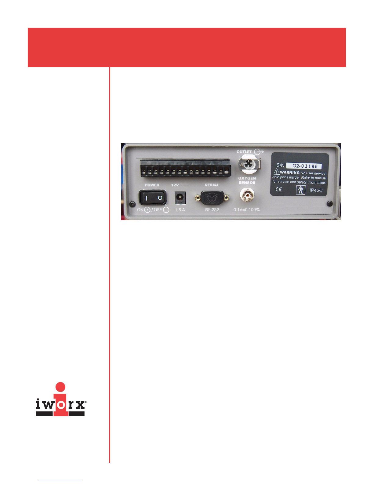
Rear Panel: GA-200A
GA-200A Rear Panel
iWorx Systems, Inc.
www.iworx.com
The rear panel of the GA-200A has the following features: a switch, a power input,
an RS-232 serial port for connection to a computer, an oxygen sensor output, and
a gas outlet. The output of the carbon dioxide sensor is incorporated into the relay
terminal which allows the unit to be connected to other devices.
1) Power for the GA-200A is supplied by an external power supply. The power
supply is connected to the unit through the connector labeled 12V, 1.5A. Press
the side of the power switch labeled I to turn on the GA-200A. Press O on the
switch when it is time to turn the unit off.
2) The GA-200A can be interfaced to a computer through a serial (RS-232) data
stream. The default data format is 9600 baud, 8 bit, and no parity with
alternate baud rates of 2400, 4800, 19200, and 38400. The signals present are
RXD, TXD, and ground through the 9-pin D connector on the back panel of the
unit.
3) The signal from the oxygen sensor can be recorded from the BNC output
labeled OXYGEN SENSOR, 0-1V = 0-100%. The amplitude of the signal
ranges from 0 to 1 Volt DC which corresponds to a range of 0 to 100% oxygen,
or 1mV for each 0.01% oxygen. The ground of this output is common to the
instrument case and the power supply.
4) The exhaust port of the sampling circuit is labeled OUTLET. A scavenging
system can be connected to this port to collect any gases passing through the
GA-200A.
5) Several relays are available from the terminal block on the rear panel of the
GA-200A. These relays are normally open, but close when the oxygen sensor
detects various alarm conditions. For DC loads, these relays are rated from 5
Amps at 30 Volts DC to 0.25 Amps at 300 Volts DC in an open circuit. For AC
loads, these relays are rated from 5 Amps at 250 Volts. When the sockets are
Page 3
GA-200 Gas Analyzer
numbered from left to right:
• Sockets 1 (Common), 2 (NC), and 3 (NO) are the connections for Limit
Relay A.
• Sockets 4 (Common), 5 (NC), and 6 (NO) are for Limit Relay B.
• Sockets 7 (Common), 8 (NC), and 9 (NO) are for Warning Relay.
• Sockets 10 (Common), 11 (NC), and 12 (NO) are for System OK.
6) An analog output for the carbon dioxide sensor and an additional analog output
for the oxygen sensor are available from the terminal block. These outputs are
non-isolated current sources that are referenced to the current output ground.
The range of each current output is 4 to 20 mA and a maximum output voltage
of 10 Volts. The oxygen and carbon dioxide concentrations that are equal to the
outputs at 4 mA and 20 mA are normally set to the low and high limits of the
sensitivity ranges of the two gases, respectively: For example, the 4 mA current
output of the oxygen sensor is set to 0%, and the 20 mA current output is set to
100%.
• Socket 13 is the Ground for the both current outputs.
• Socket 14 is the oxygen current output.
• Socket 15 is the carbon dioxide current output.
iWorx Systems, Inc.
www.iworx.com
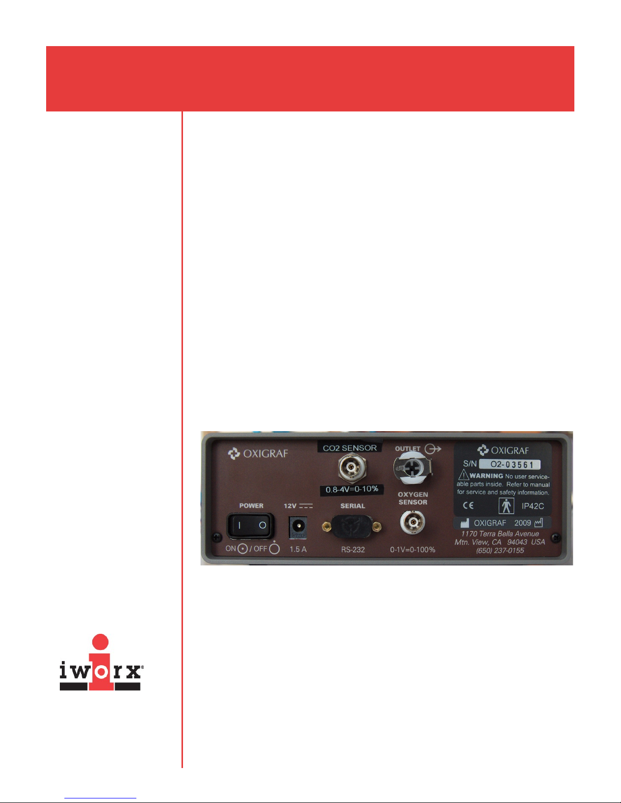
GA-200B: Rear Panel
GA-200B Rear Panel
The rear panel of the GA-200B has the following features: a switch, a power input,
an RS-232 serial port for direct connection to a computer, an oxygen sensor
output, a carbon dioxide sensor output, and a gas outlet.
1) Power for the GA-200B is supplied by an external power supply. The power
supply is connected to the unit through the connector labeled 12V, 1.5A. Press
the side of the power switch labeled I to turn on the GA-200B. Press O on the
switch when it is time to turn the unit off.
2) The GA-200B can be interfaced to a computer through a serial (RS-232) data
stream. The default data format is 9600 baud, 8 bit, and no parity with
alternate baud rates of 2400, 4800, 19200, and 38400. The signals present are
RXD, TXD, and ground through the 9-pin D connector on the back panel of the
unit.
Page 4

GA-200 Gas Analyzer
3) The signal from the oxygen sensor can be recorded from the BNC output
labeled OXYGEN SENSOR, 0-1V=0-100%. The amplitude of the signal ranges
from 0 to 1 Volt DC which corresponds to a range of 0 to 100% oxygen, or 1mV
for each 0.01% oxygen. The ground of this output is common to the instrument
case and the power supply.
4) The signal from the carbon dioxide sensor can be recorded from the BNC
output labeled CO2 SENSOR, 0.8-4V=0- 10%. The amplitude of the signal
ranges from 0.8 to 4 Volt DC which corresponds to a range of 0 to 10% carbon
dioxide, or 1mV for each 0.01% oxygen.
Items Provided With the GA-200 Gas Analyzer
External filter with Luer–Lock fittings
Nafion sampling tube with Luer-Lock fittings
Power supply
GA-200A: One BNC-BNC cable, one BNC- Two wire cable
GA-200B: Two BNC-BNC cables
How the GA-200 Works
The oxygen concentration of the gas in the sample cell is measured using laser
diode absorption technology. The laser diode in the oxygen sensor produces light
at a wavelength (760 nanometers) that is absorbed by oxygen. The light passes
through the gas pumped into the sample cell and onto the surface of a detector.
The output of the sensor is inversely proportional to the concentration of oxygen in
the sample because the amount of light reaching the detector decreases as the
concentration of oxygen in the sample increases. The GA-200 has a very fast
response time that enables breath to breath analysis of gas concentrations
because the unit analyzes the gas sample every 10 milliseconds, or 100 times per
second. During each measurement interval, the analyzer is zeroed automatically
by electronic tuning of the laser to a wavelength not absorbed by oxygen.
How to Use the GA-200 Gas Analyzer
Prior to use, users must perform a two-point calibration of the oxygen and carbon
dioxide sensors.
Note: Warm up the GA-200 for at least 30 minutes. The input air filter must be
connected to avoid damaging the sensors.
Calibrating the O2 and CO2 Channels
iWorx Systems, Inc.
www.iworx.com
The outputs of the oxygen and carbon dioxide sensors of the GA-200 are voltages
that are proportional to the concentrations of the gases being measured by the
analyzer. To determine the volumes of oxygen consumed and carbon dioxide
produced during metabolic testing, the voltage outputs of the sensors need to be
converted, by the recording software, to the percentages of these gases in the
Page 5

GA-200 Gas Analyzer
inhaled and exhaled air.
To make this conversion, samples of two different concentrations of oxygen, and
two different concentrations of carbon dioxide, will need to be put into the GA-200
gas analyzer as the voltage outputs of each sensor are recorded.
One set of samples can be taken from room air, which contains 20.93% O2 and
0.04% CO2. The other set of samples can be taken from gas cylinders containing a
combination of these two gases at different concentrations. Cylinders containing
both oxygen and carbon dioxide are readily available from suppliers. Some of the
most commonly used combinations contain:
• 12% O2 and 5% CO2, with the balance being N2, or;
• 16% O2 and 4% CO2,with the balance being N2,.
Recording the Voltage Outputs of the Gas Sensors
Preparation:
1) Turn on the GA-200 for at least 30 minutes before performing a calibration.
2) Connect the CO2 and O2 outputs of the GA-200 to an iWorx data acquisition
system.
• GA-200A: Connect the male BNC-two wire cable included with the GA-200A
between the output of the carbon dioxide sensor, which is located on the
terminal block on the rear panel of the analyzer, and the BNC input of
Channel 1 on the IWX/ 214: Red wire into socket 15 and black wire into
Socket 13.
• GA-200B: Using BNC-BNC cables, connect the BNC outputs of the carbon
dioxide and oxygen sensors on the GA-200B to BNC inputs of an iWorx data
recorder.
3) Double-click the desktop LabScribe icon to open LabScribe.
4) Configure LabScribe to show the O2 and CO2 channels, or open the settings
file of one of the pre-configured GA-200 lab exercises.
5) Prepare the equipment that will deliver any gas samples, other than room air,
to the GA-200:
• Clamp and secure any gas cylinders that will used to provide gas samples
near the GA-200 gas analyzer.
• Attach the regulator to the gas cylinder.
• Attach a Luer-Lock connector to the outlet of the regulator that will allow
the calibration kit for the GA-200 to be connected to the regulator of the
gas cylinder.
iWorx Systems, Inc.
6) Attach a filter to the inlet port on the front of the GA-200 analyzer.
www.iworx.com
To measure the voltage outputs of the oxygen and carbon dioxide sensors
when measuring a sample of room air:
Page 6

GA-200 Gas Analyzer
1) Place the gas sampling tubing away from the users to prevent the sampling of
exhaled air. Allow room air to be pumped through the gas analyzer for 10
seconds before recording the outputs of the sensors.
2) Type “Room Air” in the Mark box to the right of the Mark button.
3) Click on the Record button. The recording should scroll across the screen.
4) While recording, press the Enter key on the keyboard to mark the recording
with information about the room air gas sample.
5) Record the outputs of the O
6) Continue to record while moving to the next series of steps.
To measure the voltage outputs of the oxygen and carbon dioxide sensors
when measuring a second sample of a gas mixture containing known
concentrations of oxygen and carbon dioxide:
1) Open the secondary valve on the regulator of the cylinder providing the second
gas sample. Adjust the flow rate to low. Make sure the flow rate from the gas
cylinder is greater than the flow rate on the gas analyzer.
2) While the gas sample is flowing from the regulator, connect the gas sample
tubing of the A-CAL-150 Calibration Kit to the Luer-Lock connector on the
output of the regulator.
3) Connect the braided Nafion tubing from the outlet from the A-CAL-150
Calibration Kit to the inlet filter port on the front of the GA-200, as illustrated
below. The GA-200 will pull the air in from the calibration kit.
4) Type “Gas Sample” in the Mark box. Record with the sample gas flowing into the
GA-200, press the Enter key on the keyboard to mark the recording with
information about the second gas sample.
and CO2 gas sensors for about ten seconds.
2
iWorx Systems, Inc.
www.iworx.com
A-CAL-150 connected to filter on front of GA-200.
5) Once the recordings of the gas concentrations reach a steady level, record for
another ten seconds. This can take up to two minutes.
Page 7

GA-200 Gas Analyzer
6) Click Stop.
7) Select Save As in the File menu, type a name for the file. Choose a destination
on the computer in which to save the file. Designate the file type as *.iwxdata.
Click Save.
To Convert the Units on Gas Concentration Channels:
1) Use the Display Time icons to adjust the display time of the Main window to
show the complete calibration data on the Main window at the same time. The
required data can also be selected by:
• Placing the cursors on either side of data required, and;
• Clicking the Zoom between Cursors button on the LabScribe toolbar to
expand the entire segment of data to the width of the Main window.
2) Click the 2-Cursor icon on the LabScribe toolbar so that two cursors appear on
the Main window. Place one cursor on the section of data recorded when gas
analyzer was collecting a sample of room air and the second cursor on the
section of data recorded when the second sample was collected.
iWorx Systems, Inc.
www.iworx.com
The LabScribe toolbar.
To convert the voltages at the positions of the cursors to concentrations
using the Advanced Units Conversion dialogue window:
1) To convert the voltages on the Expired CO2 Concentration (%) channel, click
on the arrow to the left of the channel title to open the channel menu. Select
Units from the channel menu, and select Advanced from the Units submenu.
The voltage outputs of the two sensors in the GA-200 gas analyzer, carbon dioxide on
the top and oxygen on the bottom. Other recording windows have been minimized to
show detail.
Page 8

GA-200 Gas Analyzer
2) On the Units Conversion window, make sure Apply units to the next
recorded block and Apply units to all blocks are selected in the menu under
the displayed graph on the left side of the window by putting a check mark in
the boxes next to each statement.
3) Move the two left hand cursors to the flat line area where room air values were
recorded. Leave a space between the cursors so that you have an average
value being calculated while room air was moving into the GA-200 gas
analyzer.
4) Move the two right hand cursors to the flat line area where the gas sample
values were recorded. Leave a space between the cursors so that you have an
average value being calculated while the gas sample was moving into the GA200 gas analyzer.
5) Notice that the voltages from the positions between the cursors are
automatically entered into the value equations. Enter the two concentrations of
carbon dioxide measured from the two samples in the corresponding boxes on
the right side of the conversion equations.
• Using room air, the concentration of CO2 = 0.04%.
• The second gas concentration will be the one from the gas cylinder.
Generally a 5% CO2 concentration is recommended.
6) Enter the name of the units, %, in the box below the concentrations.
7) Click OK.
The Advanced Units Conversion dialog window with the voltages between the
cursors set to equal the concentrations used in calibration.
iWorx Systems, Inc.
www.iworx.com
8) Repeat Steps 1 through 5 on the Expired O2 Concentration (%) channel.
• Room air = 20.9%
• Second gas concentration will be the one from the gas cylinder. Generally a
12% O2 concentration is recommended.
Page 9

GA-200 Gas Analyzer
9) Make sure Apply units to the next recorded block and Apply units to all
blocks are selected in the menu under the displayed graph on the left side of
the window by putting a check mark in the boxes next to each statement.
10) Click OK to activate units conversion.
11) Click Save.
Note: When using this LabScribe calibration protocol, the numbers in the
software do not correlate with those on the front panel of the GA-200 gas
analyzer. If at any time in this procedure you are unable to calibrate the GA200, start over by using the Test key to Restore Factory Calibration.
Cleaning and Disinfecting
1) The external surfaces of the GA-200 can be cleaned by wiping them with cloth
moistened with a mild detergent solution.
2) The external surfaces of the GA-200 can be disinfected by wiping them with a
cloth moistened with 70% isopropyl alcohol or a 5% bleach solution. Wipe the
disinfecting agent off the surfaces with another cloth moistened with water.
Allow the surfaces to dry before using the unit.
3) The internal sample circuit and the sample pump cannot be disinfected. An
external barrier filter on the inlet port must be used to prevent contamination of
the sample circuit.
4) If the GA-200 is used to collect samples of inspired and expired air during
breath to breath spirometry, a new external barrier filter and a new Nafion
sampling tube must be used for each subject.
5) If the GA-200 is used to collect samples of expired air from mixing chambers or
similar devices, change the external barrier filter according to its daily usage. If
the unit is used repeatedly each day, then a new filter should be used every
day. If the unit is lightly used, then the filter could be replaced each week. The
Nafion sampling tube usually needs to be changed every six months. If the
recordings of gas concentrations get noisy, change the external barrier filter
and the Nafion sampling tube.
Technical Data and Specifications
Performance specifications are valid under the following conditions:
PERFORMANCE CONDITIONS
Ambient Temperature: 5-40°C Operation;
Cell Pressure: 10.2-17.4 PSI ;
iWorx Systems, Inc.
iWorx Systems, Inc.
www.iworx.com
www.iworx.com
Warm-Up Time: 5 minutes
Altitude: Two point calibration required for each 2,000
Humidity: 0-95%, non-condensing
-20-60°C Storage
500-900 mmHg
ft change altitude
Page 10

GA-200 Gas Analyzer
PERFORMANCE SPECIFICATIONS
Range: 5-100% O2; 0-10% CO
Resolution: 0.1% in 0-100% range;
0.01 in 0-10% range
Flow with Pump: 50-250 ml/min, adjustable
Response Time: 150ms@ 150ml/min flow
Stability (4 Hours) ±0.3% O2 in XC Mode;
±0.1% in LN Mode
2
OTHER SPECIFCATIONS
Power Requirements of Analyzer: 12VDC, 1.5A
Requirements of the External Power Supply: 95-250VAC, 47-63 Hz
Dimensions: 190 x 76 x 280mm (WxHxD)
Weight: Analyzer: 2.3kg;
Power Supply: 0.7kg
Storing
Before storing the GA-200 connect an external filter to the inlet port of the unit to
prevent contaminations of the sensors.
iWorx Systems, Inc.
iWorx Systems, Inc.
www.iworx.com
www.iworx.com
iWorx Systems, Inc. 62 Littleworth Road, Dover, New Hampshire 03820
(T) 800-234-1757 / 603-742-2492 (F) 603-742-2455
 Loading...