

Page 1

ETH-256 Amplifier with Isolated Headstage
Hardware
Manual
ETH-256
ETH-256C
iWorx Systems, Inc.
www.iworx.com
LabScribe is a trademark of
iWorx Systems, Inc.
©2015 iWorx Systems, Inc.
1
Overview
The ETH-256 is a high performance general-purpose life science research
amplifier. Its high input impedance and high Common Mode Rejection allows low
noise recording of biopotential signals, as well as outputs from strain gauge type
transducers, including force, displacement, and pressure transducers. The ETH256C includes the C-ISO-256 isolated headstage for recording ECG, EMG, and
EEG signals from humans.
The ETH-256 offers eight gain settings: x1, x5, x10, x50, x100, x500, x1k, and x5k.
Signals may be further conditioned using high- and low-pass frequency filters. All
Page 2
ETH-256 Amplifier with Isolated Headstage
filters are four-pole active design with sharp roll-offs. High-pass filter cuts, useful
for biopotential measurements, are available at DC, 0.03 Hz, 0.3 Hz, and 3 Hz.
Low-pass filters, for limiting high frequency noise, are available at 5 Hz, 50 Hz, 150
Hz, 2k Hz, and 10k Hz.
Either of the ETH-256 amplifier's channels may be configured as a bridge-style
transducer amplifier or as a biopotential amplifier. In Bridge mode the ETH-256
amplifier's 10 gigohm input impedance and differential input allow it to accept input
from force, displacement, or pressure transducers. In addition, input from many
thermistors, pH electrodes, and other variable resistance devices is possible. In the
Biopotential mode, the ETH-256 functions as a low noise AC-coupled preamplifier.
Included Items
ETH-256 Two-channel Combination Bridge/ECG/EMG/EEG Amplifier
ETH-256C includes an Isolated Headstage (C-ISO-256)
Two10 ft. BNC-BNC cables (C-BNC)
Two-conductor 12 VAC power supply with a 3.5mm output plug (A-P12-AC-3.5)
Package of 50 disposable electrodes (A-GC-7165)
iWorx Systems, Inc.
www.iworx.com
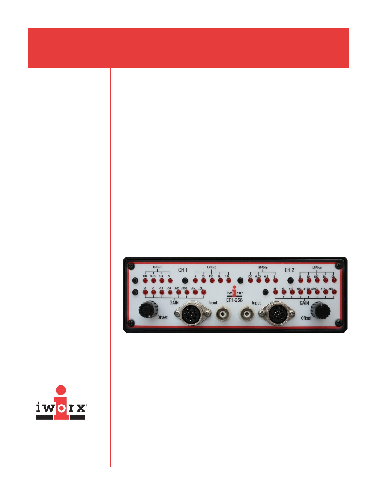
Front Panel
The ETH-256 is divided into two units or channels with identical functions that are
capable of making low noise, AC-coupled recordings of bioelectric potentials, or
DC-coupled transducer recordings.
Each channel can provide ±5.0V of excitation at 50 mA, adequate for most
commonly used transducers. In addition, customers may specify adapter cables to
accommodate Grass, Gould, or HP sensors.
High-Pass Filter [HPF(Hz)]
The high-pass filter has four positions. Each time the button is pushed, the filter
advances, in step-wise fashion, to the next filter as indicated by the LEDs. The DC
position directly couples the input to the amplifier and is used for measuring from
2
wheatstone bridge-style transducers or other ground-referenced sensors requiring
impedance conversion, such as pH electrodes or ion-selective electrodes (ISEs).
Page 3

ETH-256 Amplifier with Isolated Headstage
There are three AC-coupled, high-pass filter settings: 0.03, 0.3, and 3 Hz. For
ECG, EEG, and EOG recordings, 0.3 Hz is normally used; for EMGs, 3 Hz is
commonly used. The result of using a high-pass filter with a higher value is the
creation of a more stable recording baseline; contributions from body movement or
breathing can be removed with high-pass filter settings.
Low-Pass Filter [LPF(Hz)]
The low-pass filter control sets the upper limit of frequencies measurable by the
ETH-256. The setting labeled 10k offers a maximum frequency response of about
10k Hz. Other settings may be chosen to limit noise. For example, the 50 Hz filter
removes signals above 50 Hz. AC noise at 60 Hz, the most common source of
electrical interference, would be filtered from the recording along with any other
frequencies above 50 Hz. For very slow (low frequency) signals, such as the
output of a force or pressure transducer, the 5 Hz setting will provide the quietest
recording.
Gain
The gain of each channel on the ETH-256 can be adjusted independently. This
allows very small signals to be amplified before presentation to the display device.
The gain control push-button allows you to select among eight preset multipliers:
x1, x5, x10, x50, x100, x500, x1k, and x5k.
iWorx Systems, Inc.
www.iworx.com
Input Offset
The position of the recording baseline, in either Bridge (DC) or Bio (0.03, 0.3 and 3
Hz) mode, can be moved up or down by using the Input Offset knob. This control is
very important in Bridge mode where the output of a transducer may need to be
zeroed, or the maximum height of the recording display area may need to be set.
Input
The input connectors are either BNC connectors for single-ended devices, or DIN8
connectors for transducers, isolation pods, headstages, and current-to-voltage
adapters.
Rear Panel
3
Page 4

ETH-256 Amplifier with Isolated Headstage
The BNC output connectors for the ETH-256 are located on the rear panel. They
can be cabled to your data acquisition system using a BNC-BNC cable. The power
transformer input and the power switch are also found on the rear panel of the
ETH-256.
The C-ISO-256 Isolated Headstage
The ETH-256C comes with a 3-lead isolated headstage (C-ISO-256). This cable
may be used on either channel of the ETH-256. The C-ISO-256 contains an
optically isolated output stage.
The C-ISO-256 amplifies the signal x400, and the output should be between 0.5
and 5VDC. There is a switch on the isolation unit that sets the low-pass filter to 25
Hz (useful in ECG and EEG recordings) or 2.5k Hz (useful when recording EMGs).
Technical Data and Specifications
SPECIFICATIONS - ETH-256
Number of channels 2
Operational Modes Bridge, Biopotential (ECG, EMG, EOG, EEG)
Gain x1, x5, x10, x100, x500, x1K, x5K (push-button
selectable)
Low-pass Filter 4-pole active filters at 5, 50, 150, 2K and 10K Hz
High-pass Filter 4-pole active filters at DC, 0.03, 0.3, and 3 Hz
Input Impedance 10 gigohm
Output Impedance 10 ohm
CMR 100dB @ 60 Hz
Offset Range ± 5VDC
Input Range ± 5VDC
Input Connectors DIN8 and BNC
Isolation Optical with optional C-ISO-256C headstage
Noise <10mV (RTI) / < 2µV (RTO)
Transducer Excitation
Voltage ± 5VDC
Current 50mA / channel
Interface 12VAC wall adapter
Power 5VDC, 2.6 amp
iWorx Systems, Inc.
www.iworx.com
4
Enclosure Aluminum (CE compliant)
Dimensions 17 cm W, 28 cm D(including connectors), 6 cm H
Part Number ETH-256, ETH-256C (with C-ISO-256)
Page 5

ETH-256 Amplifier with Isolated Headstage
SPECIFICATIONS - C-ISO-256
Isolation Optical
Gain X400
High-pass Filter 0.05 Hz
Low-pass Filter 25 Hz or 2.5k Hz selectable
Amplifier Connector DIN8
Signal Connectors DIN 42-802 Type ST
Part Number C-ISO-256
How to Use the ETH-256
Operation in Bridge Mode
Input
On the ETH-256, the input for transducers, pods, and adapters is a standard eightpin DIN socket located on the front panel of the unit. A list of wiring schemes for
iWorx DIN8s and other common connectors is found in Tech Center of the User
Area of the iWorx website: www.iworx.com.
iWorx Systems, Inc.
www.iworx.com
Offset
Use the 10-turn offset knob on the front panel of the ETH-256 to control the precise
position of the baseline, while allowing inherent offsets of the transducer to be
nulled.
Operation of devices with excitation voltages
Once transducers, pods, or adapters are wired for the correct configuration of the
input of the ETH-256, these devices will be supplied with excitation voltages
(±5VDC), inputs (+ or -) for the differential amplifier, and a circuit ground.
The output of the transducer can now be viewed (at the selected gain) from the
BNC connector of the output on the rear panel. Adjust the offset as necessary.
Using a strain gauge transducer with the ETH-256:
1) After the transducer has been correctly fitted with a DIN8 connector and
attached to the appropriate input socket on the amplifier, connect the output
BNC on the ETH-256 to the input of your iWorx data acquisition device.
2) Set the ETH-256 gain to x1, the low-pass filter to 5 Hz, and the high-pass filter
to DC.
3) Observe the output of the ETH-256 on your computer. Confirm that the
baseline position can be changed by turning the input offset knob for this
channel. Adjust the baseline to zero volts.
4) If you cannot see the baseline move when you turn the input offset knob, try
increasing the amplifier gain. A word about increasing gain: it’s possible that
your software will also amplify and/or position a signal. To avoid confusion, use
5
only one set of controls to adjust gain or offset once the signal is positioned.
Page 6

ETH-256 Amplifier with Isolated Headstage
5) Continue to increase the gain until you can easily position the line with the
input offset control. If you cannot see a signal on your recorder or if the signal
is “pegged” all the way to the top or bottom of the software range, disconnect
the transducer immediately and refer to the troubleshooting section of this
manual.
6) Now that you have your signal positioned, deflect your transducer by an
amount appropriate to your experiment. For example, if you have connected a
blood pressure transducer, apply approximately 250mmHg, or if you have
connected a force transducer, hang a weight from it which is approximately
equal to the maximum force you expect to see.
7) Does the trace go off the screen? If so, reduce the gain. If the deflection on the
screen appears small (less than 20% of the full screen or paper), increase the
gain. You are now ready to calibrate the transducer. Refer to the manual that
came with your iWorx data acquisition system for the best procedure to
accomplish this.
Operation of devices without resistive bridges, or excitation voltages
The high input impedance of the ETH-256 in Bridge mode makes it useful for
transducer types other than transducers with resistive bridges. Piezoelectric, pH, or
any device with a signal output less than ±5VDC can be applied to the inputs in
differential or single-ended modes. Be careful to shield the cable and source when
using high-impedance devices.
iWorx Systems, Inc.
www.iworx.com
Using a pH sensor with the ETH-256:
1) Set the ETH-256 gain switch to x1 and the low-pass filter setting to 50 Hz.
2) Put the electrode in pH7.0 buffer. Observe the output of the ETH-256 on your
recording device. Use the input offset to adjust the output to zero.
3) Use a pH10 buffer to do the second measurement. Select a gain on the ETH256 that allows the deflection from zero produced by the change of buffer to be
seen. Refer to the manual that came with your iWorx data acquisition device for
the best procedure to accomplish this.
Operation in Bio Mode
With the LED of the 0.03, 0.3, or 3 Hz high-pass filter illuminated, the amplifier is
ready to record biopotentials. Any of these three settings will AC-couple the input to
the amplifier. AC-coupling selectively removes the DC component of signals being
recorded. For example, when recording an ECG, the electrodes placed on the
surface of the skin will generate a relatively small galvanic (steady state) potential
between them. This small galvanic potential is many times the amplitude of the
ECG signal being recorded. If the input is AC-coupled to the amplifier, the galvanic
potential is selectively removed from the complete signal and the ECG signal
remains. All the gain required to record the ECG can now be used. The 0.03, 0.3,
6
or 3 Hz filters will also remove low frequency AC signals, like the artifacts due to
breathing or movement.
Page 7

ETH-256 Amplifier with Isolated Headstage
Control/Setup
Advance the high-pass filter selection so that the 0.3 Hz LED is illuminated and set
the gain to x10. As with the Bridge mode, it is a good idea to use the gain or the
offset adjustments of the ETH-256 to adjust the size and position of the signal
appearing on the screen. Select the 150 Hz low-pass filter if you are recording an
ECG, or 10k Hz if you are recording an EMG.
Using the Isolated Headstage (C-ISO-256)
Connecting the leads
Attach the three color-coded lead wires to the Isolated Headstage. Attach surface
electrodes to the subject. These electrodes should have a snap connector to be
used with the supplied lead wires.
Operation
With the described settings, you should now see the trace slowly approach zero as
the recording begins. This process can take 10 to 15 seconds if the amplifier circuit
has been open for any length of time. Be patient and let the trace settle before you
attempt to adjust the offset. If the trace is noisy or wanders, see the
troubleshooting section of this manual. Note that the isolation unit has a switch on
it that can set the low-pass filter to either 25 Hz or 2.5k Hz. Assuming the trace is
stable and quiet, increase the gain until you can see an acceptable signal. When
used with the C-ISO-256, a gain of x1 set on the front panel will produce an
electrocardiogram of between 0.5 and 5VDC.
iWorx Systems, Inc.
www.iworx.com
The ETH-256 can be used to record signals such as ECG, EMG, EOG, and EEG.
It can also be used to measure potentials directly from muscles and nerves. Using
the appropriate cables and electrodes, it is ideally suited for extracellular
recordings from animal tissue with hook, pin, or suction electrodes.
Recording an ECG with the ETH-256C:
1) Plug the C-ISO-256 isolated headstage into the input socket for Channel 1.
2) Using an alcohol prep or alcohol-soaked cotton ball, lightly abrade the skin on
the underside of each forearm and on the back of the calf near the ankle. After
the skin dries, attach a disposable, adhesive-backed electrode to each of the
sites.
3) Connect the green lead (ground) to the electrode on the right leg. Connect the
red lead (+) to the right arm and the black lead (-) to the left arm.
4) Have the subject sit quietly in a chair with his or her forearm resting on a table
with palm turned upward and finger flexor muscles relaxed.
5) Start recording. The output seen on Channel 1 is a “Lead 1" ECG. Increase
the gain until the form of the ECG can be clearly seen.
7
Page 8

ETH-256 Amplifier with Isolated Headstage
Recording an EMG with the ETH-256C:
1) Plug the C-ISO-256 isolated headstage into the input socket for Channel 1.
2) Using an alcohol prep or alcohol-soaked cotton ball, lightly abrade the skin
on the underside of one forearm. After the skin dries, attach disposable,
adhesive-backed electrodes to the upper part of the forearm, the middle of
the forearm, and the wrist.
3) Connect the green lead (ground) to the electrode on the wrist. Connect the
red lead (+) to the upper portion of the forearm with the greatest diameter
and the black lead (-) to the middle of the forearm.
4) Have the subject sit quietly in a chair with his or her forearm resting on a
table with palm turned upward and finger flexor muscles relaxed.
5) Start recording. After five seconds, the subject should gently contract his or
her finger flexor muscles to make a fist. The subject should hold this clench
for two seconds, then relax again for two seconds.
6) Continue to record, as the subject alternates periods of progressively
stronger contractions with relaxation. Stop recording when the contraction
reaches a maximum.
iWorx Systems, Inc.
www.iworx.com
Troubleshooting
Problem: In DC mode, the trace remains maxed at the top or bottom, and turning
the offset control has no effect.
Solution: Check that the transducer is not overloaded and that the gain is not set
too high. It may be that you are amplifying the signal too much. If, instead, your
transducer is not reacting to a large pressure or force, the connector on the
transducer may need to be checked to confirm that the wiring is correct and that
there are no shorts.
Problem: In DC mode, when using the ETH-256 with data acquisition devices
sampling at low speed, a slow sinusoidal drift appears.
Solution: Sinusoidal drift observed when using digital recording devices is almost
always due to aliasing of higher frequency noise. The most likely cause in this case
is the building AC. Use the 50 Hz low-pass filter on the ETH-256 and any AC notch
filter that may be available on your recording software to minimize or remove this
artifact.
Problem: When using a high-pass filter other than DC, the signal is noisy and
wanders.
Solution: Noise in the recording of biopotentials is frequently from the power lines
in the room. Normally the differential properties of the amplifier can remove it, but
this becomes difficult if the electrode connection to the subject is of high or variable
resistance. Make sure that surface electrodes are securely fastened to the subject
by gently abrading the skin surface where the electrode will be attached with some
8
nylon scrubbing material. Be sure to use enough electrode gel if you are using
silver (reusable) electrodes.
Page 9

ETH-256 Amplifier with Isolated Headstage
Problem: The offset works and you can see the trace, but testing the transducer
causes no change in the signal.
Solution: Make sure that you are using enough gain to see the changes produced
by your transducer or by an ECG/EMG. Remember these signals can be just a few
millivolts. If you are using the 10V scale you won't see small changes.
For any problem, don't overlook obvious causes. Are the amplifier and recorder
connected to a working outlet? Are you adjusting the switches and controls on the
correct channel? Are you sure about the connection to your data acquisition
system?
iWorx Systems, Inc.
www.iworx.com
9
iWorx Systems, Inc. 62 Littleworth Road, Dover, New Hampshire 03820
(T) 800-234-1757 / 603-742-2492 (F) 603-742-2455
 Loading...