

Page 1
BP-100/102 Intravascular Blood Pressure
Transducer
Technical
Note
BP-100/102
iWorx Systems, Inc.
www.iworx.com
LabScribe is a trademark of
iWorx Systems, Inc.
©2015 iWorx Systems, Inc.
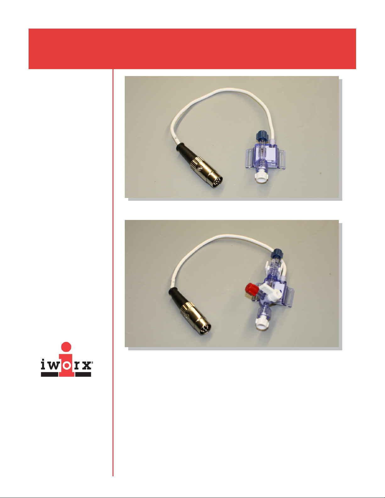
BP-102
Overview
The BP-100/102 Intravascular Blood Pressure Transducer is a clinical blood
pressure transducer modified for use with digital recording equipment in research
applications. It consists of an active element and a separate (included) molded 5 ft.
extension cable. Although the elements are rugged and will stand up to repeated
use, they are not permanent. Replacement elements can be purchased directly
from iWorx Systems, Inc.
The BP-102 integrates a 3cc flush device and stopcock.
The sensor employed in this blood pressure (BP) transducer, and all disposable BP
transducers, is a strain gauge. The pressure output of the gauge is linear. This
makes transducer calibration very straightforward.
Page 2

BP-100/102 Intravascular Blood Pressure
Transducer
On the BP-100, the transducer element is open at both ends. One end is typically
connected to a blood vessel with a piece of heparinized PE tubing. The other end
of the element is connected through a 3-way stopcock to a syringe which is used
for flushing the transducer and the lines. The BP-102 has a pinch valve on one end
for flushing the device; the blood vessel tubing should be connected to the 3-way
stopcock on the other end, To accurately report pressure, these transducers must
be completely filled with fluid. Bubbles in the transducer or the lines will produce
inaccurate results.
How to Use the BP-100/102
Equipment Setup
1) Plug the connector of a DIN8 extension cable into one of the DIN8 transducer
inputs of an iWorx data acquisition unit or amplifier. Plug the DIN8 connector of
the BP-100/102 into the DIN8 extension cable.
2) Attach the cannula from the subject's artery to either end of the BP-100 or to
the 3-way stopcock on the BP-102. The cannula, stopcock, and transducer
should be filled with heparinized saline solution to prevent clotting.
iWorx Systems, Inc.
www.iworx.com
Start the Software
When using an iWorx data acquisition system with its own DIN8 transducer inputs,
or an iWorx amplifier like the ETH-256 or the ETH-401, coupled to an iWorx data
acquisition device:
1) Open LabScribe by double-clicking on the desktop shortcut.
2) When the program opens, select Preferences from the Edit menu (or from the
LabScribe menu on a Macintosh). Click on the Channel button. In the
Channel preferences dialog, name the channel to which the BP-100/102, or
the amplifier supporting the BP-100/102, is connected. Set the
Mode/Function for this channel to DIN8. Set the sampling rate and display
time. Click OK.
Calibration
There are two ways to calibrate the BP-100/102.
Method 1: Manometer Calibration
1) Turn the valve of the 3-way stopcock so that the line going to the animal is
closed.
2) Connect a manometer to the open port on the 3-way stopcock.
3) Check that the pressure on the manometer is 0 (zero) mmHg. Start recording.
4) Pressurize the manometer to 100 mmHg and adjust the range displayed on the
data acquisition device so that the change in the signal from 0 to 100 mmHg
can be seen easily.
5) Mark the record to indicate 100mmHg.
Page 3

BP-100/102 Intravascular Blood Pressure
Transducer
6) Bleed pressure from the manometer until it drops back to 50mmHg. Mark the
record again.
7) Stop recording the signal.
8) Position the section of the recording that contains the step from 100mmHg to
50mmHg in the center of the screen.
9) Position one of the blue cursors in the Main window in the 100mmHg section
of the recording.
10) Position the second cursor in the 50mmHg section.
11) Right-click on the recording window of the channel to which the BP-100/102 is
connected.
12) Select Units.from the right-click menu of the recording channel.
13) Select 2 point calibration from the Units Conversion dialog. Notice that the
voltages from the positions of the cursors are automatically entered into the
left side data boxes.
14) Enter the two pressures, 50 and 100, used in the calibration recording in the
corresponding boxes on the right side of the conversion equations.
15) Enter the name of the units, mmHg, in the box below the pressures.
16) Put a check mark in the box next to Apply Units to all blocks.
17) Click on the OK button in the lower right corner of the window to activate the
units conversion.
iWorx Systems, Inc.
Method 2: Conversion Factor
The output of the transducer element used in the BP-100/102 has a very high
degree of linearity. The output of the BP-100/102 is 5 microvolts (μV) per millimeter
of mercury (mmHg) for every volt of excitation voltage applied (V). If 10 Volts (±5V)
are applied to the BP-100/102 as the excitation voltage, the output of the BP100/102 is 50 microvolts per millimeter of mercury (μV/mmHg) at 1X gain.
When the BP-100/102 is used with a transducer input of an iWorx data acquisition
unit or the ETH-256 or ETH-401 amplifier, a gain of x400 is automatically applied to
the output signal. For example, if a BP-100/102 is connected to a DIN8 transducer
input of the data acquisition unit, a 20mV signal displayed on the LabScribe Main
window is equal to 1mmHg:
5μV/V applied/mmHg x 10V applied = 50μV/mmHg
50μV/mmHg x X400 gain = 20mV/mmHg
Since the voltage applied to the transducer by any of these devices is 10V, the
inverse of this factor can be used to convert the voltage output of the BP-100/102
to pressure:
(1000mV/V)/(20mV/mmHg) = 50mmHg/V recorded.
www.iworx.com
Page 4

BP-100/102 Intravascular Blood Pressure
Transducer
The BP-100/102 can be calibrated by using the calibration factor, 50mmHg/V, on
the Units Conversion window of the recording channel, as follows:
1) Record a few seconds of data from the BP-100/102.
2) Right-click on the recording window of the channel to which the BP-100/102 is
connected.
3) Select Units...from the right-click menu of the recording channel.
4) Select Slope & Offset from the menu in the upper left corner of the Units
Conversion window.
5) In the box to the right of slope, enter the number 50 if the BP-100/102 is
connected to an iWorx data acquisition unit with DIN 8 inputs, or an ETH-256 or
ETH-401 with its gain set at X1. If additional gain is applied to the output of the
BP-100/102 when it is used with an ETH-256, the slope is equal to 50 divided
by the gain factor. For example, if a gain of x5 is applied to the output of the BP100/102, the conversion factor entered as the slope is 10.
6) In the box to the right of offset, enter the number 0.
7) In the box to the right of Name, enter mmHg.
8) Put a check mark in the box next to Apply Units to all blocks.
9) Click on the OK button in the lower right corner of the window to activate the
units conversion.
iWorx Systems, Inc.
Care
1) After using the BP-100 transducer, flush out the element using a syringe that is
attached to the transducer with a 3-way stopcock and filled with distilled water.
Open the 3-way stopcock on the transducer to the air and allow all the parts of
the element to dry. The BP-102 includes an integrated 3cc flush device and
stopcock. Open the pinch valve at the far end while flushing water through the
transducer.
2) During testing or use, do not apply too much pressure to the sensor. Pressures
of 500 mmHg or more can fracture the plastic enclosure and cause leaks.
3) The removable caps supplied with the transducer element are only dust covers;
these caps are not airtight.
4) These transducers are nonlinear at pressures less than 7mmHg.
www.iworx.com
Page 5

BP-100/102 Intravascular Blood Pressure
Transducer
Technical Data and Specifications
SPECIFICATIONS
Operating Pressure +0.50 to +300 mmHg
Over Pressure -500 to +100 mmHg
Sensitivity 5 μV/V/mmHg at X1 Gain
Excitation Voltage +5
Temperature Effect +0.25 mmHg/oC
Impedance <900 W
iWorx Systems, Inc.
www.iworx.com
iWorx Systems, Inc. 62 Littleworth Road, Dover, New Hampshire 03820
(T) 800-234-1757 / 603-742-2492 (F) 603-742-2455
 Loading...