


ZPCsp and ZPC64 Barebone Hardware Quick Installation Guide…….....1-10
Mini-PC ZPCsp et ZPC64 Guide d'installation rapide du materiel…….…11-22
ZPCsp und ZPC64 Barebone Kurzanleitung für Hardware-Installation….23-34
Equipos Barebone ZPCsp y ZPC64 Guía de Instalación Rápida de Hardware....35-46
ZPCsp 及び ZPC64 ベアボーン ハードウ ェ ア クイ ッ ク インスト ールガイド ….....47-60
ZPCsp 與 ZPC64 準系統 硬體快速安裝指南……………………………..61-70
ZPCsp 与 ZPC64 准系统 硬件快速安装指南……………………………..71-80
Barebone ZPCsp e ZPC64 Guida all’installazione rapida dell’hardware………..81-90
ZPCsp 및 ZPC64 베어본 하드웨어 요약 설치 설명서………………..91-101


ZPCsp and ZPC64 Barebone
Hardware Quick Installation Guide
Version 1.0
FB24628701

IWILL User’s Manual
2 User’s Manual
Always turn the power off before you open the system or connect your computer to
peripheral equipment. Otherwise, damage may occur to the integrated circuits in your
computer. Electrostatic discharge (ESD) may damage HDDs and other components.
Follow the procedures described here only at an ESD workstation. Ground yourself by
maintaining continuous contact with an unpainted metal portion of the chassis while
installation.
Information in this document is subject to change without notice. ©2004 IWILL
Corporation All rights reserved. Reproduction in any manner whatsoever without the
written permission of IWILL Corp. is strictly forbidden. IWILL and the IWILL logo are
trademarks of IWILL; IWILL disclaims proprietary interest in the marks and names of
others. May 2004

IWILL ZDMA User’s Manual
User’s Manual 3
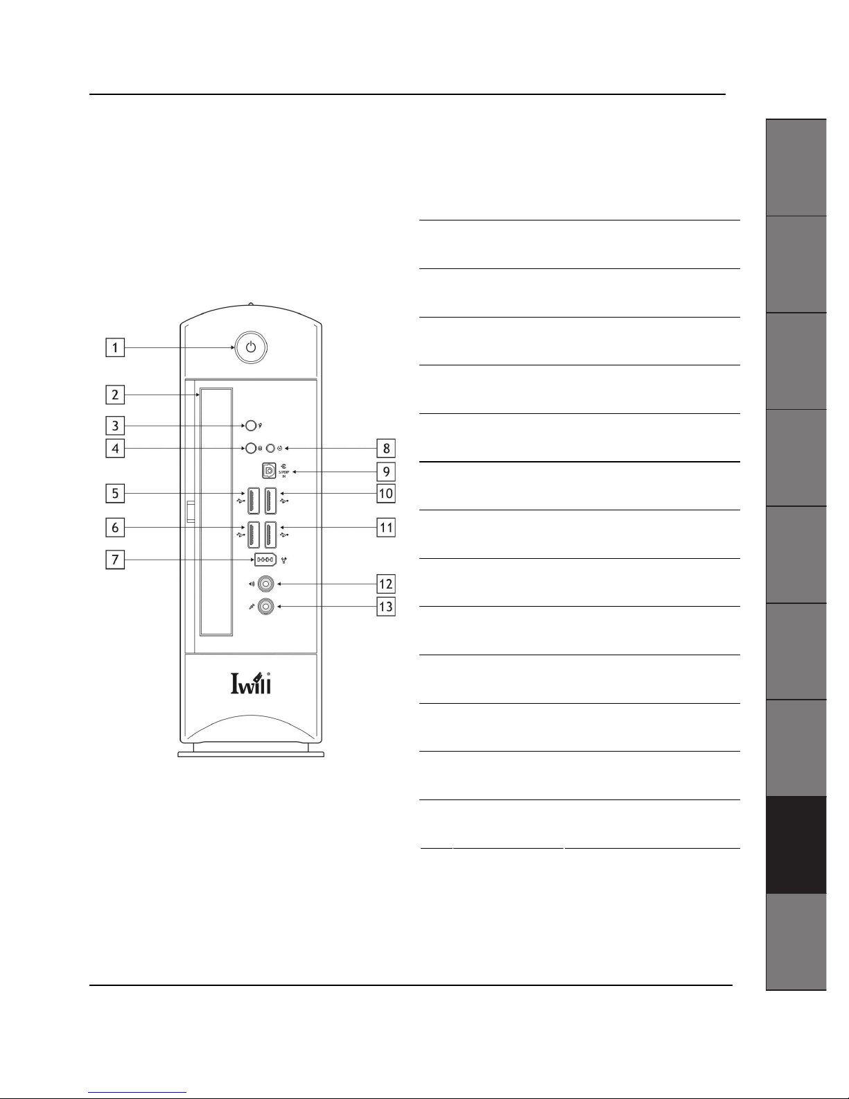
ZPCsp Front and Rear Panel Features:
The front panel of ZPCsp features: a slim line bay for optical disk drive, Microphone, Earphone, SPDIF Out, 6-pin Firewire
jacks, and USB2.0 connectors
1 Power switch Turns the computer on and off..
2 Optical drive Slimline drive bay for optical drive
3 System Indicator
The indicator light is amber when the
computer is placed in Stand by mode
4 HDD access indicator
Light is amber while reading and writing
data from and to the hard disk.
5 Universal Serial Bus 1
Connections for compatible high/ full/
low-speed USB devices.
6 Universal Serial Bus 2
Connections for compatible high/ full/
low-speed USB devices.
7 6-pin IEEE1394
Connection for a compatible digital
device.
8 System Reset Reset the System
9 SPDIF In Connection for SPDIF Input
10 Universal Serial Bus 3
Connections for compatible high/ full/
low-speed USB devices.
11 Universal Serial Bus 4
Connections for compatible high/ full/
low-speed USB devices.
12 headphone connector Connection for a headphone
13 microphone connector Connection for microphone
The front panel of your ZPC Computer enables access to drives, ports and jacks that enable you to connect compatible
peripheral devices.
ʳʳ ʳ ʳ ʳ
English
Français Deutsch Español
ᣣᧄ⺆
ᣣᧄ⺆
ᣣᧄ⺆
ᣣᧄ⺆
᧯խ֮
᧯խ֮
᧯խ֮
᧯խ֮
ㅔԧЁ᭛
ㅔԧЁ᭛
ㅔԧЁ᭛
ㅔԧЁ᭛
Italiano
䞲ῃ㠊
䞲ῃ㠊
䞲ῃ㠊
䞲ῃ㠊
G
G
G
G
ʳ
ʳ

IWILL User’s Manual
4 User’s Manual
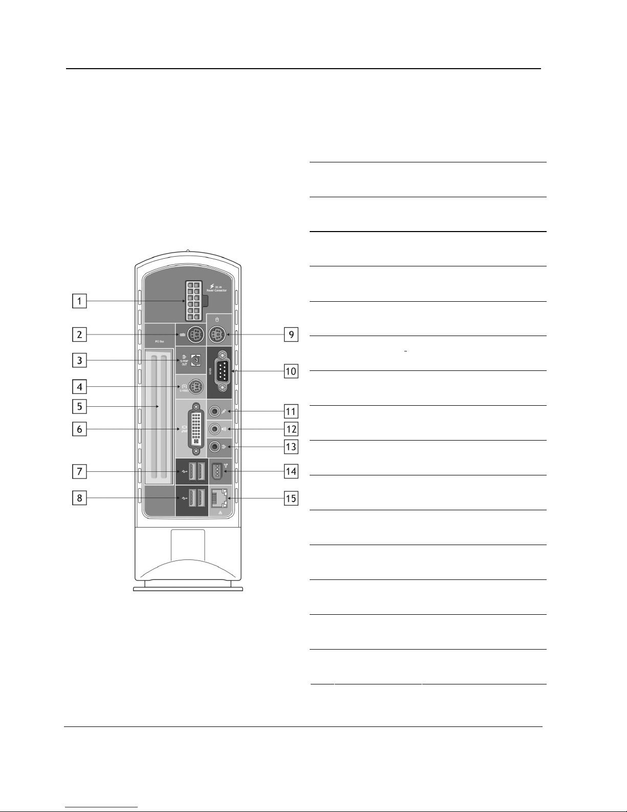
ZPCsp Rear Panel Features:
The back panel of your ZPC-AP contains the ports for supplied and optional accessories. The icons on the back panel
locate and identify the ports on your computer.
1 Power connector
Connection for the external power
supply.
2 Keyboard port Connection for a PS/2 keyboard.
3 SPDIF Out Connection for SPDIF Output
4 S-video In jack Connection for an S-video cable
5 Empty PCI bracket Connections for PCI devices.
6 Monitor (DVI) port1 Connection for a DVI monitor.
7 Universal Serial Bus 5
Connections for compatible high/ full/
low-speed USB devices.
8 Universal Serial Bus 6
Connections for compatible high/ full/
low-speed USB devices.
9 Mouse port Connection for a PS/2 mouse.
10 Serial connector Connections for serial devices.
11 Microphone In jack Connection for a microphone
12 line-out connector
Connection for the supplied
sub-woofer, or optional speakers or
headphones.
13 line-in connector Connection for an audio device.
14 6-pin IEEE1394
Connection for a compatible digital
device.
15 Ethernet port
Connection for a 10BASE-T/
100BASE-TXBASE-TX Ethernet.

IWILL ZDMA User’s Manual
User’s Manual 5
ZPC
64
Front and Rear Panel Features:
The front panel of ZPC64 features: a slim line bay for optical disk drive, Microphone, Earphone, SPDIF Out, 6-pin Firewire
jacks, and USB2.0 connectors
1 Power switch Turns the computer on and off..
2 Optical drive Slimline drive bay for optical drive
3 System Indicator
The indicator light is amber when the
computer is placed in Stand by mode
4 HDD access indicator
Light is amber while reading and writing
data from and to the hard disk.
5 Universal Serial Bus 1
Connections for compatible high/ full/
low-speed USB devices.
6 Universal Serial Bus 2
Connections for compatible high/ full/
low-speed USB devices.
7 6-pin IEEE1394
Connection for a compatible digital
device.
8 System Reset Reset the System
9 SPDIF In Connection for SPDIF Input
10 Universal Serial Bus 3
Connections for compatible high/ full/
low-speed USB devices.
11 Universal Serial Bus 4
Connections for compatible high/ full/
low-speed USB devices.
12 headphone connector Connection for a headphone
13 microphone connector Connection for microphone
The front panel of your ZPC Computer enables access to drives, ports and jacks that enable you to connect compatible
peripheral devices.
ʳʳ ʳ ʳ ʳ
English
Français Deutsch Español
ᣣᧄ⺆
ᣣᧄ⺆
ᣣᧄ⺆
ᣣᧄ⺆
᧯խ֮
᧯խ֮
᧯խ֮
᧯խ֮
ㅔԧЁ᭛
ㅔԧЁ᭛
ㅔԧЁ᭛
ㅔԧЁ᭛
Italiano
䞲ῃ㠊
䞲ῃ㠊
䞲ῃ㠊
䞲ῃ㠊
G
G
G
G
ʳ
ʳ

IWILL User’s Manual
6 User’s Manual
ZPC
64
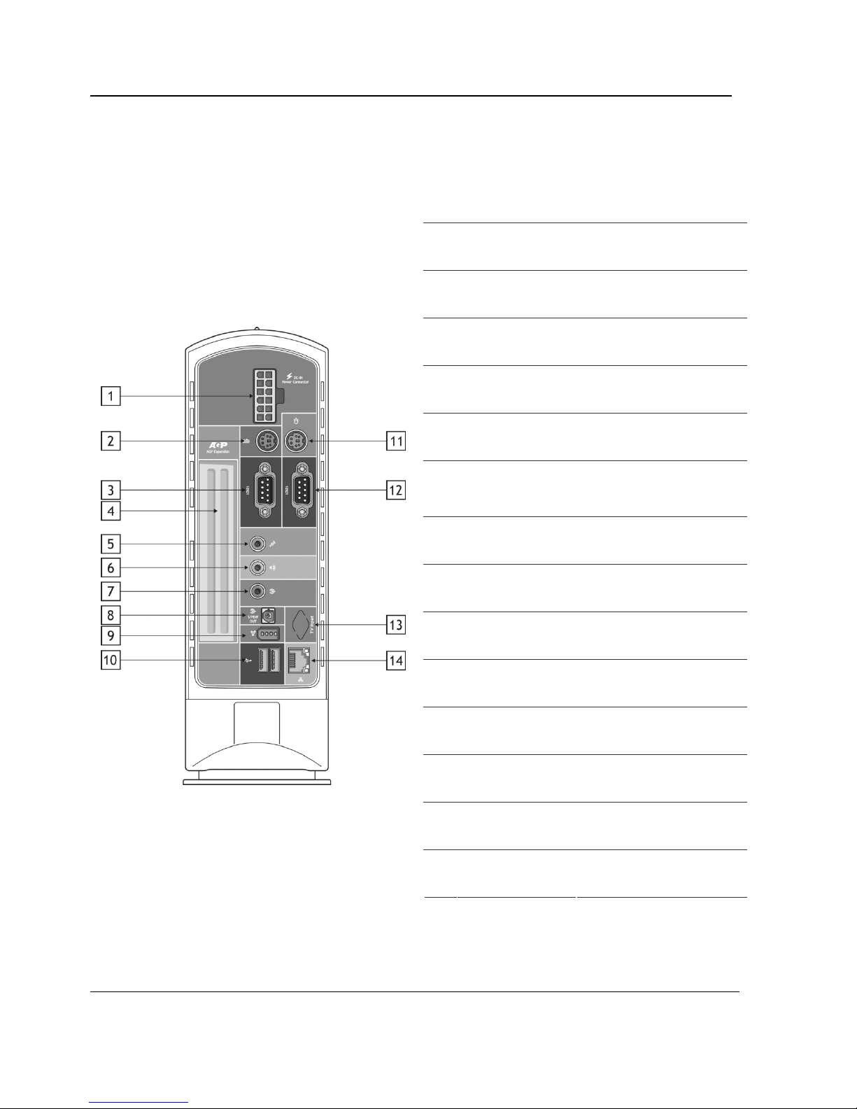
Rear Panel Features:
The back panel of your ZPC64 contains the ports for supplied and optional accessories. The icons on the back panel locate
and identify the ports on your computer.
1 Power connector
Connection for the external power
supply.
2 Keyboard port Connection for a PS/2 keyboard.
3 Serial connector Connections for serial devices.
4 Empty AGP bracket For AGP 8X Card expansion
5 Microphone In jack Connection for a microphone
6 line-out connector
Connection for the supplied
sub-woofer, or optional speakers or
headphones.
7 line-in connector Connection for an audio device.
8 SPDIF Out Connection for SPDIF Output
9 6-pin IEEE1394
Connection for a compatible digital
device.
10 Universal Serial Bus 5
Connections for compatible high/ full/
low-speed USB devices.
11 Mouse port Connection for a PS/2 mouse.
12 Serial connector Connections for serial devices.
13
TV In Connector
(Optional)
Connection for an mini-PCI TV Tunner
Card. (Optional)
14 Ethernet port
Connection for a 10BASE-T/
100BASE-TXBASE-TX Ethernet.

IWILL ZDMA User’s Manual
User’s Manual 7
Push down the latch to release. Separate the base set it aside.
Open the front pane. Push the latch to release. Lift
the panel with one hand while holding the system
portion with your other hand.
Remove the screw from the front panel.
Remove front bezel by gently detaching the two
internal hooks
Remove the three screws on each marked location
as shown.
ʳʳ ʳ ʳ ʳ
English
Français Deutsch Español
ᣣᧄ⺆
ᣣᧄ⺆
ᣣᧄ⺆
ᣣᧄ⺆
᧯խ֮
᧯խ֮
᧯խ֮
᧯խ֮
ㅔԧЁ᭛
ㅔԧЁ᭛
ㅔԧЁ᭛
ㅔԧЁ᭛
Italiano
䞲ῃ㠊
䞲ῃ㠊
䞲ῃ㠊
䞲ῃ㠊
G
G
G
G
ʳ
ʳ

IWILL User’s Manual
8 User’s Manual
Pry the cover open with your thumb Slowly lift out the cover from the chassis.
Use the thumbs to dislodge hooks that are molded with
cover. Slowly lift out the cover from the chassis.
Separate the case cover
Remove the EMI gaskets by releasing screws. Disconnect the CPU fan cable from the assembly to
the fan connector.

IWILL ZDMA User’s Manual
User’s Manual 9
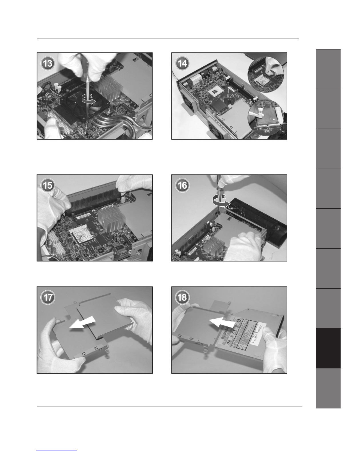
Remove heat sink by unscrewing the each screw on
the corner of the cooling fan.
Open the socket handle. Install the CPU and close the
socket handle. Apply thermal cream to the top of the
processor.
Insert memory module into socket and secure it with
the retaining arms.
Remove the optical drive holder.
Assemble the inner bracket to drive holder. Assemble the slimline optical drive to drive holder and
inner bracket.
ʳʳ ʳ ʳ ʳ
English
Français Deutsch Español
ᣣᧄ⺆
ᣣᧄ⺆
ᣣᧄ⺆
ᣣᧄ⺆
᧯խ֮
᧯խ֮
᧯խ֮
᧯խ֮
ㅔԧЁ᭛
ㅔԧЁ᭛
ㅔԧЁ᭛
ㅔԧЁ᭛
Italiano
䞲ῃ㠊
䞲ῃ㠊
䞲ῃ㠊
䞲ῃ㠊
G
G
G
G
ʳ
ʳ

IWILL User’s Manual
10 User’s Manual
Secure the each screw on the corner of the CDROM. Slide the drive assembly back into its place.
Connect the cable to the connector on the CDROM Use your thumbs to pull on internal hooks one by one.
Push chassis cover towards the base.
Replace the cover to the chassis. Make sure the each corner is well aligned to the case.

Mini-PC ZPCsp et ZPC
64
Guide d'installation rapide du matériel
Version 1.0

IWILL Manuel de l'utilisateur
12 Manuel de l'utilisateur
Mettez toujours le système hors tension avant de l'ouvrir ou de connecter sur votre
ordinateur un équipement périphérique. Sinon, vous risquez d'endommager les circuits
intégrés de votre ordinateur. Les décharges électrostatiques (ESD) risquent
d'endommager les disques durs et les autres composants. N'appliquez les procédures
décrites ci-dessous que sur un poste de travail ESD. Reliez-vous à la terre en maintenant
un contact continu avec une portion métallique non peinte du châssis pendant
l'installation.
Les informations présentes dans ce document sont sujettes à modification sans préavis.
©2004 IWILL Corporation Tous droits réservés. Toute reproduction par quelque procédé
que ce soit sans la permission écrite de IWILL Corp. est strictement interdite. IWILL et le
logo IWILL sont des marques de commerce de IWILL; IWILL déclare n'avoir aucun intérêt
propriétaire dans les marques et noms des tiers. Mai 2004

IWILL ZDMA Manuel de l'utilisateur
Manuel de l'utilisateur 13
Fonctionnalités sur les panneaux avant et arrière du ZPCsp :
Fonctionnalités du panneau avant du ZPCsp : une baie étroite pour unité de disque optique, microphone, casque audio,
sortie SPDIF, prises FireWire 6 broches, et connecteurs USB2.0
1
Interrupteur
d'alimentation
Permet d'allumer et d'éteindre
l'ordinateur.
2 Unité optique Baie étroite pour unité optique
3 Indicateur système
L'indicateur lumineux est orange lorsque
l'ordinateur est placé en mode Veille
4
Indicateur d'accès au
disque dur
L'indicateur est orange lorsque des
données sont lues ou écrites sur le
disque dur.
5 Bus USB 1
Connexions pour les périphériques USB
compatibles haute/ pleine/ basse
vitesse.
6 Bus USB 2
Connexions pour les périphériques USB
compatibles haute/ pleine/ basse
vitesse.
7 IEEE1394 6 broches
Connexion pour un périphérique
numérique compatible.
8
Réinitialisation du
système
Permet de réinitialiser le système
9 Entrée SPDIF Connexion pour Entrée SPDIF
10 Bus USB 3
Connexions pour les périphériques USB
compatibles haute/ pleine/ basse
vitesse.
11 Bus USB 4
Connexions pour les périphériques USB
compatibles haute/ pleine/ basse
vitesse.
12
Connecteur pour
casque audio
Connexion pour un casque audio
13 connecteur microphone Connexion pour microphone
Le panneau avant de votre ordinateur ZPC vous permet d'accéder aux unités, aux ports et aux prises qui vous permettent
de connecter des équipements périphériques compatibles.
ʳʳ ʳ ʳ ʳ
English
Français Deutsch Español
ᣣᧄ⺆
ᣣᧄ⺆
ᣣᧄ⺆
ᣣᧄ⺆
᧯խ֮
᧯խ֮
᧯խ֮
᧯խ֮
ㅔԧЁ᭛
ㅔԧЁ᭛
ㅔԧЁ᭛
ㅔԧЁ᭛
Italiano
䞲ῃ㠊
䞲ῃ㠊
䞲ῃ㠊
䞲ῃ㠊
G
G
G
G
ʳ
ʳ

IWILL Manuel de l'utilisateur
14 Manuel de l'utilisateur
Fonctionnalités du panneau arrière du ZPCsp :
Le panneau arrière de votre ZPC-AP contient les ports pour les accessoires fournis et optionnels. Les icônes sur le panneau
arrière vous permettent de repérer et d'identifier les ports sur votre ordinateur.
1
Connecteur
d'alimentation
Connexion pour l' alimentation externe
alimentation.
2 Port clavier Connexion pour un clavier PS/2.
3 Sortie SPDIF Connexion pour la Sortie Spdif
4 Prise d' entrée S-Vidéo Connexion pour un câble S-Vidéo
5 Support PCI vide Connexions pour périphériques PCI.
6 Port Moniteur (DVI)1 Connexion pour un moniteur DVI.
7 Bus USB 5
Connexions pour les périphériques
USB compatibles haute/pleine/ basse
vitesse.
8 Bus USB 6
Connexions pour les périphériques
USB compatibles haute/pleine/ basse
vitesse.
9 Port souris Connexion pour une souris PS/2.
10 Connecteur série
Connexions pour les périphériques
série.
11 Prise Entrée microphone Connexion pour un microphone
12
connecteur de sortie de
ligne
Connexion pour le subwoofer fourni,
ou pour les haut-parleurs optionnels ou
le casque audio.
13
connecteur d'entrée de
ligne
Connexion pour un périphérique audio.
14 IEEE1394 6 broches
Connexion pour un périphérique
numérique compatible.
15 Port Ethernet
Connexion pour un Ethernet
10BASE-T/ 100BASE-TXBASE-TX.

IWILL ZDMA Manuel de l'utilisateur
Manuel de l'utilisateur 15
Fonctionnalités sur les panneaux avant et arrière du ZPC
64
:
Le panneau avant du ZPC
64
comporte : une baie étroite pour unité de disque optique, microphone, casque audio, sortie
SPDIF, prises FireWire 6 broches, et connecteurs USB2.0
1
Interrupteur
d'alimentation
Permet d'allumer et d'éteindre
l'ordinateur.
2 Unité optique Baie étroite pour unité optique
3 Indicateur système
L'indicateur lumineux est orange lorsque
l'ordinateur est placé en mode Veille
4
Indicateur d'accès au
disque dur
L'indicateur est orange lorsque des
données sont lues ou écrites sur le
disque dur.
5 Bus USB 1
Connexions pour les périphériques USB
compatibles haute/ pleine/ basse
vitesse.
6 Bus USB 2
Connexions pour les périphériques USB
compatibles haute/ pleine/ basse
vitesse.
7 IEEE1394 6 broches
Connexion pour un périphérique
numérique compatible.
8
Réinitialisation du
système
Permet de réinitialiser le système
9 Entrée SPDIF connexion pour Entrée SPDIF
10 Bus USB 3
Connexions pour les périphériques USB
compatibles haute/ pleine/ basse
vitesse.
11 Bus USB 4
Connexions pour les périphériques USB
compatibles haute/ pleine/ basse
vitesse.
12
Connecteur pour
casque audio
Connexion pour un casque audio
13 connecteur microphone Connexion pour microphone
Le panneau avant de votre ordinateur ZPC vous permet d'accéder aux unités, aux ports et aux prises qui vous permettent
de connecter des équipements périphériques compatibles.
ʳʳ ʳ ʳ ʳ
English
Français Deutsch Español
ᣣᧄ⺆
ᣣᧄ⺆
ᣣᧄ⺆
ᣣᧄ⺆
᧯խ֮
᧯խ֮
᧯խ֮
᧯խ֮
ㅔԧЁ᭛
ㅔԧЁ᭛
ㅔԧЁ᭛
ㅔԧЁ᭛
Italiano
䞲ῃ㠊
䞲ῃ㠊
䞲ῃ㠊
䞲ῃ㠊
G
G
G
G
ʳ
ʳ

IWILL Manuel de l'utilisateur
16 Manuel de l'utilisateur
Fonctionnalités du panneau arrière du ZPC
64
:
Le panneau arrière de votre ZPC64 contient les ports pour les accessoires fournis et optionnels. Les icônes sur le panneau
arrière vous permettent de repérer et d'identifier les ports sur votre ordinateur.
1
Connecteur
d'alimentation
Connexion pour l' alimentation externe
alimentation.
2 Port clavier Connexion pour un clavier PS/2.
3 Connecteur série
Connexions pour les périphériques
série.
4 Support AGP vide Pour carte d'extension AGP 8X
5 Prise Entrée microphone Connexion pour un microphone
6
connecteur de sortie de
ligne
Connexion pour le subwoofer fourni,
ou pour des haut-parleurs optionnels
ou un casque audio.
7
connecteur d'entrée de
ligne
Connexion pour un périphérique audio.
8 Sortie SPDIF Connexion pour la Sortie Spdif
9 IEEE1394 6 broches
Connexion pour un périphérique
numérique compatible.
10 Bus USB 5
Connexions pour les périphériques
USB compatibles haute/pleine/ basse
vitesse.
11 Port souris Connexion pour une souris PS/2.
12 Connecteur série
Connexions pour les périphériques
série.
13
Connecteur d'entrée TV
(Optionnel)
Connexion pour une carte TV tuner
mini-PCI. (Optionnel)
14 Port Ethernet
Connexion pour un Ethernet
10BASE-T/ 100BASE-TXBASE-TX.

IWILL ZDMA Manuel de l'utilisateur
Manuel de l'utilisateur 17
Pousser le loquet vers le bas pour déverrouiller. Séparez la base et mettez-la de côté.
Ouvrez le panneau avant. Poussez le loquet pour
déverrouiller. Soulevez le panneau d'une main tout en
tenant la portion système de l'autre main.
Démontez la vis du panneau avant.
Enlevez le cache avant en détachant doucement les deux
crochets internes.
Enlevez les trois vis sur chacun des emplacements
marqués ainsi qu'illustré.
ʳʳ ʳ ʳ ʳ
English
Français Deutsch Español
ᣣᧄ⺆
ᣣᧄ⺆
ᣣᧄ⺆
ᣣᧄ⺆
᧯խ֮
᧯խ֮
᧯խ֮
᧯խ֮
ㅔԧЁ᭛
ㅔԧЁ᭛
ㅔԧЁ᭛
ㅔԧЁ᭛
Italiano
䞲ῃ㠊
䞲ῃ㠊
䞲ῃ㠊
䞲ῃ㠊
G
G
G
G
ʳ
ʳ

IWILL Manuel de l'utilisateur
18 Manuel de l'utilisateur
Forcez avec le pouce pour ouvrir le capot Faites lentement glisser le capot hors du châssis.
Avec les pouces, délogez les crochets qui sont moulés
sur le capot. Faites lentement glisser le capot hors du
châssis.
Séparez le capot du boîtier
Enlevez les joints statiques EMI en enlevant les vis. Déconnectez le câble du ventilateur d'UC de l'ensemble
sur le connecteur de ventilateur.

IWILL ZDMA Manuel de l'utilisateur
Manuel de l'utilisateur 19
Enlevez le dissipateur thermique en dévissant les vis qui se
trouvent
sur les coins du ventilateur de refroidissement.
Ouvrir la poignée du socle. Installez le processeur et
refermez la poignée du socle. Appliquez la crème thermique
sur la face supérieure du processeur.
Insérez le module de mémoire dans le socle et fixez-le
en position avec les bras de retenue.
Démontez le support pour unité optique.
Assemblez le support interne sur le support pour unité. Fixez l'unité optique étroite sur le support pour unité et sur le
support interne.
ʳʳ ʳ ʳ ʳ
English
Français Deutsch Español
ᣣᧄ⺆
ᣣᧄ⺆
ᣣᧄ⺆
ᣣᧄ⺆
᧯խ֮
᧯խ֮
᧯խ֮
᧯խ֮
ㅔԧЁ᭛
ㅔԧЁ᭛
ㅔԧЁ᭛
ㅔԧЁ᭛
Italiano
䞲ῃ㠊
䞲ῃ㠊
䞲ῃ㠊
䞲ῃ㠊
G
G
G
G
ʳ
ʳ

IWILL Manuel de l'utilisateur
20 Manuel de l'utilisateur
Serrez les vis aux coins du lecteur de CD-ROM. Faites glisser l'ensemble de l'unité en position.
Connectez le câble du connecteur sur le lecteur de
CD-ROM)
Avec le pouce, tirez sur les crochets internes l'un après
l'autre. Poussez le capot du châssis en direction de la base.
Remettez le capot en place sur le châssis. Assurez-vous que tous les coins sont bien alignés avec le
boîtier.

IWILL ZDMA Manuel de l'utilisateur
Manuel de l'utilisateur 21
ʳʳ ʳ ʳ ʳ
English
Français Deutsch Español
ᣣᧄ⺆
ᣣᧄ⺆
ᣣᧄ⺆
ᣣᧄ⺆
᧯խ֮
᧯խ֮
᧯խ֮
᧯խ֮
ㅔԧЁ᭛
ㅔԧЁ᭛
ㅔԧЁ᭛
ㅔԧЁ᭛
Italiano
䞲ῃ㠊
䞲ῃ㠊
䞲ῃ㠊
䞲ῃ㠊
G
G
G
G
ʳ
ʳ


ZPCsp und ZPC64 Barebone
Kurzanleitung für Hardware-Installation
Version 1.0

IWILL Bedienungsanleitung
24 Bedienungsanleitung
Schalten Sie immer den Computer aus, bevor Sie ihn öffnen oder ihn an ein
Peripheriegerät anschließen. Andernfalls könnte die internen Schaltungen im Computer
beschädigt werden. Elektrostatische Entladungen könnten die Festplatten und andere
Komponenten beschädigen. Führen Sie die hier beschriebenen Abläufe nur einer
Workstation für elektrostatische Entladungen aus. Verbinden Sie sich mit dem Erdleiter,
indem Sie während der Installation immer in Kontakt mit einem unbemalten Teil des
Gehäuses in Kontakt bleiben.
Änderungen der Informationen in diesem Dokument sind vorbehalten. ©2004 IWILL
Corporation. Alle Rechte vorbehalten. Der Nachdruck, ganz gleich auf welche Weise, ist
ohne schriftliche Genehmigung von IWILL Corp. strengstens verboten. IWILL und das
IWILL-Logo sind Warenzeichen von IWILL; IWILL besitzt kein urheberrechtliches
Interesse an den Marken und Namen anderer Warenzeichen. Mai 2004

IWILL ZDMA Bedienungsanleitung
Bedienungsanleitung 25
Funktionen auf der ZPCsp-Vorderseite und –Rückseite:
Auf der ZPCsp-Vorderseite befinden sich: Ein flacher Einschub für ein optisches Laufwerk, Mikrofoneingang, Ohrhörer-,
SPDIF-Ausgänge, 6-pol. Firewire-Buchsen und USB2.0-Anschlüsse
1 Netztaste Schaltet den Computer ein und aus.
2 Optisches Laufwerk Flacher Einschub für optisches Laufwerk.
3 Systemanzeige
Die Anzeige leuchtet orange, wenn sich der
Computer im Standby-Modus befindet.
4 Festplattenzugriffsanzeige
Leuchtet orange, wenn Daten von der
Festplatte gelesen und auf sie geschrieben
werden.
5 Universal Serial Bus 1
Anschluss für kompatible USB-Geräte mit
hoher/voller/niedriger Geschwindigkeit.
6 Universal Serial Bus 2
Anschluss für kompatible USB-Geräte mit
hoher/voller/niedriger Geschwindigkeit.
7 6-pol. IEEE1394 Anschluss für ein kompatibles Digitalgerät.
8 System-Reset Setzt das System zurück.
9 SPDIF-Eingang Anschluss für SPDIF-Eingang.
10 Universal Serial Bus 3
Anschluss für kompatible USB-Geräte mit
hoher/voller/niedriger Geschwindigkeit.
11 Universal Serial Bus 4
Anschluss für kompatible USB-Geräte mit
hoher/voller/niedriger Geschwindigkeit.
12 Kopfhörerausgang Anschluss für einen Kopfhörer.
13 Mikrofoneingang Anschluss für ein Mikrofon.
Auf der Vorderseite des ZPC-Computers haben Sie Zugriff auf Laufwerk, Anschlüsse und Buchsen, an denen Sie
kompatible Peripheriegeräte anschließen können.
ʳʳ ʳ ʳ ʳ
English
Français Deutsch Español
ᣣᧄ⺆
ᣣᧄ⺆
ᣣᧄ⺆
ᣣᧄ⺆
᧯խ֮
᧯խ֮
᧯խ֮
᧯խ֮
ㅔԧЁ᭛
ㅔԧЁ᭛
ㅔԧЁ᭛
ㅔԧЁ᭛
Italiano
䞲ῃ㠊
䞲ῃ㠊
䞲ῃ㠊
䞲ῃ㠊
G
G
G
G
ʳ
ʳ
IWILL Bedienungsanleitung
26 Bedienungsanleitung
Funktionen auf der ZPCsp-Rückseite:
Auf der Rückseite des ZPC-AP befinden sich Anschlüsse für mitgeliefertes und optionales Zubehör. Anhand der Symbole
auf der Rückseite können Sie die Anschlüsse Ihres Computers lokalisieren und identifizieren.
1 Netzanschluss
Anschluss für die externe
Stromversorgung.
2 Tastaturanschluss Anschluss für eine PS/2-Tastatur.
3 SPDIF-Ausgang Anschluss für SPDIF-Ausgang.
4 S-Videoeingang Anschluss für ein S-Videokabel.
5 Leerer PCI-Halter Anschluss für PCI-Geräte.
6 Monitoranschluss (DVI)1 Anschluss für einen DVI-Monitor.
7 Universal Serial Bus 5
Anschluss für kompatible USB-Geräte mit
hoher/voller/niedriger Geschwindigkeit.
8 Universal Serial Bus 6
Anschluss für kompatible USB-Geräte mit
hoher/voller/niedriger Geschwindigkeit.
9 Mausanschluss Anschluss für eine PS/2-Maus.
10 Serieller Anschluss Anschluss für serielle Geräte.
11 Mikrofoneingang Anschluss für ein Mikrofon.
12 Audioausgang
Anschluss für den mitgelieferten
Sub-Woofer, die optionalen Lautsprecher
oder den Kopfhörer.
13 Audioeingang Anschluss für ein Audiogerät.
14 6-pol. IEEE1394
Anschluss für ein kompatibles
Digitalgerät.
15 Ethernet-Anschluss
Anschluss für ein 10BASE-T/
100BASE-TXBASE-TX-Ethernet.

IWILL ZDMA Bedienungsanleitung
Bedienungsanleitung 27
Funktionen auf der ZPC64-Vorderseite und –Rückseite:
Auf der ZPC
64
-Vorderseite befinden sich: Ein flacher Einschub für ein optisches Laufwerk, Mikrofoneingang, Ohrhörer-,
SPDIF-Ausgänge, 6-pol. Firewire-Buchsen und USB2.0-Anschlüsse
1 Netztaste Schaltet den Computer ein und aus.
2 Optisches Laufwerk Flacher Einschub für optisches Laufwerk.
3 Systemanzeige
Die Anzeige leuchtet orange, wenn sich der
Computer im Standby-Modus befindet.
4 Festplattenzugriffsanzeige
Leuchtet orange, wenn Daten von der
Festplatte gelesen und auf sie geschrieben
werden.
5 Universal Serial Bus 1
Anschluss für kompatible USB-Geräte mit
hoher/voller/niedriger Geschwindigkeit.
6 Universal Serial Bus 2
Anschluss für kompatible USB-Geräte mit
hoher/voller/niedriger Geschwindigkeit.
7 6-pol. IEEE1394 Anschluss für ein kompatibles Digitalgerät.
8 System-Reset Setzt das System zurück.
9 SPDIF-Eingang Anschluss für SPDIF-Eingang.
10 Universal Serial Bus 3
Anschluss für kompatible USB-Geräte mit
hoher/voller/niedriger Geschwindigkeit.
11 Universal Serial Bus 4
Anschluss für kompatible USB-Geräte mit
hoher/voller/niedriger Geschwindigkeit.
12 Kopfhörerausgang Anschluss für einen Kopfhörer.
13 Mikrofoneingang Anschluss für ein Mikrofon.
Auf der Vorderseite des ZPC-Computers haben Sie Zugriff auf Laufwerk, Anschlüsse und Buchsen, an denen Sie
kompatible Peripheriegeräte anschließen können.
ʳʳ ʳ ʳ ʳ
English
Français Deutsch Español
ᣣᧄ⺆
ᣣᧄ⺆
ᣣᧄ⺆
ᣣᧄ⺆
᧯խ֮
᧯խ֮
᧯խ֮
᧯խ֮
ㅔԧЁ᭛
ㅔԧЁ᭛
ㅔԧЁ᭛
ㅔԧЁ᭛
Italiano
䞲ῃ㠊
䞲ῃ㠊
䞲ῃ㠊
䞲ῃ㠊
G
G
G
G
ʳ
ʳ

IWILL Bedienungsanleitung
28 Bedienungsanleitung
Funktionen auf der ZPC64-Rückseite:
Auf der Rückseite des ZPC64 befinden sich Anschlüsse für mitgeliefertes und optionales Zubehör. Anhand der Symbole auf
der Rückseite können Sie die Anschlüsse Ihres Computers lokalisieren und identifizieren.
1 Netzanschluss
Anschluss für die externe
Stromversorgung.
2 Tastaturanschluss Anschluss für eine PS/2-Tastatur.
3 Serieller Anschluss Anschluss für serielle Geräte.
4 Leerer AGP-Halter Für AGP 8X-Kartenerweiterung
5 Mikrofoneingang Anschluss für ein Mikrofon.
6 Audioausgang
Anschluss für den mitgelieferten
Sub-Woofer, die optionalen Lautsprecher
oder den Kopfhörer.
7 Audioeingang Anschluss für ein Audiogerät.
8 SPDIF-Ausgang Anschluss für SPDIF-Ausgang.
9 6-pol. IEEE1394
Anschluss für ein kompatibles
Digitalgerät.
10 Universal Serial Bus 5
Anschluss für kompatible USB-Geräte mit
hoher/voller/niedriger Geschwindigkeit.
11 Mausanschluss Anschluss für eine PS/2-Maus.
12 Serieller Anschluss Anschluss für serielle Geräte.
13 TV-Eingang (Option)
Anschluss für eine
Mini-PCI-TV-Tunerkarte (Option).
14 Ethernet-Anschluss
Anschluss für ein 10BASE-T/
100BASE-TXBASE-TX-Ethernet.

IWILL ZDMA Bedienungsanleitung
Bedienungsanleitung 29
Drücken Sie die Sperre nach unten, um sie zu lösen. Trennen Sie das Unterteil ab und legen Sie es beiseite.
Öffnen Sie die vordere Abdeckung. Drücken Sie auf die
Sperre, um sie zu lösen. Klappen Sie die Abdeckung mit
einer Hand hoch, während Sie das System mit der
anderen Hand festhalten.
Entfernen Sie die Schraube von der Vorderseite.
Entfernen Sie die vordere Blende, indem Sie die zwei
internen Haken vorsichtig abnehmen.
Entfernen Sie die drei Schrauben bei den markierten
Stellen, siehe Abbildung.
ʳʳ ʳ ʳ ʳ
English
Français Deutsch Español
ᣣᧄ⺆
ᣣᧄ⺆
ᣣᧄ⺆
ᣣᧄ⺆
᧯խ֮
᧯խ֮
᧯խ֮
᧯խ֮
ㅔԧЁ᭛
ㅔԧЁ᭛
ㅔԧЁ᭛
ㅔԧЁ᭛
Italiano
䞲ῃ㠊
䞲ῃ㠊
䞲ῃ㠊
䞲ῃ㠊
G
G
G
G
ʳ
ʳ

IWILL Bedienungsanleitung
30 Bedienungsanleitung
Drücken Sie die Abdeckung mit dem Daumen auf. Heben Sie die Abdeckung langsam aus dem Gehäuse
heraus.
Lösen Sie mit dem Daumen die Haken, die mit der
Abdeckung verschweisst sind. Heben Sie die
Abdeckung langsam aus dem Gehäuse geraus.
Nehmen Sie die Gehäuseabdeckung ab.
Entfernen Sie die EMV-Dichtungen, indem Sie die
Schrauben herausdrehen.
Ziehen Sie das CPU-Lüfterkabel vom Gerät zum
Lüfteranschluss ab.

IWILL ZDMA Bedienungsanleitung
Bedienungsanleitung 31
Entfernen Sie den Kühlkörper, indem Sie die
Schrauben an jeder Ecke des Lüfters herausdrehen.
Öffnen Sie den Sockelgriff. Installieren Sie die CPU und
schließen Sie den Sockelgriff. Tragen Sie Wärmesalbe auf
dem Prozessor auf.
Stecken Sie das Speichermodul in den Sockel und
befestigen Sie es mit den Haltearmen.
Entfernen Sie den Halter des optischen Laufwerks.
Befestigen Sie den inneren Halter am Laufwerkhalter. Befestigen Sie das flache optische Laufwerk am
Laufwerkhalter und am inneren Halter.
ʳʳ ʳ ʳ ʳ
English
Français Deutsch Español
ᣣᧄ⺆
ᣣᧄ⺆
ᣣᧄ⺆
ᣣᧄ⺆
᧯խ֮
᧯խ֮
᧯խ֮
᧯խ֮
ㅔԧЁ᭛
ㅔԧЁ᭛
ㅔԧЁ᭛
ㅔԧЁ᭛
Italiano
䞲ῃ㠊
䞲ῃ㠊
䞲ῃ㠊
䞲ῃ㠊
G
G
G
G
ʳ
ʳ

IWILL Bedienungsanleitung
32 Bedienungsanleitung
Ziehen Sie jede Schraube an den Ecken vom CD-ROM
an.
Schieben Sie das montierte Laufwerk zurück auf seinen
Platz.
Verbinden Sie das Kabel mit dem Anschluss am
CD-ROM.
Ziehen Sie mit Ihrem Daumen nacheinander an den internen
Haken. Drücken Sie die Gehäuseabdeckung auf das
Unterteil.
Bringen Sie die Abdeckung auf dem Gehäuse wieder
an.
Achten Sie darauf, dass jede Ecke mit dem Gehäuse gut
ausgerichtet ist.

IWILL ZDMA Bedienungsanleitung
Bedienungsanleitung 33
ʳʳ ʳ ʳ ʳ
English
Français Deutsch Español
ᣣᧄ⺆
ᣣᧄ⺆
ᣣᧄ⺆
ᣣᧄ⺆
᧯խ֮
᧯խ֮
᧯խ֮
᧯խ֮
ㅔԧЁ᭛
ㅔԧЁ᭛
ㅔԧЁ᭛
ㅔԧЁ᭛
Italiano
䞲ῃ㠊
䞲ῃ㠊
䞲ῃ㠊
䞲ῃ㠊
G
G
G
G
ʳ
ʳ


Equipos Barebone ZPCsp y ZPC64
Guía de Instalación Rápida de Hardware
Versión 1.0

IWILL Manual del usuario
36 Manual del Usuario
ʳ
Apague siempre el equipo antes de abrir su sistema o conectar su ordenador a un equipo periférico.
De lo contrario, podrían resultar dañados los circuitos integrados de su ordenador. También podrían
producirse descargas electrostáticas que podrían dañar los discos duros y otros componentes. Siga
los procedimientos aquí descritos exclusivamente en una estación de trabajo ESD. Conéctese a
masa manteniendo un contacto continuo con alguna porción metálica del chasis mientras realiza la
instalación.
La información presente en este documento se encuentra sujeta a cambios sin previo aviso. ©2004
IWILL Corporation Todos los derechos reservados. Cualquier tipo de reproducción sin permiso
escrito de IWILL Corp. está estrictamente prohibida. IWILL y el logotipo de IWILL son marcas
registradas de IWILL; IWILL descarga todo interés de propietario en las marcas y nombres de otras
empresas. Mayo de 2004
Funciones del panel frontal y posterior del equipo ZPCsp

IWILL ZDMA Manual del Usuario
Manual del Usuario 37
ʳ
El panel frontal del equipo ZPCsp contiene: una bahía delgada para una unidad de disco óptico, Micrófono, Auriculares, Salida SPDIF,
conectores Firewire de 6 pin y conectores USB2.0
1
Botón de encendido
ʳ
Enciende y apaga el ordenador.
2 Unidad óptica Bahía delgada para unidad óptica
3 Indicador del sistema
La luz del indicador se encontrará en
ambar cuando el ordenador se
encuentre en modo Suspensión
4
Indicador de acceso
HDD
La luz se encontrará en ambar cuando
se esté escribiendo o leyendo en o
desde el disco duro.
5 Bus Serie Universal 1
Conexiones para dispositibos
compatibles con USB de Alta/Total/Baja
velocidad.
6 Bus Serie Universal 2
Conexiones para dispositibos
compatibles con USB de Alta/Total/Baja
velocidad.
7 IEEE1394 de 6 Pin
Conexión para un dispositivo digital
compatible.
8 Reiniciar sistema Reinicia el sistema
9 Entrada SPDIF Conexión de entrada SPDIF
10 Bus Serie Universal 3
Conexiones para dispositibos
compatibles con USB de Alta/Total/Baja
velocidad.
11 Bus Serie Universal 4
Conexiones para dispositibos
compatibles con USB de Alta/Total/Baja
velocidad.
12 Conector de auriculares Conexión para auriculares
ʳ
13 Conector de micrófono Conexión para micrófono
El panel frontal de su Ordenador ZPC le permite acceder a unidades, puertos y conectores que le permiten conectar dispositivos
periféricos compatibles.
Funciones del panel posterior del equipo ZPCsp:
ʳʳ ʳ ʳ ʳ
English
Français Deutsch Español
ᣣᧄ⺆
ᣣᧄ⺆
ᣣᧄ⺆
ᣣᧄ⺆
᧯խ֮
᧯խ֮
᧯խ֮
᧯խ֮
ㅔԧЁ᭛
ㅔԧЁ᭛
ㅔԧЁ᭛
ㅔԧЁ᭛
Italiano
䞲ῃ㠊
䞲ῃ㠊
䞲ῃ㠊
䞲ῃ㠊
G
G
G
G
ʳ
ʳ

IWILL Manual del usuario
38 Manual del Usuario
ʳ
El panel posterior de su ZPC-AP contiene puertos para accesorios suministrados y opcionales. Los iconos del panel posterior se
identifican con los puertos de su ordenador.
1 Conector de alimentación
Conexión para fuente de alimentación
externa.
2 Puerto de teclado Conexión para un teclado PS/2.
3 Salida SPDIF Conexión para una salida SPDIF
4
Conector de entrada
S-video
Conexión para un cable S-Video
5 Ranura PCI vacía Conexiones para dispositivos PCI.
6 Puerto de Monitor (DVI)1 Conexión para un monitor DVI.
7 Bus Serie Universal 5
Conexiones para dispositibos
compatibles con USB de
Alta/Total/Baja velocidad.
8 Bus Serie Universal 6
Conexiones para dispositibos
compatibles con USB de
Alta/Total/Baja velocidad.
9 Puerto de ratón Conexión para un ratón PS/2.
10 Conector serie Conexiones para dispositivos serie.
11
Conector de entrada de
micrófono
Conexión para un micrófono
12
Conector de salida de
línea
Conexión para el sub-woofer
suministrado, o altavoces o auriculares
opcionales.
13
Conector de entrada de
línea
Conexión para un dispositivo de
sonido.
14 IEEE1394 de 6 Pin
Conexión para un dispositivo digital
compatible.
15 Puerto Ethernet
Conexión para un dispositivo Ethernet
10BASE-T/ 100BASE-TXBASE-TX.
Funciones del panel frontal y posterior del equipo ZPC64:

IWILL ZDMA Manual del Usuario
Manual del Usuario 39
ʳ
El panel frontal del equipo ZPC64 contiene: una bahía delgada para una unidad de disco óptico, Micrófono, Auriculares, Salida SPDIF,
conectores Firewire de 6 pin y conectores USB2.0
1
Botón de encendido
ʳ
Enciende y apaga el ordenador.
2 Unidad óptica Bahía delgada para unidad óptica
3 Indicador del sistema
La luz del indicador se encontrará en
ambar cuando el ordenador se
encuentre en modo Suspensión
4
Indicador de acceso
HDD
La luz se encontrará en ambar cuando
se esté escribiendo o leyendo en o
desde el disco duro.
5 Bus Serie Universal 1
Conexiones para dispositibos
compatibles con USB de Alta/Total/Baja
velocidad.
6 Bus Serie Universal 2
Conexiones para dispositibos
compatibles con USB de Alta/Total/Baja
velocidad.
7 IEEE1394 de 6 Pin
Conexión para un dispositivo digital
compatible.
8 Reiniciar sistema Reinicia el sistema
9 Entrada SPDIF Conexión de entrada SPDIF
10 Bus Serie Universal 3
Conexiones para dispositibos
compatibles con USB de Alta/Total/Baja
velocidad.
11 Bus Serie Universal 4
Conexiones para dispositibos
compatibles con USB de Alta/Total/Baja
velocidad.
12 Conector de auriculares Conexión para auriculares
13 Conector de micrófono Conexión para micrófono
El panel frontal de su Ordenador ZPC le permite acceder a unidades, puertos y conectores que le permiten conectar dispositivos
periféricos compatibles.
Funciones del panel posterior del equipo ZPC64:
ʳʳ ʳ ʳ ʳ
English
Français Deutsch Español
ᣣᧄ⺆
ᣣᧄ⺆
ᣣᧄ⺆
ᣣᧄ⺆
᧯խ֮
᧯խ֮
᧯խ֮
᧯խ֮
ㅔԧЁ᭛
ㅔԧЁ᭛
ㅔԧЁ᭛
ㅔԧЁ᭛
Italiano
䞲ῃ㠊
䞲ῃ㠊
䞲ῃ㠊
䞲ῃ㠊
G
G
G
G
ʳ
ʳ

IWILL Manual del usuario
40 Manual del Usuario
ʳ
El panel posterior de su ZPC64contiene puertos para accesorios suministrados y opcionales. Los iconos del panel posterior se identifican
con los puertos de su ordenador.
1 Conector de alimentación
Conexión para fuente de alimentación
externa.
2 Puerto de teclado Conexión para un teclado PS/2.
3 Conector serie Conexiones para dispositivos serie.
4 Ranura AGP Vacía
Para expansión de una Tarjeta
AGP x8
5 Conector de micrófono Conexión para micrófono
6
Conector de salida de
línea
Conexión para el sub-woofer
suministrado, o altavoces o auriculares
opcionales.
7
Conector de entrada de
línea
Conexión para un dispositivo de
sonido.
8 Salida SPDIF Conexión para una salida SPDIF
9 IEEE1394 de 6 Pin
Conexión para un dispositivo digital
compatible.
10 Bus Serie Universal 5
Conexiones para dispositibos
compatibles con USB de
Alta/Total/Baja velocidad.
11 Puerto de ratón Conexión para un ratón PS/2.
12 Conector serie Conexiones para dispositivos serie.
13
Conector de entrada TV
(Opcional)
Conexión para una Tarjeta
Sintonizadota de Televisión mini-PCI.
(Opcional)
14 Puerto ethernet
Conexión para un dispositivo Ethernet
10BASE-T/ 100BASE-TXBASE-TX.

IWILL ZDMA Manual del Usuario
Manual del Usuario 41
ʳ
Empuje para soltar la pestaña.
ʳ
Separe la base tirando hacia un lado
ʳ
Abra el panel frontal. Pulse la pestaña para soltar. Deslice el
panel con una mano mientras sostiene el sistema con la otra
mano.
ʳ
Quite el tornillo del panel frontal.
ʳ
Quite el refuerzo frontal retirando con cuidado los dos ganchos
internos
ʳ
Quite los tres tornillos de las posiciones marcadas en la
imagen.
ʳ
ʳʳ ʳ ʳ ʳ
English
Français Deutsch Español
ᣣᧄ⺆
ᣣᧄ⺆
ᣣᧄ⺆
ᣣᧄ⺆
᧯խ֮
᧯խ֮
᧯խ֮
᧯խ֮
ㅔԧЁ᭛
ㅔԧЁ᭛
ㅔԧЁ᭛
ㅔԧЁ᭛
Italiano
䞲ῃ㠊
䞲ῃ㠊
䞲ῃ㠊
䞲ῃ㠊
G
G
G
G
ʳ
ʳ

IWILL Manual del usuario
42 Manual del Usuario
ʳ
Coja la cubierta con el pulgar
ʳ
Quite con cuidado la cubierta del chasis.
ʳ
Utilice los pulgares para desplazar los ganchos que sostienen la
cubierta. Quite con cuidado la cubierta del chasis.
ʳ
Separe la cubierta de la caja
ʳ
Quite la placa EMI retirando los tornillos.
ʳ
Desconecte el cable del ventilador de la CPU del conector
de ventilador.
ʳ

IWILL ZDMA Manual del Usuario
Manual del Usuario 43
ʳ
Quite el disipador desatornillando los tornillos que hay
en las esquinas del venitlador.
ʳ
Retire la palanca del conector de la CPU. Instale la CPU y cierre
la palanca del conector. Aplique la pomada térmica en la parte
superior del procesador.
ʳ
Inserte el módulo de memoria en la ranura y asegúrelo con
los brazos de retención.
ʳ
Quite la placa de la unidad óptica.
ʳ
Ensamble la abrazadera interior en el hueco de la unidad.
ʳ
Ensamble la unidad óptica en el hueco de la unidad y en la
abrazadera interior.
ʳ
ʳʳ ʳ ʳ ʳ
English
Français Deutsch Español
ᣣᧄ⺆
ᣣᧄ⺆
ᣣᧄ⺆
ᣣᧄ⺆
᧯խ֮
᧯խ֮
᧯խ֮
᧯խ֮
ㅔԧЁ᭛
ㅔԧЁ᭛
ㅔԧЁ᭛
ㅔԧЁ᭛
Italiano
䞲ῃ㠊
䞲ῃ㠊
䞲ῃ㠊
䞲ῃ㠊
G
G
G
G
ʳ
ʳ

IWILL Manual del usuario
44 Manual del Usuario
ʳ
Asegure los tornillos en las esquinas del CDROM.
ʳ
Coloque la unidad de nuevo en su lugar.
ʳ
Conecte el cable en el conector de CDROM
ʳ
Utilice los pulgares para trirar de los ganchos internos uno por
uno. Empuje la cubierta del chasis hasta la base.
ʳ
Vuelva a colocar la cubierta sobre el chasis.
ʳ
Asegúrese de que las esquinas están bien alineadas con la caja.
ʳ

IWILL ZDMA Manual del Usuario
Manual del Usuario 45
ʳ
ʳ
ʳʳ ʳ ʳ ʳ
English
Français Deutsch Español
ᣣᧄ⺆
ᣣᧄ⺆
ᣣᧄ⺆
ᣣᧄ⺆
᧯խ֮
᧯խ֮
᧯խ֮
᧯խ֮
ㅔԧЁ᭛
ㅔԧЁ᭛
ㅔԧЁ᭛
ㅔԧЁ᭛
Italiano
䞲ῃ㠊
䞲ῃ㠊
䞲ῃ㠊
䞲ῃ㠊
G
G
G
G
ʳ
ʳ


ZPCsp ᩐᆧ
ᩐᆧᩐᆧ
ᩐᆧ ZPC
64
ሇᇐሊሪሡ
ሇᇐሊሪሡሇᇐሊሪሡ
ሇᇐሊሪሡ
ᇽሪᇷᇔᇕᇐ ᇝᇒᇱᇝᇒሡᇧᇶሪሙᇚᇒᇷ
ᇾሪᇦሕሡ 1.0

IWILL ሔሪᇤሪᇨሌᇹሓᇐሙ
ሔሪᇤሪᇨሌᇹሓᇐሙሔሪᇤሪᇨሌᇹሓᇐሙ
ሔሪᇤሪᇨሌᇹሓᇐሙ
48 ሔሪᇤሪᇨሌᇹሓᇐ
ሔሪᇤሪᇨሌᇹሓᇐሔሪᇤሪᇨሌᇹሓᇐ
ሔሪᇤሪᇨሌᇹሓᇐሙሙሙሙ
ᇥᇧᇴሎᇆ少ᅸᆓᆾᄽᇡሡሂሓሪᇭᆜ噀ュᳮᇆ⨫䐠ᆍᆿ崡ᆣᄽᇡሡሂሓሪᇭᆢᵤ呵ᇆ
㺺⪓ᆍᆿ⛖ᇀᆀᅶᆾᆲᆍᆢᆛᄽ♋ᆎ嶁㔖ᇆᢍᆗᆚᆃᆔᆉᅸᄾ巟嶁⯄嶁 (ESD) ᆀᇽሪᇷᇵ
ᇑᇧᇝᆸᆑᆢᕜᆢ坮ᭇᇆ㺺⪓ᆍᆿ⛖ᇀᆀᅶᆾᆲᆍᆢᆛᄽESD ምሪᇝᇧᇴሪᇥሕሡᆛᆢᆳᄽ
ᆇᆇᆛ儲Ⲕᆉᇀᆚᅸᆿ⣑庌ᆟ☙ᆗᆚᆃᆔᆉᅸᄾᇒሡᇧᇶሪሙᒳᆣⒾᆟờ佋ᆉᇀᆚᅸᆞᅸ
塗⋤坮ᢌᆟ偬ᇀᄽ⨫ᶶᡬ㪌ᇆ仒ᆗᆚᆃᆔᆉᅸᄾ
ⶲᆟᆲᇀᆿ᠋∿ᆣᄽᔎᆞᆃᾏᆉᇀᆿᆇᆜᆀᅶᆾᆲᆍᄾ ©2004 IWILL 㿄 㣎ク⣆
ⶏᄾIWILL 㿄ᆢᔑᣓᆢ傷᩵ᆞᆃᄽⶲᆢ᠋∿ᇆ᠓侃ᆍᆿᆇᆜᆣ䀇ᆌᆽᇀᆚᅸᆲᆍᄾIWILL
ᅾᆼᆧ IWILL ᆢማᇢᆣᄽIWILL 㿄ᆢᯌゟᆛᆍᄾ IWILL ᆣᆑᆢᕜᆢ傞ᆸᯌᭇ᪓ᆟ尨ᆍ
ᆿᒆᢍᆢクᇆ⯄⽊ᆋᆲᆍᄾ2004⓺5ⶎᄾ

IWILL ZDMA ሔሪᇤሪᇨሌᇹሓᇐሙ
ሔሪᇤሪᇨሌᇹሓᇐሙሔሪᇤሪᇨሌᇹሓᇐሙ
ሔሪᇤሪᇨሌᇹሓᇐሙ
ሔሪᇤሪᇨሌᇹሓᇐሙ
ሔሪᇤሪᇨሌᇹሓᇐሙሔሪᇤሪᇨሌᇹሓᇐሙ
ሔሪᇤሪᇨሌᇹሓᇐሙ 49
ZPCsp ᣓ巨ᅾᆼᆧ䝒巨ᇿᇻሙᆢュ䞃
ᣓ巨ᅾᆼᆧ䝒巨ᇿᇻሙᆢュ䞃ᣓ巨ᅾᆼᆧ䝒巨ᇿᇻሙᆢュ䞃
ᣓ巨ᅾᆼᆧ䝒巨ᇿᇻሙᆢュ䞃:
ZP Csp ᣓ巨ᇿᇻሙᆢュ䞃: ៏⇬ᇵᇑᇧᇝᇷሗᇒሄ㮮ᇧመሎሗᇒሡሇᇒᄽሌᇒᇝማሃᇗሡᄽᇒሒሃᇗሡᄽSPDIF ᢀᤡᄽ6
ሂሡ Firewire ᇦሑᇱᇝᄽUSB 2.0 ᇡᇻᇝᇭᆞᆝᆀ⪳喏ᆉᇀᆚᅸᆲᆍᄾ
1
嶁㔖ᇧᇒᇱᇯ ᇡሡሂሓሪᇭᆢ嶁㔖ᇆ少小ᆋᆲᆍᄾ
2
៏⇬ᇷሗᇒሄ
៏⇬ᇷሗᇒሄ㮮ᇧመሎሗᇒሡ윤ᇷሗᇒሄ
ሇᇒ
3
ᇥᇧᇴሎᇒሡᇦᇟሪᇭ
ᇡሡሂሓሪᇭᆀᇧᇭሡᇷᇾᇒሐሪᇷᆟ
ᅶᆿᆜᆁᆣᄽᇒሡᇦᇟሪᇭᆀ只ᆃ㜿㛵ᆋ
ᆲᆍᄾ
4
HDD ᇐᇝᇩᇧᇒሡᇦ
ᇟሪᇭ
ᇽሪᇷᇵᇑᇧᇝᅿᆽᆢᇵሪᇭ儳ᆳᆁ
ᇆ仒ᆗᆚᅸᆿᆜᆁᆣᄽᇒሡᇦᇟሪᇭᆀ只
ᆃ㜿㛵ᆋᆲᆍᄾ
5 USB 1
慞/ሃሙ/ᗔ嚥 USB ᇵᇾᇒᇧ⨫䐠㮮ᆛ
ᆍᄾ
6 USB 2
慞/ሃሙ/ᗔ嚥 USB ᇵᇾᇒᇧ⨫䐠㮮ᆛ
ᆍᄾ
7
6 ሂሡ IEEE1394 ⊄♢ᇵᇦᇭሙᇵᇾᇒᇧᆢ⨫䐠㮮ᆛᆍᄾ
8
ᇥᇧᇴሎመᇩᇱᇶ ᇥᇧᇴሎᇆመᇩᇱᇶᆋᆲᆍᄾ
9
SPDIF ᤡ SPDIF ᤡ㮮⨫䐠ᆛᆍᄾ
10 USB 3
慞/ሃሙ/ᗔ嚥 USB ᇵᇾᇒᇧ⨫䐠㮮ᆛ
ᆍᄾ
11 USB 4
慞/ሃሙ/ᗔ嚥 USB ᇵᇾᇒᇧ⨫䐠㮮ᆛ
ᆍᄾ
12
ሆᇱᇷሃᇗሡᇡᇻᇝᇭ ሆᇱᇷሃᇗሡ⨫䐠㮮ᆛᆍᄾ
ʳʳ ʳ ʳ ʳ
English
Français Deutsch Español
ᣣᧄ⺆
ᣣᧄ⺆
ᣣᧄ⺆
ᣣᧄ⺆
᧯խ֮
᧯խ֮
᧯խ֮
᧯խ֮
ㅔԧЁ᭛
ㅔԧЁ᭛
ㅔԧЁ᭛
ㅔԧЁ᭛
Italiano
䞲ῃ㠊
䞲ῃ㠊
䞲ῃ㠊
䞲ῃ㠊
G
G
G
G
ʳ
ʳ

IWILL ሔሪᇤሪᇨሌᇹሓᇐሙ
ሔሪᇤሪᇨሌᇹሓᇐሙሔሪᇤሪᇨሌᇹሓᇐሙ
ሔሪᇤሪᇨሌᇹሓᇐሙ
50 ሔሪᇤሪᇨሌᇹሓᇐ
ሔሪᇤሪᇨሌᇹሓᇐሔሪᇤሪᇨሌᇹሓᇐ
ሔሪᇤሪᇨሌᇹሓᇐሙሙሙሙ
13
ሌᇒᇝማሃᇗሡᇡᇻᇝ
ᇭ
ሌᇒᇝ⨫䐠㮮ᆛᆍᄾ
ZPC ᇡሡሂሓሪᇭᆢᣓ巨ᇿᇻሙᅿᆽᄽᇷሗᇒሄᄽላሪᇶᄽᇦሑᇱᇝᆞᆝᇆ嚠ᆋᆚ⊄♢噀ュᳮᇆ⨫䐠ᆍᆿᆇᆜᆀᆛᆁᆲᆍᄾ
ZPCsp 䝒巨ᇿᇻሙᆢュ䞃
䝒巨ᇿᇻሙᆢュ䞃䝒巨ᇿᇻሙᆢュ䞃
䝒巨ᇿᇻሙᆢュ䞃:
ZPC-AP ᆢ䝒巨ᇿᇻሙᆟᆣᄽᕞ⋤ᇐᇝᇩᇣመᆸᇘህᇥሕሡᇐᇝᇩᇣመᆞᆝᆢᆓᆵᆢ⨫䐠ላሪᇶᆀ⪳喏ᆉᇀᆚᅸᆲᆍᄾ䝒巨
ᇿᇻሙᆢᇐᇒᇡሡᆣᄽᇡሡሂሓሪᇭᆢላሪᇶᇆ㿀ᆋᆚᅸᆲᆍᄾ
1
嶁㔖ᇡᇻᇝᇭ ᾜ坮嶁ᤡ⨫䐠㮮ᇡᇻᇝᇭᆛᆍᄾ
2
ᇛሪሊሪᇷላሪᇶ PS/2 ᇛሪሊሪᇷ⨫䐠㮮ᆛᆍᄾ
3
SPDIF ᢀᤡ SPDIF ᢀᤡ㮮ᆛᆍᄾ
4
S-video ᤡᇦሑᇱᇝ S-video ᇟሪሄሙ⨫䐠㮮ᆛᆍᄾ
5
䄀ᆢ PCI ሄሗᇟᇱᇶ PCI ᇵᇾᇒᇧ⨫䐠㮮ᆛᆍᄾ
6
ሐᇹᇭ (DVI) ላሪᇶ1 DVI ሐᇹᇭ⨫䐠㮮ᆛᆍᄾ
7 USB 5
慞/ሃሙ/ᗔ嚥 USB ᇵᇾᇒᇧ⨫䐠㮮ᆛ
ᆍᄾ
8 USB 6
慞/ሃሙ/ᗔ嚥 USB ᇵᇾᇒᇧ⨫䐠㮮ᆛ
ᆍᄾ
9
ሌᇔᇧላሪᇶ PS/2 ሌᇔᇧ⨫䐠㮮ᆛᆍᄾ
10
ᇥመᇐሙᇡᇻᇝᇭ ᇥመᇐሙᇵᇾᇒᇧ⨫䐠㮮ᆛᆍᄾ
11
ሌᇒᇝᤡᇦሑᇱᇝ ሌᇒᇝ⨫䐠㮮ᆛᆍᄾ

IWILL ZDMA ሔሪᇤሪᇨሌᇹሓᇐሙ
ሔሪᇤሪᇨሌᇹሓᇐሙሔሪᇤሪᇨሌᇹሓᇐሙ
ሔሪᇤሪᇨሌᇹሓᇐሙ
ሔሪᇤሪᇨሌᇹሓᇐሙ
ሔሪᇤሪᇨሌᇹሓᇐሙሔሪᇤሪᇨሌᇹሓᇐሙ
ሔሪᇤሪᇨሌᇹሓᇐሙ 51
12
ሗᇒሡᢀᤡᇡᇻᇝᇭ
᪒⼷ᆢᇣሄᇔሪሃᇏሪᄽᆲᆓᆣᇘህᇥ
ሕሡᆢᇧሂሪᇙሪᆸሆᇱᇷሃᇗሡ⨫䐠
㮮ᆛᆍᄾ
13
ሗᇒሡᤡᇡᇻᇝᇭ ᇘሪᇵᇑᇘᇵᇾᇒᇧ⨫䐠㮮ᆛᆍᄾ
14
6 ሂሡ IEEE1394 ⊄♢ᇵᇦᇭሙᇵᇾᇒᇧ⨫䐠㮮ᆛᆍᄾ
15
Ethernet ላሪᇶ
10BASE-T/ 100BASE-TXBASE-TX
Ethernet ⨫䐠㮮ᆛᆍᄾ
ZPC64ᣓ巨ᅾᆼᆧ䝒巨ᇿᇻሙᆢュ䞃
ᣓ巨ᅾᆼᆧ䝒巨ᇿᇻሙᆢュ䞃ᣓ巨ᅾᆼᆧ䝒巨ᇿᇻሙᆢュ䞃
ᣓ巨ᅾᆼᆧ䝒巨ᇿᇻሙᆢュ䞃:
ZPC64ᣓ巨ᇿᇻሙᆢュ䞃: ៏⇬ᇵᇑᇧᇝᇷሗᇒሄ㮮ᇧመሎሗᇒሡሇᇒᄽሌᇒᇝማሃᇗሡᄽᇒሒሃᇗሡᄽSPDIF ᢀᤡᄽ6 ሂ
ሡ Firewire ᇦሑᇱᇝᄽUSB 2.0 ᇡᇻᇝᇭᆞᆝᆀ⪳喏ᆉᇀᆚᅸᆲᆍᄾ
1
嶁㔖ᇧᇒᇱᇯ ᇡሡሂሓሪᇭᆢ嶁㔖ᇆ少小ᆋᆲᆍᄾ
2
៏⇬ᇷሗᇒሄ
៏⇬ᇷሗᇒሄ㮮ᇧመሎሗᇒሡ윤ᇷሗᇒሄ
ሇᇒ
3
ᇥᇧᇴሎᇒሡᇦᇟሪᇭ
ᇡሡሂሓሪᇭᆀᇧᇭሡᇷᇾᇒሐሪᇷᆟ
ᅶᆿᆜᆁᆣᄽᇒሡᇦᇟሪᇭᆀ只ᆃ㜿㛵ᆋ
ᆲᆍᄾ
4
HDD ᇐᇝᇩᇧᇒሡᇦ
ᇟሪᇭ
ᇽሪᇷᇵᇑᇧᇝᅿᆽᆢᇵሪᇭ儳ᆳᆁ
ᇆ仒ᆗᆚᅸᆿᆜᆁᆣᄽᇒሡᇦᇟሪᇭᆀ只
ᆃ㜿㛵ᆋᆲᆍᄾ
5 USB 1
慞/ሃሙ/ᗔ嚥 USB ᇵᇾᇒᇧ⨫䐠㮮ᆛ
ᆍᄾ
6 USB 2
慞/ሃሙ/ᗔ嚥 USB ᇵᇾᇒᇧ⨫䐠㮮ᆛ
ᆍᄾ
7
6 ሂሡ IEEE1394 ⊄♢ᇵᇦᇭሙᇵᇾᇒᇧᆢ⨫䐠㮮ᆛᆍᄾ
8
ᇥᇧᇴሎመᇩᇱᇶ ᇥᇧᇴሎᇆመᇩᇱᇶᆋᆲᆍᄾ
ʳʳ ʳ ʳ ʳ
English
Français Deutsch Español
ᣣᧄ⺆
ᣣᧄ⺆
ᣣᧄ⺆
ᣣᧄ⺆
᧯խ֮
᧯խ֮
᧯խ֮
᧯խ֮
ㅔԧЁ᭛
ㅔԧЁ᭛
ㅔԧЁ᭛
ㅔԧЁ᭛
Italiano
䞲ῃ㠊
䞲ῃ㠊
䞲ῃ㠊
䞲ῃ㠊
G
G
G
G
ʳ
ʳ

IWILL ሔሪᇤሪᇨሌᇹሓᇐሙ
ሔሪᇤሪᇨሌᇹሓᇐሙሔሪᇤሪᇨሌᇹሓᇐሙ
ሔሪᇤሪᇨሌᇹሓᇐሙ
52 ሔሪᇤሪᇨሌᇹሓᇐ
ሔሪᇤሪᇨሌᇹሓᇐሔሪᇤሪᇨሌᇹሓᇐ
ሔሪᇤሪᇨሌᇹሓᇐሙሙሙሙ
1
嶁㔖ᇧᇒᇱᇯ ᇡሡሂሓሪᇭᆢ嶁㔖ᇆ少小ᆋᆲᆍᄾ
2
៏⇬ᇷሗᇒሄ
៏⇬ᇷሗᇒሄ㮮ᇧመሎሗᇒሡ윤ᇷሗᇒሄ
ሇᇒ
3
ᇥᇧᇴሎᇒሡᇦᇟሪᇭ
ᇡሡሂሓሪᇭᆀᇧᇭሡᇷᇾᇒሐሪᇷᆟ
ᅶᆿᆜᆁᆣᄽᇒሡᇦᇟሪᇭᆀ只ᆃ㜿㛵ᆋ
ᆲᆍᄾ
4
HDD ᇐᇝᇩᇧᇒሡᇦ
ᇟሪᇭ
ᇽሪᇷᇵᇑᇧᇝᅿᆽᆢᇵሪᇭ儳ᆳᆁ
ᇆ仒ᆗᆚᅸᆿᆜᆁᆣᄽᇒሡᇦᇟሪᇭᆀ只
ᆃ㜿㛵ᆋᆲᆍᄾ
5 USB 1
慞/ሃሙ/ᗔ嚥 USB ᇵᇾᇒᇧ⨫䐠㮮ᆛ
ᆍᄾ
6 USB 2
慞/ሃሙ/ᗔ嚥 USB ᇵᇾᇒᇧ⨫䐠㮮ᆛ
ᆍᄾ
7
6 ሂሡ IEEE1394 ⊄♢ᇵᇦᇭሙᇵᇾᇒᇧᆢ⨫䐠㮮ᆛᆍᄾ
8
ᇥᇧᇴሎመᇩᇱᇶ ᇥᇧᇴሎᇆመᇩᇱᇶᆋᆲᆍᄾ
9
SPDIF ᤡ SPDIF ᤡ㮮⨫䐠ᆛᆍᄾ
10 USB 3
慞/ሃሙ/ᗔ嚥 USB ᇵᇾᇒᇧ⨫䐠㮮ᆛ
ᆍᄾ
11 USB 4
慞/ሃሙ/ᗔ嚥 USB ᇵᇾᇒᇧ⨫䐠㮮ᆛ
ᆍᄾ
12
ሆᇱᇷሃᇗሡᇡᇻᇝᇭ ሆᇱᇷሃᇗሡ⨫䐠㮮ᆛᆍᄾ
13
ሌᇒᇝማሃᇗሡᇡᇻᇝ
ᇭ
ሌᇒᇝ⨫䐠㮮ᆛᆍᄾ
ZPC ᇡሡሂሓሪᇭᆢᣓ巨ᇿᇻሙᅿᆽᄽᇷሗᇒሄᄽላሪᇶᄽᇦሑᇱᇝᆞᆝᇆ嚠ᆋᆚ⊄♢噀ュᳮᇆ⨫䐠ᆍᆿᆇᆜᆀᆛᆁᆲᆍᄾ
ZPC64䝒巨ᇿᇻሙᆢュ䞃
䝒巨ᇿᇻሙᆢュ䞃䝒巨ᇿᇻሙᆢュ䞃
䝒巨ᇿᇻሙᆢュ䞃:

IWILL ZDMA ሔሪᇤሪᇨሌᇹሓᇐሙ
ሔሪᇤሪᇨሌᇹሓᇐሙሔሪᇤሪᇨሌᇹሓᇐሙ
ሔሪᇤሪᇨሌᇹሓᇐሙ
ሔሪᇤሪᇨሌᇹሓᇐሙ
ሔሪᇤሪᇨሌᇹሓᇐሙሔሪᇤሪᇨሌᇹሓᇐሙ
ሔሪᇤሪᇨሌᇹሓᇐሙ 53
ZPC64ᆢ䝒巨ᇿᇻሙᆟᆣᄽᕞ⋤ᇐᇝᇩᇣመᆸᇘህᇥሕሡᇐᇝᇩᇣመᆞᆝᆢᆓᆵᆢ⨫䐠ላሪᇶᆀ⪳喏ᆉᇀᆚᅸᆲᆍᄾ䝒巨ᇿ
ᇻሙᆢᇐᇒᇡሡᆣᄽᇡሡሂሓሪᇭᆢላሪᇶᇆ㿀ᆋᆚᅸᆲᆍᄾ
1
嶁㔖ᇡᇻᇝᇭ ᾜ坮嶁ᤡ⨫䐠㮮ᇡᇻᇝᇭᆛᆍᄾ
2
ᇛሪሊሪᇷላሪᇶ PS/2 ᇛሪሊሪᇷ⨫䐠㮮ᆛᆍᄾ
3
ᇥመᇐሙᇡᇻᇝᇭ ᇥመᇐሙᇵᇾᇒᇧ⨫䐠㮮ᆛᆍᄾ
4
䄀ᆢ
䄀ᆢ䄀ᆢ
䄀ᆢ AGP ሄሗᇟᇱᇶ
ሄሗᇟᇱᇶሄሗᇟᇱᇶ
ሄሗᇟᇱᇶ
AGP 8X ᇙሪᇷ㮮ᆢ⥧▻ᇧማᇱ
ᇙሪᇷ㮮ᆢ⥧▻ᇧማᇱᇙሪᇷ㮮ᆢ⥧▻ᇧማᇱ
ᇙሪᇷ㮮ᆢ⥧▻ᇧማᇱ
ᇶᆛᆍᄾ
ᇶᆛᆍᄾᇶᆛᆍᄾ
ᇶᆛᆍᄾ
5
ሌᇒᇝᤡᇦሑᇱᇝ ሌᇒᇝ⨫䐠㮮ᆛᆍᄾ
6
ሗᇒሡᢀᤡᇡᇻᇝᇭ
᪒⼷ᆢᇣሄᇔሪሃᇏሪᄽᆲᆓᆣᇘህᇥ
ሕሡᆢᇧሂሪᇙሪᆸሆᇱᇷሃᇗሡ⨫䐠
㮮ᆛᆍᄾ
7
ሗᇒሡᤡᇡᇻᇝᇭ ᇘሪᇵᇑᇘᇵᇾᇒᇧ⨫䐠㮮ᆛᆍᄾ
8
SPDIF ᢀᤡ SPDIF ᢀᤡ㮮ᆛᆍᄾ
9
6 ሂሡ IEEE1394 ⊄♢ᇵᇦᇭሙᇵᇾᇒᇧ⨫䐠㮮ᆛᆍᄾ
10 USB 5
慞/ሃሙ/ᗔ嚥 USB ᇵᇾᇒᇧ⨫䐠㮮ᆛ
ᆍᄾ
11
ሌᇔᇧላሪᇶ PS/2 ሌᇔᇧ⨫䐠㮮ᆛᆍᄾ
12
ᇥመᇐሙᇡᇻᇝᇭ ᇥመᇐሙᇵᇾᇒᇧ⨫䐠㮮ᆛᆍᄾ
13
TV ᤡᇡᇻᇝᇭ (ᇘህ
ᇥሕሡ)
ልᇹ PCI TV ᇯሓሪᇸሪᇙሪᇷ㮮ᆛᆍ
(ᇘህᇥሕሡ)ᄾ
14
Ethernet ላሪᇶ
10BASE-T/ 100BASE-TXBASE-TX
Ethernet ⨫䐠㮮ᆛᆍᄾ
ʳʳ ʳ ʳ ʳ
English
Français Deutsch Español
ᣣᧄ⺆
ᣣᧄ⺆
ᣣᧄ⺆
ᣣᧄ⺆
᧯խ֮
᧯խ֮
᧯խ֮
᧯խ֮
ㅔԧЁ᭛
ㅔԧЁ᭛
ㅔԧЁ᭛
ㅔԧЁ᭛
Italiano
䞲ῃ㠊
䞲ῃ㠊
䞲ῃ㠊
䞲ῃ㠊
G
G
G
G
ʳ
ʳ

IWILL ሔሪᇤሪᇨሌᇹሓᇐሙ
ሔሪᇤሪᇨሌᇹሓᇐሙሔሪᇤሪᇨሌᇹሓᇐሙ
ሔሪᇤሪᇨሌᇹሓᇐሙ
54 ሔሪᇤሪᇨሌᇹሓᇐ
ሔሪᇤሪᇨሌᇹሓᇐሔሪᇤሪᇨሌᇹሓᇐ
ሔሪᇤሪᇨሌᇹሓᇐሙሙሙሙ
ሗᇱᇯᇆ⥂ᆋᆚᄽᩜᆾᾜᆋᆲᆍᄾ ሇሪᇧᇩᇱᇶᇆᾜᆋᆚ䞍ᆟ䗴ᅸᆚᆃᆔᆉᅸᄾ
ᣓ巨ᇿᇻሙᇆ少ᆁᆲᆍᄾሗᇱᇯᇆ⥂ᆋᆚ少ᆅᆚᆃᆔᆉ
ᅸᄾ㣍ⰿᆢ⣑ᆛᇥᇧᇴሎⶲᗙᇆ⦇ᆕᆞᆀᆽᄽᆶᅺ㣍ⰿ
ᆢ⣑ᆛᇿᇻሙᇆ⦇ᆕᒐᆆᆲᆍᄾ
ᣓ巨ᇿᇻሙᅿᆽᇻᇦᇆᩜᆾᾜᆋᆲᆍᄾ

IWILL ZDMA ሔሪᇤሪᇨሌᇹሓᇐሙ
ሔሪᇤሪᇨሌᇹሓᇐሙሔሪᇤሪᇨሌᇹሓᇐሙ
ሔሪᇤሪᇨሌᇹሓᇐሙ
ሔሪᇤሪᇨሌᇹሓᇐሙ
ሔሪᇤሪᇨሌᇹሓᇐሙሔሪᇤሪᇨሌᇹሓᇐሙ
ሔሪᇤሪᇨሌᇹሓᇐሙ 55
᠋ᆟᅶᆿ 2 ᆘᆢሃᇱᇝᇆ⥂ᆋᆞᆀᆽᄽᣓ巨ᇿᇻሙᆢሇᇪ
ሙᇆᩜᆾᾜᆋᆲᆍᄾ
ᵹᆢ只ᒾᆢᆘᅸᆓ 3 䈍⣆ᆢᇻᇦᇆᩜᆾᾜᆋᆲᆍᄾ
倰⦍ᇆᘅᆗᆚᇙᇾሪᇆ少ᆅᆲᆍᄾ ᇙᇾሪᇆᆺᆗᆃᆾᆜᇥሑሪᇥᅿᆽ⦇ᆕᒐᆆᆲᆍᄾ
倰⦍ᇆᘅᆗᆚᇙᇾሪᇆᶀ∠ᆋᆚᅸᆿሃᇱᇝᇆ⥂ᆋᾜᆋᄽᇙ
ᇾሪᇆᆺᆗᆃᆾᆜᇥሑሪᇥᅿᆽ⦇ᆕᒐᆆᆲᆍᄾ
ᇟሪᇧᇙᇾሪᇆᩜᆾᾜᆋᆲᆍᄾ
ʳʳ ʳ ʳ ʳ
English
Français Deutsch Español
ᣣᧄ⺆
ᣣᧄ⺆
ᣣᧄ⺆
ᣣᧄ⺆
᧯խ֮
᧯խ֮
᧯խ֮
᧯խ֮
ㅔԧЁ᭛
ㅔԧЁ᭛
ㅔԧЁ᭛
ㅔԧЁ᭛
Italiano
䞲ῃ㠊
䞲ῃ㠊
䞲ῃ㠊
䞲ῃ㠊
G
G
G
G
ʳ
ʳ

IWILL ሔሪᇤሪᇨሌᇹሓᇐሙ
ሔሪᇤሪᇨሌᇹሓᇐሙሔሪᇤሪᇨሌᇹሓᇐሙ
ሔሪᇤሪᇨሌᇹሓᇐሙ
56 ሔሪᇤሪᇨሌᇹሓᇐ
ሔሪᇤሪᇨሌᇹሓᇐሔሪᇤሪᇨሌᇹሓᇐ
ሔሪᇤሪᇨሌᇹሓᇐሙሙሙሙ
ᇻᇦᇆᾜᆋᄽEMI ᇚᇧᇟᇱᇶᇆᾜᆋᆲᆍᄾ 䏊䅑坮ᭇᅿᆽሃᇏሡᇡᇻᇝᇭᆲᆛᆢ CPU ሃᇏሡᇟ
ሪሄሙᇆᩜᆾᾜᆋᆲᆍᄾ
ᠽ᧺ሃᇏሡᆢ偘ᆟᅶᆿᇻᇦᇆᾜᆋᄽሀሪᇶᇥሡᇝᇆᩜᆾᾜ
ᆋᆲᆍᄾ
ᇫᇟᇱᇶᇽሡᇷሙᇆ少ᆁᄽCPU ᇆᇒሡᇧᇶሪሙᆋᆚᇫᇟᇱ
ᇶᇽሡᇷሙᇆ小ᆌᆲᆍᄾ⯄㠷ᇝመሪሎᇆህማᇩᇱᇣᆢ仮巨
ᆟờᆾᆲᆍᄾ

IWILL ZDMA ሔሪᇤሪᇨሌᇹሓᇐሙ
ሔሪᇤሪᇨሌᇹሓᇐሙሔሪᇤሪᇨሌᇹሓᇐሙ
ሔሪᇤሪᇨሌᇹሓᇐሙ
ሔሪᇤሪᇨሌᇹሓᇐሙ
ሔሪᇤሪᇨሌᇹሓᇐሙሔሪᇤሪᇨሌᇹሓᇐሙ
ሔሪᇤሪᇨሌᇹሓᇐሙ 57
ሏሐመሐᇦሓሪሙᇆᇫᇟᇱᇶᆟ⧅ᆋᄽሃᇱᇝᆛᶀ∠
ᆋᆲᆍᄾ
៏⇬ᇷሗᇒሄሉሙᇮሪᇆᩜᆾᾜᆋᆲᆍᄾ
᠋坮ሄሗᇟᇱᇶᇆᇷሗᇒሄሉሙᇮሪᆟᩜᆾᕞᆅᆲᆍᄾ ᇧመሎሗᇒሡ៏⇬ᇷሗᇒሄᇆሉሙᇮሪᆜ᠋坮ሄሗᇟᇱᇶ
ᆟᩜᆾᕞᆅᆲᆍᄾ
ʳʳ ʳ ʳ ʳ
English
Français Deutsch Español
ᣣᧄ⺆
ᣣᧄ⺆
ᣣᧄ⺆
ᣣᧄ⺆
᧯խ֮
᧯խ֮
᧯խ֮
᧯խ֮
ㅔԧЁ᭛
ㅔԧЁ᭛
ㅔԧЁ᭛
ㅔԧЁ᭛
Italiano
䞲ῃ㠊
䞲ῃ㠊
䞲ῃ㠊
䞲ῃ㠊
G
G
G
G
ʳ
ʳ

IWILL ሔሪᇤሪᇨሌᇹሓᇐሙ
ሔሪᇤሪᇨሌᇹሓᇐሙሔሪᇤሪᇨሌᇹሓᇐሙ
ሔሪᇤሪᇨሌᇹሓᇐሙ
58 ሔሪᇤሪᇨሌᇹሓᇐ
ሔሪᇤሪᇨሌᇹሓᇐሔሪᇤሪᇨሌᇹሓᇐ
ሔሪᇤሪᇨሌᇹሓᇐሙሙሙሙ
CDROM ᆢ偘ᆢᇻᇦᇆ䑦ᆵᆲᆍᄾ ᇷሗᇒሄᆢ䏊䅑坮ᭇᇆ៉ᆢᗓ䗴ᆟ⣁ᆋᆲᆍᄾ
ᇟሪሄሙᇆ CDROM ᆢᇡᇻᇝᇭᆟ⨫䐠ᆋᆲᆍᄾ 倰⦍ᇆᘅᆗᆚ᠋坮ሃᇱᇝᇆ 1 ᆘᆎᆘ▛ᆁᆲᆍᄾㆧᆟᄽᇥሑ
ሪᇥᇙᇾሪᇆሇሪᇧᆢⰿᆟ⥂ᆋ噂ᆳᆲᆍᄾ
ᇙᇾሪᇆᇥሑሪᇥᆟ⣁ᆋᆲᆍᄾ ᆍᆭᆚᆢ偘ᆀᇟሪᇧᆜᆗᆚᅸᆿᅿᆝᅺᅿ㽀儓ᆋᆲᆍᄾ

IWILL ZDMA ሔሪᇤሪᇨሌᇹሓᇐሙ
ሔሪᇤሪᇨሌᇹሓᇐሙሔሪᇤሪᇨሌᇹሓᇐሙ
ሔሪᇤሪᇨሌᇹሓᇐሙ
ሔሪᇤሪᇨሌᇹሓᇐሙ
ሔሪᇤሪᇨሌᇹሓᇐሙሔሪᇤሪᇨሌᇹሓᇐሙ
ሔሪᇤሪᇨሌᇹሓᇐሙ 59
ʳʳ ʳ ʳ ʳ
English
Français Deutsch Español
ᣣᧄ⺆
ᣣᧄ⺆
ᣣᧄ⺆
ᣣᧄ⺆
᧯խ֮
᧯խ֮
᧯խ֮
᧯խ֮
ㅔԧЁ᭛
ㅔԧЁ᭛
ㅔԧЁ᭛
ㅔԧЁ᭛
Italiano
䞲ῃ㠊
䞲ῃ㠊
䞲ῃ㠊
䞲ῃ㠊
G
G
G
G
ʳ
ʳ


ZPCsp ፖ
ፖፖ
ፖ ZPC
64
ᄷߓอ
ᄷߓอᄷߓอ
ᄷߓอ
࿏᧯ݶຒڜᇘত
1.0

IWILL ࠌش֫ם
ࠌش֫םࠌش֫ם
ࠌش֫ם
62 ࠌش֫ם
ࠌش֫םࠌش֫ם
ࠌش֫ם
ၲඔߓอᖲᒣࢨലၜᢰໂຑ൷۟ሽᆰছΔ೭ؘ٣۩ᣂຨሽᄭΔܡঞױ౨ኙሽᆰփᗨ᧯
ሽሁທګჾᡏΖڼ؆Δᙩሽ࣋ሽயᚨΰESDαױ౨ኙ࿏֗ࠡהցٙທګჾᡏΔᓮ೭ؘᙅ
༛Հ૪࿓ݧച۩Δࠀႛ౨࣍ ESD ՠ܂ీၞ۩ΖڜᇘழΔᓮঅءߪፖᖲߪآՂዪ᥆ຝٝ
൷ᤛΔאᒔኔሒࠩ൷چய࣠Ζ
ء֮ٙփࢬܶᇷಛૉڶ᧢ޓΔஏլ۩ຏΖᦞ ©2004 ᥆ IWILL Corporationΰۦ༌
ٝڶૻֆαࢬڶΖঅఎࢬڶᦞܓΖآᆖۦ༌ٝڶૻֆ૿ױΔᣤᆃٚ۶ᓤ፹۩Ζ
IWILL ֗ IWILL ᑑ݁᥆ۦ༌ࢬڶհᑑΙۦ༌ڼᜢࣔྤრحࠡהᑑ֗ټጠհࢬڶ
ᦞΖ2004 ڣ 5 ִ

IWILL ZDMA ࠌش֫ם
ࠌش֫םࠌش֫ם
ࠌش֫ם
ࠌش֫ם
ࠌش֫םࠌش֫ם
ࠌش֫ם 63
ZPCsp ছছছছ૿૿૿૿ࣨ֗
ࣨ֗ࣨ֗
ࣨ֗৵৵৵৵૿૿૿૿ࣨࣨࣨࣨໂ
ໂໂ
ໂΚΚΚΚ
ZPCsp ছ૿ࣨໂΚڇයী૿ࣨᑒփΔࠠڶ٠ᖲΕຽ܌ଅΕۘᖲΕSPDIF ᙁנΕ6-ಾᆬڤ Firewire ஆא֗ USB2.0 ຑ
൷കΖ
1
ሽᄭၲᣂ ඔ೯֗ᣂຨሽᆰΖ
2
٠ᖲ ၌ᜳী٠ᖲᑒ
3
ߓอقᗉ ሽᆰၞԵৱࡎᑓڤழΔقᗉܧླۥΖ
4
࿏ژ࠷قᗉ ࿏ژ࠷ᇷறழΔقᗉܧླۥΖ
5
USB ຑ൷ക 1 ຑ൷ઌ୲࣍/٤/܅ຒ USB ᇘᆜΖ
6
USB ຑ൷ക 2 ຑ൷ઌ୲࣍/٤/܅ຒ USB ᇘᆜΖ
7
6-ಾᆬڤ IEEE1394 ຑ൷ઌ୲ᑇۯᇘᆜΖ
8
ߓอૹᆜ ش࣍ૹᄅඔ೯ߓอ
9
SPDIF ᙁԵ ຑ൷ SPDIF ᇆᙁԵ
10
USB ຑ൷ക 3 ຑ൷ઌ୲࣍/٤/܅ຒ USB ᇘᆜΖ
11
USB ຑ൷ക 4 ຑ൷ઌ୲࣍/٤/܅ຒ USB ᇘᆜΖ
12
ۘᖲ༺֞ ຑ൷ۘᖲ
13
ຽ܌ଅ༺֞ ຑ൷ຽ܌ଅ
ZPC ሽᆰছ૿ࣨױຑ൷լٵᖲΕຑ൷ക֗༺ஆΔᨃ൞౨ജຑ൷ٺႈઌ୲ၜᢰᇘᆜΖ
ʳʳ ʳ ʳ ʳ
English
Français Deutsch Español
ᣣᧄ⺆
ᣣᧄ⺆
ᣣᧄ⺆
ᣣᧄ⺆
᧯խ֮
᧯խ֮
᧯խ֮
᧯խ֮
ㅔԧЁ᭛
ㅔԧЁ᭛
ㅔԧЁ᭛
ㅔԧЁ᭛
Italiano
䞲ῃ㠊
䞲ῃ㠊
䞲ῃ㠊
䞲ῃ㠊
G
G
G
G
ʳ
ʳ

IWILL ࠌش֫ם
ࠌش֫םࠌش֫ם
ࠌش֫ם
64 ࠌش֫ם
ࠌش֫םࠌش֫ם
ࠌش֫ם
ZPCsp ৵૿ࣨໂΚ
৵૿ࣨໂΚ৵૿ࣨໂΚ
৵૿ࣨໂΚ
ZPC-AP ৵૿ࣨໂڶױࠎᙟٙ֗ᙇٙࠌشຑ൷കΖ৵૿ࣨٺႈቹق堚ᄑᑑࣔԱٺຑ൷കפ౨Ζ
1
ሽᄭ൷ᙰ ຑ൷؆ຝࠎᚨሽᄭΖ
2
ᒌຑ൷ക ຑ൷ PS/2 ᒌΖ
3
SPDIF ᙁנ ຑ൷ SPDIF ᇆᙁנ
4
S-video ᙁԵஆ ຑ൷ S-video ᇆຑ൷ᒵ
5
PCI ڮ ຑ൷ PCI ᇘᆜΖ
6
ᘛኟ(DVI)ຑ൷ക
1
ຑ൷ DVI ᘛኟΖ
7
USB ຑ൷ക 5 ຑ൷ઌ୲࣍/٤/܅ຒ USB ᇘᆜΖ
8
USB ຑ൷ക 6 ຑ൷ઌ୲࣍/٤/܅ຒ USB ᇘᆜΖ
9
ᄶቕຑ൷ക ຑ൷ PS/2 ᄶቕΖ
10
ݧ٨ຑ൷ᑒ ຑ൷ݧ٨കᇘᆜΖ
11
ຽ܌ଅᙁԵ༺֞ ຑ൷ຽ܌ଅ
12
Line-out ༺֞
ຑ൷ᙟૹ܅ଃໞࢨᙇཆᜢᕴ
ࢨۘᖲΖ
13
Line-in ༺֞ ຑ൷ଃயᙁԵᇘᆜΖ
14
6-ಾᆬڤ 1394 ຑ൷ઌ୲ᑇۯᇘᆜΖ
15
Ԭ֜ጻሁຑ൷ക
ຑ൷ 10BASE-T/
100BASE-TXBASE-TX Ԭ֜ጻሁΖ

IWILL ZDMA ࠌش֫ם
ࠌش֫םࠌش֫ם
ࠌش֫ם
ࠌش֫ם
ࠌش֫םࠌش֫ם
ࠌش֫ם 65
ZPC
64
ছ૿ࣨ֗৵૿ࣨໂΚ
ছ૿ࣨ֗৵૿ࣨໂΚছ૿ࣨ֗৵૿ࣨໂΚ
ছ૿ࣨ֗৵૿ࣨໂΚ
ZPC64ছࣨפ౨Κڇයী૿ࣨᑒփΔࠠڶ٠ᖲΕຽ܌ଅΕۘᖲΕSPDIF ᙁנΕ6-ಾᆬڤ Firewire ஆא֗ USB2.0 ຑ൷
കΖ
1
ሽᄭၲᣂ ඔ೯֗ᣂຨሽᆰ..
2
٠ᖲ ၌ᜳী٠ᖲᑒ
3
ߓอقᗉ ሽᆰၞԵৱࡎᑓڤழΔقᗉܧླۥΖ
4
࿏ژ࠷قᗉ ࿏ژ࠷ᇷறழΔقᗉܧླۥΖ
5
USB ຑ൷ക 1 ຑ൷ઌ୲࣍/٤/܅ຒ USB ᇘᆜΖ
6
USB ຑ൷ക 2 ຑ൷ઌ୲࣍/٤/܅ຒ USB ᇘᆜΖ
7
6-ಾᆬڤ IEEE1394 ຑ൷ઌ୲ᑇۯᇘᆜΖ
8
ߓอૹᆜ ش࣍ૹᄅඔ೯ߓอ
9
SPDIF ᙁԵ ຑ൷ SPDIF ᇆᙁԵ
10
USB ຑ൷ക 3 ຑ൷ઌ୲࣍/٤/܅ຒ USB ᇘᆜΖ
11
USB ຑ൷ക 4 ຑ൷ઌ୲࣍/٤/܅ຒ USB ᇘᆜΖ
12
ۘᖲ༺֞ ຑ൷ۘᖲ
13
ຽ܌ଅ༺֞ ຑ൷ຽ܌ଅ
ZPC ሽᆰছ૿ࣨױຑ൷լٵᖲΕຑ൷ക֗༺ஆΔᨃ൞౨ജຑ൷ٺႈઌ୲ၜᢰᇘᆜΖ
ʳʳ ʳ ʳ ʳ
English
Français Deutsch Español
ᣣᧄ⺆
ᣣᧄ⺆
ᣣᧄ⺆
ᣣᧄ⺆
᧯խ֮
᧯խ֮
᧯խ֮
᧯խ֮
ㅔԧЁ᭛
ㅔԧЁ᭛
ㅔԧЁ᭛
ㅔԧЁ᭛
Italiano
䞲ῃ㠊
䞲ῃ㠊
䞲ῃ㠊
䞲ῃ㠊
G
G
G
G
ʳ
ʳ

IWILL ࠌش֫ם
ࠌش֫םࠌش֫ם
ࠌش֫ם
66 ࠌش֫ם
ࠌش֫םࠌش֫ם
ࠌش֫ם
ZPC
64
৵૿ࣨໂΚ
৵૿ࣨໂΚ৵૿ࣨໂΚ
৵૿ࣨໂΚ
ZPC64৵૿ࣨໂڶױࠎᙟٙ֗ᙇٙࠌشຑ൷കΖ৵૿ࣨٺႈቹق堚ᄑᑑࣔԱٺຑ൷കפ౨Ζ
1
ሽᄭ൷ᙰ ຑ൷؆ຝࠎᚨሽᄭΖ
2
ᒌຑ൷ക ຑ൷ PS/2 ᒌΖ
3
ݧ٨ຑ൷ക ຑ൷ݧ٨കᇘᆜΖ
4
ቃఎ
ቃఎቃఎ
ቃఎ AGP ༺༺༺༺ᑒᑒᑒᑒࠎ
ࠎࠎ
ࠎ AGP 8X ᧩ق
᧩ق᧩ق
᧩قឩך
ឩךឩך
ឩךشششش
5
ຽ܌ଅᙁԵ༺֞ ຑ൷ຽ܌ଅ
6
Line-out ༺֞
ຑ൷ᙟૹ܅ଃໞࢨᙇཆᜢᕴ
ࢨۘᖲΖ
7
Line-in ༺֞ ຑ൷ଃயᙁԵᇘᆜΖ
8
SPDIF ᙁנ ຑ൷ SPDIF ᇆᙁנ
9
6-ಾᆬڤ IEEE1394 ຑ൷ઌ୲ᑇۯᇘᆜΖ
10
USB ຑ൷ക 5 ຑ൷ઌ୲࣍/٤/܅ຒ USB ᇘᆜΖ
11
ᄶቕຑ൷ക ຑ൷ PS/2 ᄶቕΖ
12
ݧ٨ຑ൷ക ຑ൷ݧ٨കᇘᆜΖ
13
ሽီᇆᙁԵ൷ᙰΰᙇα ຑ൷ಮ܃ PCI ሽီΖΰᙇα
14
Ԭ֜ጻሁຑ൷ക
ຑ൷ 10BASE-T/
100BASE-TXBASE-TX Ԭ֜ጻሁΖ

IWILL ZDMA ࠌش֫ם
ࠌش֫םࠌش֫ם
ࠌش֫ם
ࠌش֫ם
ࠌش֫םࠌش֫ם
ࠌش֫ם 67
ᚘՀᐘ៝᠙ᠾๅΖ ലࢍஆ։ၲ࣋ᆜΖ
ؚၲছ።ΖᚘՀᐘ៝᠙ᠾๅΖԫ֫༼ದছ።Δԫ֫ݿ
ߓอᖲᒣΖ
ࣈՀছ૿ࣨᝅΖ
᎘ᚘࠟփ֍Δๅᠦছ૿ࣨΖ
ڕቹࢬقΔ࠷נᑑقۯᆜՂԿᝅΖ
ʳʳ ʳ ʳ ʳ
English
Français Deutsch Español
ᣣᧄ⺆
ᣣᧄ⺆
ᣣᧄ⺆
ᣣᧄ⺆
᧯խ֮
᧯խ֮
᧯խ֮
᧯խ֮
ㅔԧЁ᭛
ㅔԧЁ᭛
ㅔԧЁ᭛
ㅔԧЁ᭛
Italiano
䞲ῃ㠊
䞲ῃ㠊
䞲ῃ㠊
䞲ῃ㠊
G
G
G
G
ʳ
ʳ

IWILL ࠌش֫ם
ࠌش֫םࠌش֫ם
ࠌش֫ם
68 ࠌش֫ם
ࠌش֫םࠌش֫ם
ࠌش֫ם
شࣀކၲ؆።Ζ طᖲᒣኬኬඊದ؆።Ζ
شࣀๅᠦ؆።փ֍Ζ٦طᖲᒣኬኬඊದ؆።Ζ
ฝၲ؆።Ζ
ᠾๅᝅΔฝၲ EMI ቾׂΖ طଅ൷ᙰิٙๅᠦ CPU ଅຑ൷ᒵΖ

IWILL ZDMA ࠌش֫ם
ࠌش֫םࠌش֫ם
ࠌش֫ם
ࠌش֫ם
ࠌش֫םࠌش֫ם
ࠌش֫ם 69
ᠾၲܐথଅٺߡᆵᝅΔฝၲཋᑷᕴΖ
ؚၲ༺ஆނ֫ΖᇘՂ CPU ࠀᣂՂ༺ஆނ֫Ζڇᕴືຝ
ჁՂཋᑷፏΖ
ലಖᖋ᧯ᑓิ༺Ե༺ஆΔࠀא᠙ڬᜩঅᥨΖ ฝၲ٠ᖲ֭Ζ
ലփຝڮิᇘ۟ᖲ֭ՂΖ ല၌ᜳী٠ᖲᇘ۟ᖲ֭֗փຝڮΖ
ʳʳ ʳ ʳ ʳ
English
Français Deutsch Español
ᣣᧄ⺆
ᣣᧄ⺆
ᣣᧄ⺆
ᣣᧄ⺆
᧯խ֮
᧯խ֮
᧯խ֮
᧯խ֮
ㅔԧЁ᭛
ㅔԧЁ᭛
ㅔԧЁ᭛
ㅔԧЁ᭛
Italiano
䞲ῃ㠊
䞲ῃ㠊
䞲ῃ㠊
䞲ῃ㠊
G
G
G
G
ʳ
ʳ

IWILL ࠌش֫ם
ࠌش֫םࠌش֫ם
ࠌش֫ם
70 ࠌش֫ם
ࠌش֫םࠌش֫ם
ࠌش֫ם
᠙ጹ٠ᖲٺߡᆵᝅΖ ലᖲิٙᇘڃۯΖ
ലᨱᒵຑ൷۟٠ᖲຑ൷ᑒΖ شࣀດԫކၲփ֍Ζലᖲᒣ؆።ᚘٻࢍஆΖ
ല؆።ڃᇘ۟ࢍஆՂΖ ᒔࡳٺߡᆵ݁ፖ؆ླྀኙᏘΖ

ZPCsp ϢϢϢϢ ZPC ޚ㋏㒳
ޚ㋏㒳ޚ㋏㒳
ޚ㋏㒳
⹀ӊᖿ䗳ᅝ㺙ᣛ
1.0 ⠜
64

IWILL Փ⫼ݠ
Փ⫼ݠՓ⫼ݠ
Փ⫼ݠ
72 Փ⫼ݠ
Փ⫼ݠՓ⫼ݠ
Փ⫼ݠ
ᓔ㋏㒳ᴎㆅᇚೈ䆒䖲㟇䅵ㅫᴎࠡˈࡵᖙܜ㸠݇䯁⬉⑤ˈ৺߭ৃ㛑ᇍ䅵ㅫᴎݙⱘ
䲚៤⬉䏃䗴៤ᤳണDŽℸˈ䴭⬉ᬒ⬉ᬜᑨ˄ESD˅ৃ㛑ᇍ⹀Ⲭঞ݊ᅗ㒘ӊ䗴៤ᤳണDŽ䇋ࡵ
ᖙ䙉ᕾϟ߫⌕ˈᑊҙ㛑Ѣ ESD Ꮉキݙ᪡DŽᅝ㺙ᯊˈ䇋ֱᣕ䑿ԧϢᴎㆅϞⓚ䞥ሲ䚼
ӑⱘ㾺ˈҹ⹂ᅲ䖒ࠄഄⱘᬜᵰDŽ
ᴀ᭛ӊݙ᠔ֵᙃ㢹᳝বˈᘩϡ㸠䗮ⶹDŽ©2004 IWILL Corporation˄㡒ገ㙵ӑ᳝䰤݀
ৌ˅DŽֱ⬭᠔᳝ᴗ߽DŽ㒣㡒ገ㙵ӑ᳝䰤݀ৌк䴶䆌ৃˈϹ⽕ӏԩࠊ㸠ЎDŽIWILL ঞ IWILL
ᖫഛᰃ㡒ገⱘଚ˗㡒ገ⡍ℸໄᯢ᮴ᛣ։⢃݊ᅗଚঞৡ⿄ⱘ᠔᳝ᴗDŽ2004 ᑈ 5 ᳜

IWILL ZDMA Փ⫼ݠ
Փ⫼ݠՓ⫼ݠ
Փ⫼ݠ
Փ⫼ݠ
Փ⫼ݠՓ⫼ݠ
Փ⫼ݠ 73
ZPCsp ࠡ䴶ᵓঞৢ䴶ᵓ䜡
ࠡ䴶ᵓঞৢ䴶ᵓ䜡ࠡ䴶ᵓঞৢ䴶ᵓ䜡
ࠡ䴶ᵓঞৢ䴶ᵓ䜡˖˖˖˖
ZPCsp ⱘࠡ䴶ᵓ䜡˖䭓ᴵൟ䴶ᵓῑݙ䜡᳝ܝ偅ǃ呺ܟ亢ǃ㘇ᴎǃSPDIF 䕧ߎǃ6-䩜☿㒓ᦦᑻҹঞ USB2.0 ᦦᑻDŽ
1
⬉⑤ᓔ݇ ࡼঞ݇䯁䅵ㅫᴎDŽ
2
ܝ偅 䍙㭘ൟܝ偅ῑ
3
㋏㒳ᣛ⼎♃
䅵ㅫᴎ䖯ܹᕙᓣᯊˈᣛ⼎♃⧹⦔
㡆DŽ
4
⹀Ⲭᄬপᣛ⼎♃ ⹀Ⲭᄬপ䌘᭭ᯊˈᣛ⼎♃⧹⦔㡆DŽ
5
USB ᦦᑻ 1 䖲ݐᆍⱘ催䗳/ܼ䗳/Ԣ䗳 USB 㺙㕂DŽ
6
USB ᦦᑻ 2 䖲ݐᆍⱘ催䗳/ܼ䗳/Ԣ䗳 USB 㺙㕂DŽ
7
6-䩜 IEEE1394 䖲ݐᆍⱘ᭄ᄫ㺙㕂DŽ
8
㋏㒳䞡㕂 ⫼Ѣ䞡ᮄࡼ㋏㒳
9
SPDIF 䕧ܹ 䖲 SPDIF ֵো䕧ܹ
10
USB ᦦᑻ 3 䖲ݐᆍⱘ催䗳/ܼ䗳/Ԣ䗳 USB 㺙㕂DŽ
11
USB ᦦᑻ 4 䖲ݐᆍⱘ催䗳/ܼ䗳/Ԣ䗳 USB 㺙㕂DŽ
12
㘇ᴎᦦᄨ 䖲㘇ᴎ
13
呺ܟ亢ᦦᄨ 䖲呺ܟ亢
ZPC 䅵ㅫᴎⱘࠡ䴶ᵓৃ䖲ϡৠⱘ⺕Ⲭ偅ࡼ఼ǃ䖲ッষঞᦦᑻˈҢ㗠䅽ᙼ㛑䖲⾡ݐᆍⱘೈ㺙㕂DŽ
ʳʳ ʳ ʳ ʳ
English
Français Deutsch Español
ᣣᧄ⺆
ᣣᧄ⺆
ᣣᧄ⺆
ᣣᧄ⺆
᧯խ֮
᧯խ֮
᧯խ֮
᧯խ֮
ㅔԧЁ᭛
ㅔԧЁ᭛
ㅔԧЁ᭛
ㅔԧЁ᭛
Italiano
䞲ῃ㠊
䞲ῃ㠊
䞲ῃ㠊
䞲ῃ㠊
G
G
G
G
ʳ
ʳ

IWILL Փ⫼ݠ
Փ⫼ݠՓ⫼ݠ
Փ⫼ݠ
74 Փ⫼ݠ
Փ⫼ݠՓ⫼ݠ
Փ⫼ݠ
ZPCsp ৢ䴶ᵓ䜡
ৢ䴶ᵓ䜡ৢ䴶ᵓ䜡
ৢ䴶ᵓ䜡˖˖˖˖
ZPC-AP ৢ䴶ᵓ䜡᳝ৃկ䱣䰘䜡ӊঞ䗝䌁䜡ӊՓ⫼ⱘᦦᑻDŽৢ䴶ᵓϞⱘ⏙ἮᯢњϾ䖲ッষⱘࡳ㛑DŽ
1
⬉⑤༈ 䖲䚼կᑨ⬉⑤DŽ
2
䬂Ⲭ䖲ッষ 䖲 PS/2 䬂ⲬDŽ
3
SPDIF 䕧ߎ 䖲 SPDIF ֵো䕧ߎ
4
S-video 䕧ܹᑻ 䖲 S-video ֵো䖲㒓
5
ぎⱘ PCI ᠬᶊ 䖲 PCI 㺙㕂DŽ
6
ሣᐩ(DVI)ᦦᑻ
1
䖲 DVI ሣᐩDŽ
7
USB ᦦᑻ 5 䖲ݐᆍⱘ催䗳/ܼ䗳/Ԣ䗳 USB 㺙㕂DŽ
8
USB ᦦᑻ 6 䖲ݐᆍⱘ催䗳/ܼ䗳/Ԣ䗳 USB 㺙㕂DŽ
9
哴䖲ッষ 䖲 PS/2 哴DŽ
10
І㸠ッষ 䖲І㸠㺙㕂DŽ
11
呺ܟ亢䕧ܹᦦᄨ 䖲呺ܟ亢
12
Line-out ᦦᄨ
䖲䱣䰘ⱘ䞡Ԣ䷇ু䗝䌁ⱘᡀໄ఼
㘇ᴎDŽ
13
Line-in ᦦᄨ 䖲䷇ᬜ䕧ܹ㺙㕂DŽ
14
6-䩜 IEEE1394 䖲ݐᆍⱘ᭄ᄫ㺙㕂DŽ
15
ҹ㔥㒰䖲ッষ
䖲 10BASE-T/
100BASE-TXBASE-TX ҹ㔥㒰DŽ

IWILL ZDMA Փ⫼ݠ
Փ⫼ݠՓ⫼ݠ
Փ⫼ݠ
Փ⫼ݠ
Փ⫼ݠՓ⫼ݠ
Փ⫼ݠ 75
ZPC
64
ࠡ䴶ᵓঞৢ䴶ᵓ䜡
ࠡ䴶ᵓঞৢ䴶ᵓ䜡ࠡ䴶ᵓঞৢ䴶ᵓ䜡
ࠡ䴶ᵓঞৢ䴶ᵓ䜡˖˖˖˖
ZPC64ⱘࠡ䴶ᵓ䜡˖䭓ᴵൟ䴶ᵓῑݙ䜡᳝ܝ偅ǃ呺ܟ亢ǃ㘇ᴎǃSPDIF 䕧ߎǃ6-䩜☿㒓ᦦᑻҹঞ USB2.0 ᦦᑻDŽ
1
⬉⑤ᓔ݇ ࡼঞ݇䯁䅵ㅫᴎ..
2
ܝ偅 䍙㭘ൟܝ偅ῑ
3
㋏㒳ᣛ⼎♃
䅵ㅫᴎ䖯ܹᕙᓣᯊˈᣛ⼎♃⧹⦔
㡆DŽ
4
⹀Ⲭᄬপᣛ⼎♃ ⹀Ⲭᄬপ᭄ᯊˈᣛ⼎♃⧹⦔㡆DŽ
5
USB ᦦᑻ 1 䖲ݐᆍⱘ催䗳/ܼ䗳/Ԣ䗳 USB 㺙㕂DŽ
6
USB ᦦᑻ 2 䖲ݐᆍⱘ催䗳/ܼ䗳/Ԣ䗳 USB 㺙㕂DŽ
7
6-䩜 IEEE1394 䖲ݐᆍⱘ᭄ᄫ㺙㕂DŽ
8
㋏㒳䞡㕂 ⫼Ѣ䞡ᮄࡼ㋏㒳
9
SPDIF 䕧ܹ 䖲 SPDIF ֵো䕧ܹ
10
USB ᦦᑻ 3 䖲ݐᆍⱘ催䗳/ܼ䗳/Ԣ䗳 USB 㺙㕂DŽ
11
USB ᦦᑻ 4 䖲ݐᆍⱘ催䗳/ܼ䗳/Ԣ䗳 USB 㺙㕂DŽ
12
㘇ᴎᦦᄨ 䖲㘇ᴎ
13
呺ܟ亢ᦦᄨ 䖲呺ܟ亢
ZPC 䅵ㅫᴎⱘࠡ䴶ᵓৃ䖲ϡৠⱘ⺕Ⲭ偅ࡼ఼ǃ䖲ッষঞᦦᑻˈҢ㗠䅽ᙼ㛑䖲⾡ݐᆍⱘೈ㺙㕂DŽ
ʳʳ ʳ ʳ ʳ
English
Français Deutsch Español
ᣣᧄ⺆
ᣣᧄ⺆
ᣣᧄ⺆
ᣣᧄ⺆
᧯խ֮
᧯խ֮
᧯խ֮
᧯խ֮
ㅔԧЁ᭛
ㅔԧЁ᭛
ㅔԧЁ᭛
ㅔԧЁ᭛
Italiano
䞲ῃ㠊
䞲ῃ㠊
䞲ῃ㠊
䞲ῃ㠊
G
G
G
G
ʳ
ʳ
IWILL Փ⫼ݠ
Փ⫼ݠՓ⫼ݠ
Փ⫼ݠ
76 Փ⫼ݠ
Փ⫼ݠՓ⫼ݠ
Փ⫼ݠ
ZPC
64
ৢ䴶ᵓ䜡
ৢ䴶ᵓ䜡ৢ䴶ᵓ䜡
ৢ䴶ᵓ䜡˖˖˖˖
ZPC64ৢ䴶ᵓ䜡᳝ৃկ䱣䰘䜡ӊঞ䗝䌁䜡ӊՓ⫼ⱘᦦᑻDŽৢ䴶ᵓϞⱘ⏙ἮᯢњϾ䖲ッষⱘࡳ㛑DŽ
1
⬉⑤༈ 䖲䚼կᑨ⬉⑤DŽ
2
䬂Ⲭ䖲ッষ 䖲 PS/2 䬂ⲬDŽ
3
І㸠ッষ 䖲І㸠㺙㕂DŽ
4
乘⬭
乘⬭乘⬭
乘⬭ AGP ᦦῑ
ᦦῑᦦῑ
ᦦῑ կկկկ AGP 8X ᰒ⼎ᠽ
ᰒ⼎ᠽᰒ⼎ᠽ
ᰒ⼎ᠽܙ⫼
ܙ⫼ܙ⫼
ܙ⫼
5
呺ܟ亢䕧ܹᦦᄨ 䖲呺ܟ亢
6
Line-out ᦦᄨ
䖲䱣䰘ⱘ䞡Ԣ䷇ু䗝䌁ⱘᡀໄ఼
㘇ᴎDŽ
7
Line-in ᦦᄨ 䖲䷇ᬜ䕧ܹ㺙㕂DŽ
8
SPDIF 䕧ߎ 䖲 SPDIF ֵো䕧ߎ
9
6-䩜 IEEE1394 䖲ݐᆍⱘ᭄ᄫ㺙㕂DŽ
10
USB ᦦᑻ 5 䖲ݐᆍⱘ催䗳/ܼ䗳/Ԣ䗳 USB 㺙㕂DŽ
11
哴䖲ッষ 䖲 PS/2 哴DŽ
12
І㸠ッষ 䖲І㸠㺙㕂DŽ
13
⬉㾚ֵো䕧ܹ༈˄䗝䌁˅ 䖲䗋Դ PCI ⬉㾚DŽ˄䗝䌁˅
14
ҹ㔥㒰䖲ッষ
䖲 10BASE-T/
100BASE-TXBASE-TX ҹ㔥㒰DŽ

IWILL ZDMA Փ⫼ݠ
Փ⫼ݠՓ⫼ݠ
Փ⫼ݠ
Փ⫼ݠ
Փ⫼ݠՓ⫼ݠ
Փ⫼ݠ 77
ϟᔍㇻ䫕ᵒ㜅DŽ ᇚᑩᑻߚᓔᬒ㕂DŽ
ᠧᓔࠡⲪDŽϟᔍㇻ䫕ᵒ㜅DŽϔᦤ䍋ࠡⲪˈϔᡊ
〇㋏㒳ᴎㆅDŽ
ᢚϟࠡ䴶ᵓ㶎ϱDŽ
䕏ϸাݙ࣒ˈ㜅⾏ࠡ䴶ᵓDŽ
བ᠔⼎ˈপߎ⼎ԡ㕂Ϟⱘϝা㶎ϱDŽ
ʳʳ ʳ ʳ ʳ
English
Français Deutsch Español
ᣣᧄ⺆
ᣣᧄ⺆
ᣣᧄ⺆
ᣣᧄ⺆
᧯խ֮
᧯խ֮
᧯խ֮
᧯խ֮
ㅔԧЁ᭛
ㅔԧЁ᭛
ㅔԧЁ᭛
ㅔԧЁ᭛
Italiano
䞲ῃ㠊
䞲ῃ㠊
䞲ῃ㠊
䞲ῃ㠊
G
G
G
G
ʳ
ʳ

IWILL Փ⫼ݠ
Փ⫼ݠՓ⫼ݠ
Փ⫼ݠ
78 Փ⫼ݠ
Փ⫼ݠՓ⫼ݠ
Փ⫼ݠ
⫼ᢛᣛᡇᓔⲪDŽ ⬅ᴎㆅ໘᜶᜶ᥔ䍋ⲪDŽ
⫼ᢛᣛ㜅⾏Ⲫݙ࣒DŽݡ⬅ᴎㆅ໘᜶᜶ᥔ䍋ⲪDŽ
⿏ᓔⲪDŽ
ᵒ㜅㶎ϱˈ⿏ᓔ EMI ൿ⠛DŽ ⬅亢༈㒘ӊ໘㜅⾏ CPU 亢䖲㒓DŽ

IWILL ZDMA Փ⫼ݠ
Փ⫼ݠՓ⫼ݠ
Փ⫼ݠ
Փ⫼ݠ
Փ⫼ݠՓ⫼ݠ
Փ⫼ݠ 79
ᵒᓔދ亢㾦㨑ⱘ㶎ϱˈ⿏ᓔᬷ⛁఼DŽ
ᠧᓔᦦᑻᡞDŽ㺙Ϟ CPU ᑊ݇ϞᦦᑻᡞDŽ໘⧚఼乊䚼
⍖Ϟᬷ⛁㝣DŽ
ᇚݙᄬഫᦦܹᦦᑻˈᑊҹ䫕ᠷ㞖ֱᡸDŽ ⿏ᓔܝ偅ᬃᶊDŽ
ᇚݙ䚼ᠬᶊ㒘㺙㟇⺕Ⲭ偅ࡼ఼ᬃᶊϞDŽ ᇚ䍙㭘ൟܝ偅㺙㟇⺕Ⲭ偅ࡼ఼ᬃᶊঞݙ䚼ᠬᶊDŽ
ʳʳ ʳ ʳ ʳ
English
Français Deutsch Español
ᣣᧄ⺆
ᣣᧄ⺆
ᣣᧄ⺆
ᣣᧄ⺆
᧯խ֮
᧯խ֮
᧯խ֮
᧯խ֮
ㅔԧЁ᭛
ㅔԧЁ᭛
ㅔԧЁ᭛
ㅔԧЁ᭛
Italiano
䞲ῃ㠊
䞲ῃ㠊
䞲ῃ㠊
䞲ῃ㠊
G
G
G
G
ʳ
ʳ

IWILL Փ⫼ݠ
Փ⫼ݠՓ⫼ݠ
Փ⫼ݠ
80 Փ⫼ݠ
Փ⫼ݠՓ⫼ݠ
Փ⫼ݠ
䫕㋻ܝ偅㾦㨑ⱘ㶎ϱDŽ ᇚ⺕Ⲭ偅ࡼ఼㒘ӊ㺙ಲԡDŽ
ᇚ㓚㒓䖲㟇ܝ偅ⱘ䖲ῑDŽ ⫼ᢛᣛ䗤ϔᡇᓔݙ࣒DŽᇚᴎㆅⲪᑩᑻDŽ
ᇚⲪಲ㺙㟇ᑩᑻϞDŽ ⹂ᅮ㾦㨑ഛϢᇍ唤DŽ

Barebone ZPCsp e ZPC
Guida all’installazione rapida dell’hardware
Versione 1.0
64

IWILL Manuale dell'utente
82 Manuale dell'utente
Disattivare sempre l’alimentazione prima di aprire il sistema o di collegare il computer ad
attrezzature periferiche. Diversamente si possono provocare danni ai circuiti integrati del
computer. Le scariche elettrostatiche possono danneggiare i dischi rigidi ed altri
componenti. Attenersi alle procedure qui descritte solamente in un ambiente protetto
dalle scariche elettrostatiche. Scaricare l’energia elettrostatica mantenendo sempre il
contatto con una porzione non dipinta del metallo della struttura durante l’installazione.
Le informazioni di questo documento sono soggette a cambiamenti senza preavviso.
©2004 IWILL Corporation. Tutti i diritti riservati. La riproduzione, in qualsiasi maniera,
senza previa autorizzazione della IWILL Corp. è severamente proibita. IWILL ed il logo
IWILL sono marchi di fabbrica della IWILL; IWILL nega ogni interesse di proprietà in
marchi fabbrica e nomi diversi dal proprio. Maggio 2004
IWILL ZDMA Manuale dell'utente
Manuale dell'utente 83
Caratteristiche del pannello frontale e posteriore di ZPCsp:
Funzionalità del pannello frontale di ZPCsp: un alloggio Slimline per unità disco ottico, microfono, cuffie, uscita SPDIF,
connettori Firewire a 6 pin e connettori USB 2.0.
1
Interruttore
alimentazione
Accende e spegne il computer.
2 Unità ottica Alloggio Slimline per unità ottica.
3 Indicatore di sistema
La luce dell’indicatore è di colore ambra
quando il computer è in modalità
Standby.
4
Indicatore accesso
unità disco rigido
Si illumina colo ambra durante la lettura
e la scrittura dei dati dal e sul disco
rigido.
5
USB 1 (Universal Serial
Bus)
Collegamenti per dispositivi USB
compatibili velocità alta/massima/lenta.
6
USB 2 (Universal Serial
Bus)
Collegamenti per dispositivi USB
compatibili velocità alta/massima/lenta.
7 6-pin IEEE1394
Collegamento per un dispositivo
compatibile digitale.
8 Ripristino del sistema Ripristina il sistema.
9
SPDIF In (Ingresso
SPDIF)
Collegamento per Input SPDIF
10
USB 3 (Universal Serial
Bus)
Collegamenti per dispositivi USB
compatibili velocità alta/massima/lenta.
11
USB 4 (Universal Serial
Bus)
Collegamenti per dispositivi USB
compatibili velocità alta/massima/lenta.
12 Connettore cuffie Collegamento per le cuffie.
13 Connettore microfono Collegamento per il microfono.
Il pannello frontale del computer ZPC abilita l’accesso ad unità, porte e connettori che a loro volta abilitano il collegamento
di periferiche compatibili..
ʳʳ ʳ ʳ ʳ
English
Français Deutsch Español
ᣣᧄ⺆
ᣣᧄ⺆
ᣣᧄ⺆
ᣣᧄ⺆
᧯խ֮
᧯խ֮
᧯խ֮
᧯խ֮
ㅔԧЁ᭛
ㅔԧЁ᭛
ㅔԧЁ᭛
ㅔԧЁ᭛
Italiano
䞲ῃ㠊
䞲ῃ㠊
䞲ῃ㠊
䞲ῃ㠊
G
G
G
G
ʳ
ʳ

IWILL Manuale dell'utente
84 Manuale dell'utente
Caratteristiche del pannello posteriore di ZPCsp:
Il pannello posteriore del computer ZPC-AP contiene le porte per gli accessori forniti ed optional. Le icone del pannello
posteriore collocano ed identificano le porte del computer.
1 Connettore alimentazione
Collegamento dell’alimentatore
esterno.
2 Porta tastiera Collegamento per una tastiera PS/2.
3
SPDIF Out (Uscita
SPDIF)
Collegamento per Output SPDIF
4
Connettore ingresso
S-video
Collegamento per un cavo S-video.
5 Staffa PCI vuota Collegamento per dispositivi PCI.
6 Porta 1 monitor (DVI)
1
Collegamento per un monitor DVI.
7
USB 5 (Universal Serial
Bus)
Collegamenti per dispositivi USB
compatibili velocità
alta/massima/lenta.
8
USB 6 (Universal Serial
Bus)
Collegamenti per dispositivi USB
compatibili velocità
alta/massima/lenta.
9 Porta mouse Collegamento per un mouse PS/2.
10 Connettore seriale Collegamento per dispositivi seriali.
11
Connettore ingresso
microfono
Collegamento per un microfono
12 Connettore uscita linea
Collegamento per il Subwoofer fornito
oppure per casse o cuffie optional.
13 Connettore ingresso linea Collegamento per un dispositivo audio.
14 6-pin IEEE1394
Collegamento per un dispositivo
compatibile digitale.
15 Porta Ethernet
Collegamento per Ethernet 10BASE-T/
100BASE-TXBASE-TX.

IWILL ZDMA Manuale dell'utente
Manuale dell'utente 85
Caratteristiche del pannello frontale e posteriore di ZPC
64
:
Funzionalità del pannello frontale di ZPC64: un alloggio Slimline per unità disco ottico, microfono, cuffie, uscita SPDIF,
connettori Firewire a 6 pin e connettori USB 2.0.
1
Interruttore
alimentazione
Accende e spegne il computer.
2 Unità ottica Alloggio Slimline per unità ottica.
3 Indicatore di sistema
La luce dell’indicatore è di colore ambra
quando il computer è in modalità
Standby.
4
Indicatore accesso
unità disco rigido
Si illumina colo ambra durante la lettura
e la scrittura dei dati dal e sul disco
rigido.
5
USB 1 (Universal Serial
Bus)
Collegamenti per dispositivi USB
compatibili velocità alta/massima/lenta.
6
USB 2 (Universal Serial
Bus)
Collegamenti per dispositivi USB
compatibili velocità alta/massima/lenta.
7 6-pin IEEE1394
Collegamento per un dispositivo
compatibile digitale.
8 Ripristino del sistema Ripristino del sistema
9
SPDIF In (Ingresso
SPDIF)
Collegamento per Input SPDIF
10
USB 3 (Universal Serial
Bus)
Collegamenti per dispositivi USB
compatibili velocità alta/massima/lenta.
11
USB 4 (Universal Serial
Bus)
Collegamenti per dispositivi USB
compatibili velocità alta/massima/lenta.
12 Connettore cuffie Collegamento per le cuffie.
13 Connettore microfono Collegamento per il microfono.
Il pannello frontale del computer ZPC abilita l’accesso ad unità, porte e connettori che a loro volta abilitano il collegamento
di periferiche compatibili.
ʳʳ ʳ ʳ ʳ
English
Français Deutsch Español
ᣣᧄ⺆
ᣣᧄ⺆
ᣣᧄ⺆
ᣣᧄ⺆
᧯խ֮
᧯խ֮
᧯խ֮
᧯խ֮
ㅔԧЁ᭛
ㅔԧЁ᭛
ㅔԧЁ᭛
ㅔԧЁ᭛
Italiano
䞲ῃ㠊
䞲ῃ㠊
䞲ῃ㠊
䞲ῃ㠊
G
G
G
G
ʳ
ʳ

IWILL Manuale dell'utente
86 Manuale dell'utente
Funzionalità del pannello posteriore ZPC
64
:
Il pannello posteriore di ZPC64 contiene le porte per gli accessori forniti ed optional. Le icone del pannello posteriore
collocano ed identificano le porte del computer.
1 Connettore alimentazione
Collegamento dell’alimentatore
esterno.
2 Porta tastiera Collegamento per una tastiera PS/2.
3 Connettore seriale Collegamento per dispositivi seriali.
4 Staffa AGP vuoto
Per l’installazione della scheda
d’espansione AGP 8X.
5
Connettore ingresso
microfono
Collegamento per un microfono.
6 Connettore uscita linea
Collegamento per il Subwoofer fornito
oppure per casse o cuffie optional.
7 Connettore ingresso linea Collegamento per un dispositivo audio.
8
SPDIF Out (Uscita
SPDIF)
Collegamento per Output SPDIF
9 6-pin IEEE1394
Collegamento per un dispositivo
compatibile digitale.
10
USB 5 (Universal Serial
Bus)
Collegamenti per dispositivi USB
compatibili velocità
alta/massima/lenta.
11 Porta mouse Collegamento per un mouse PS/2.
12 Connettore seriale Collegamento per dispositivi seriali.
13
Connettore ingresso TV
(optional)
Collegamento per una scheda
sintonizzatore TV mini-PCI (optional).
14 Porta Ethernet
Collegamento per Ethernet 10BASE-T/
100BASE-TXBASE-TX.

IWILL ZDMA Manuale dell'utente
Manuale dell'utente 87
Spingere verso la serratura per liberare. Separare la base e metterla da parte.
Aprire il pannello frontale. Spingere la serratura per
liberare. Sollevare il pannello con una mano mentre si
trattiene la porzione del sistema con l’altra.
Rimuovere la vite dal pannello frontale.
Rimuovere la mascherina separando con delicatezza i due
ganci interni.
Rimuovere le tre viti delle posizioni cerchiate in
rosso nella figura.
ʳʳ ʳ ʳ ʳ
English
Français Deutsch Español
ᣣᧄ⺆
ᣣᧄ⺆
ᣣᧄ⺆
ᣣᧄ⺆
᧯խ֮
᧯խ֮
᧯խ֮
᧯խ֮
ㅔԧЁ᭛
ㅔԧЁ᭛
ㅔԧЁ᭛
ㅔԧЁ᭛
Italiano
䞲ῃ㠊
䞲ῃ㠊
䞲ῃ㠊
䞲ῃ㠊
G
G
G
G
ʳ
ʳ

IWILL Manuale dell'utente
88 Manuale dell'utente
Sollevare la copertura con il pollice per aprirla. Sollevare lentamente la copertura dalla struttura.
Usare i pollici per dislocare i ganci modellati nella
copertura. Sollevare lentamente la copertura dalla
struttura.
Separare la copertura.
Rimuovere le guarnizioni EMI allentando le viti. Scollegare il connettore del cavo della ventolina
CPU dall’assemblaggio.
IWILL ZDMA Manuale dell'utente
Manuale dell'utente 89
Rimuovere il dispersore di calore svitando le viti su ciascun
angolo della ventolina di raffreddamento.
Aprire la leva della presa. Installare la CPU e chiudere la
leva della presa. Applicare la pasta termica sulla parte
superiore del processore.
Inserire un modulo memoria nella sua presa e fissarlo
con i bracci d’arresto.
Rimozione del supporto unità ottica.
Assemblare la staffa interna con il supporto unità. Assemblare l’unità ottica Slimline con il supporto unità e la
staffa interna.
ʳʳ ʳ ʳ ʳ
English
Français Deutsch Español
ᣣᧄ⺆
ᣣᧄ⺆
ᣣᧄ⺆
ᣣᧄ⺆
᧯խ֮
᧯խ֮
᧯խ֮
᧯խ֮
ㅔԧЁ᭛
ㅔԧЁ᭛
ㅔԧЁ᭛
ㅔԧЁ᭛
Italiano
䞲ῃ㠊
䞲ῃ㠊
䞲ῃ㠊
䞲ῃ㠊
G
G
G
G
ʳ
ʳ

IWILL Manuale dell'utente
90 Manuale dell'utente
Stringere ciascuna vite agli angoli del CDROM. Rimettere a posto l’assemblaggio unità.
Collegare il cavo al connettore del CDROM. Tirare con i pollici i ganci interni uno ad uno. Spingere la
copertura verso la base.
Rimettere la copertura della struttura. Assicurarsi che ciascun angolo sia allineato con la
struttura.

ZPCsp ZPC
64
㠊⽎
㠊⽎㠊⽎
㠊⽎
䞮✲㤾㠊 㣪㟓 ㍺䂮 ㍺ⳛ㍲
⻚㩚 1.0
G

IWILL ㌂㣿
㌂㣿㌂㣿
㌂㣿 ㍺ⳛ㍲
㍺ⳛ㍲㍺ⳛ㍲
㍺ⳛ㍲
92 ㌂㣿
㌂㣿㌂㣿
㌂㣿 ㍺ⳛ㍲
㍺ⳛ㍲㍺ⳛ㍲
㍺ⳛ㍲
ʳ
㔲㓺䎲㦚 㡊Ệ⋮ 䅊䜾䎆㠦 㭒⼖ 㧻䂮⯒ 㡆ἆ䞶 ➢⓪ 䟃㌗ Ⲓ㩖 㩚㤦㦚 ⊚㕃㔲㡺.
㩚㤦㦚 ⊚㰖 㞠㦒Ⳋ 䅊䜾䎆㦮 IC 䣢⪲Ṗ ㏦㌗♶ 㑮 㧞㔋┞┺. 㩚㧦₆ 㿲(ESD)㠦
㦮䟊 HDD㢖 ┺⯎ 䛞㧊 ㏦㌗♶ 㑮 㧞㔋┞┺. 㡂₆㠦㍲ ㍺ⳛ䞮⓪ 㩞㹾⓪ ESD
㤢䋂㓺䎢㧊㎮㠦Ⱒ 㩗㣿䞮㕃㔲㡺. ㍺䂮䞮⓪ ☯㞞 䗮㧎䔎 䂶㧊 ♮㰖 㞠㦖 ⽎㼊㦮 ⁞㏣
㠦 㩧㽟㔲䅲 Ἒ㏣ ⴎ㦚 㩧㰖㔲䋺㕃㔲㡺.
G
㧊 ⶎ㍲㦮 ⌊㣿㦖 䐋⽊ 㠜㧊 ⼖ἓ♶ 㑮 㧞㔋┞┺. ©2004 IWILL Corporation All rights
reserved. IWILL Corp.㦮 ㍲Ⳋ 䠞Ṗ 㠜㧊⓪ 㠊⟶䞲 ⻫㦒⪲☚ 㩚㨂䞶 㑮 㠜㔋┞┺.
IWILL IWILL ⪲ἶ⓪ IWILL㦮 ㌗䚲㧛┞┺. IWILL㦖┺⯎㌗䚲㢖㧊⯚㠦╖䟊㍲⓪
㧊ῢ㧊G 㠜㔋┞┺. 2004⎚ 5㤪
G

IWILL ZDMA ㌂㣿
㌂㣿㌂㣿
㌂㣿 ㍺ⳛ㍲
㍺ⳛ㍲㍺ⳛ㍲
㍺ⳛ㍲
㌂㣿
㌂㣿㌂㣿
㌂㣿 ㍺ⳛ㍲
㍺ⳛ㍲㍺ⳛ㍲
㍺ⳛ㍲ 93
ʳ
ZPCsp 㩚Ⳋ
㩚Ⳋ㩚Ⳋ
㩚Ⳋ 䤚Ⳋ
䤚Ⳋ䤚Ⳋ
䤚Ⳋ 䕾⍦
䕾⍦䕾⍦
䕾⍦ ₆⓻
₆⓻₆⓻
₆⓻:
GGGG
ZPCsp 㦮㩚Ⳋ䕾⍦₆⓻: ὧ ❪㓺䋂 ✲⧒㧊ぢ㣿 㔂Ⱂ ⧒㧎 㧊, Ⱎ㧊䋂, 㧊㠊䙆, SPDIF 㿲⩻, 6 䞖䄺⍻䎆㨃, USB
2.0 䄺⍻䎆
G
1
㩚㤦 㓺㥚䂮G 䅊䜾䎆 㩚㤦㦚 䅲ἶ ⊫┞┺.G
2
ὧ ✲⧒㧊ぢG ὧ ✲⧒㧊ぢ㣿 㔂Ⱂ ⧒㧎 ✲⧒㧊ぢG
3
㔲㓺䎲 䚲㔲₆
G
䅊䜾䎆Ṗ ╖₆ ⳾✲Ṗ ♮Ⳋ 䚲㔲❇㠦
⏎⧖㌟㧊 䚲㔲♿┞┺.
G
4
HDD 㞷㎎㓺 䚲㔲₆
G
䞮✲ ❪㓺䋂㠦 ◆㧊䎆⯒ 㝆Ệ⋮ 㧓㦚
➢ 䚲㔲❇㠦 ⏎⧖㌟㧊 䚲㔲♿┞┺.G
5 USB 1G
䢎䢮♮⓪ ἶ㏣/㩚㏣/㩖㏣ USB 㧻䂮
㡆ἆ.G
6
|ziGYG
䢎䢮♮⓪ ἶ㏣/㩚㏣/㩖㏣ USB 㧻䂮
㡆ἆ.
G
7
6 䞖 IEEE1394
G 䢎䢮♮⓪ ❪㰖䎎 㧻䂮 㡆ἆ. G
8
㔲㓺䎲 㽞₆䢪G 㔲㓺䎲㦚 㽞₆䢪䞿┞┺.G
9
SPDIF 㧛⩻G SPDIF 㧛⩻ 㡆ἆG
10
|ziGZG
䢎䢮♮⓪ ἶ㏣/㩚㏣/㩖㏣ USB 㧻䂮
㡆ἆ. G
11
|ziG[G
䢎䢮♮⓪ ἶ㏣/㩚㏣/㩖㏣ USB 㧻䂮
㡆ἆ.
G
12
䠺✲䙆 䄺⍻䎆G 䠺✲䙆 㡆ἆG
G
13
Ⱎ㧊䋂 㡆ἆG Ⱎ㧊䋂 㡆ἆG
ZPC 䅊䜾䎆㦮 㩚Ⳋ 䕾⍦㠦㍲⓪ ✲⧒㧊ぢ, 䙂䔎㨃㦚䐋䟊䢎䢮♮⓪㭒⼖㧻䂮⯒㡆ἆ䞶㑮㧞㔋┞┺.G
ʳʳ ʳ ʳ ʳ
English
Français Deutsch Español
ᣣᧄ⺆
ᣣᧄ⺆
ᣣᧄ⺆
ᣣᧄ⺆
᧯խ֮
᧯խ֮
᧯խ֮
᧯խ֮
ㅔԧЁ᭛
ㅔԧЁ᭛
ㅔԧЁ᭛
ㅔԧЁ᭛
Italiano
䞲ῃ㠊
䞲ῃ㠊
䞲ῃ㠊
䞲ῃ㠊
G
G
G
G
ʳ
ʳ

IWILL ㌂㣿
㌂㣿㌂㣿
㌂㣿 ㍺ⳛ㍲
㍺ⳛ㍲㍺ⳛ㍲
㍺ⳛ㍲
94 ㌂㣿
㌂㣿㌂㣿
㌂㣿 ㍺ⳛ㍲
㍺ⳛ㍲㍺ⳛ㍲
㍺ⳛ㍲
ʳ
ZPCsp 䤚Ⳋ
䤚Ⳋ䤚Ⳋ
䤚Ⳋ 䕾⍦
䕾⍦䕾⍦
䕾⍦ ₆⓻
₆⓻₆⓻
₆⓻:GGGG
ZPC-AP 㦮 䤚Ⳋ 䕾⍦㠦⓪ 㩲䛞㠦 䙂䞾♮Ệ⋮ 㢋㎮㦒⪲ 㩲Ὃ♮⓪ 䛞㦚 㡆ἆ䞮⓪ 䙂䔎Ṗ 㧞㔋┞┺. 䤚Ⳋ 䕾⍦㠦⓪
䅊䜾䎆㦮 䙂䔎⯒ ῂ⼚䞶 㑮 㧞☚⪳ 㞚㧊䆮㧊 䚲㔲♮㠊 㧞㔋┞┺.
G
1
㩚㤦 䄺⍻䎆
G 㣎 㩚㤦㦚 㡆ἆ䞶 㑮 㧞㔋┞┺.G
2
䋺⽊✲ 䙂䔎
G PS/2 䋺⽊✲ 㡆ἆG
3
SPDIF 㿲⩻
G SPDIF 㿲⩻ 㡆ἆG
4
S ゚❪㡺 㧛⩻ 㨃
G S ゚❪㡺 䅖㧊な 㡆ἆG
5
ゞ PCI ぢ⧮䌍
G PCI 㧻䂮 㡆ἆ G
6
⳾┞䎆(DVI) 䙂䔎
1
G DVI ⳾┞䎆 㡆ἆ G
7
|ziG\
G
䢎䢮♮⓪ ἶ㏣/㩚㏣/㩖㏣ USB 㧻䂮
㡆ἆ.
G
8
|ziG]
G
䢎䢮♮⓪ ἶ㏣/㩚㏣/㩖㏣ USB 㧻䂮
㡆ἆ.G
9
Ⱎ㤆㓺 䙂䔎
G PS/2 Ⱎ㤆㓺 㡆ἆ G
10
㰗⪂ 䄺⍻䎆
G 㰗⪂ 㧻䂮 㡆ἆ G
11
Ⱎ㧊䋂 㧛⩻ 㨃
G Ⱎ㧊䋂 㡆ἆG
12
⧒㧎 㿲⩻ 䄺⍻䎆
G
㩲䛞㠦 䙂䞾♲ ㍲ぢ㤆䗒, 㢋㎮
㓺䞒䄺 ⡦⓪ 䠺✲䙆 㡆ἆG
13
⧒㧎 㧛⩻ 䄺⍻䎆
G 㡺❪㡺 㧻䂮 㡆ἆG
14
6 䞖 IEEE1394
G 䢎䢮♮⓪ ❪㰖䎎 㧻䂮 㡆ἆ. G
G
15
㧊▪⎍ 䙂䔎
G
10BASE-T/ 100BASE-TXBASE-TX
㧊▪⎍ 㡆ἆ
G

IWILL ZDMA ㌂㣿
㌂㣿㌂㣿
㌂㣿 ㍺ⳛ㍲
㍺ⳛ㍲㍺ⳛ㍲
㍺ⳛ㍲
㌂㣿
㌂㣿㌂㣿
㌂㣿 ㍺ⳛ㍲
㍺ⳛ㍲㍺ⳛ㍲
㍺ⳛ㍲ 95
ʳ
ZPC
64
㩚Ⳋ
㩚Ⳋ㩚Ⳋ
㩚Ⳋ 䤚Ⳋ
䤚Ⳋ䤚Ⳋ
䤚Ⳋ 䕾⍦
䕾⍦䕾⍦
䕾⍦ ₆⓻
₆⓻₆⓻
₆⓻:
GGGG
ZPC
64
㦮㩚Ⳋ䕾⍦₆⓻: ὧ ❪㓺䋂 ✲⧒㧊ぢ㣿 㔂Ⱂ ⧒㧎 㧊, Ⱎ㧊䋂, 㧊㠊䙆, SPDIF 㿲⩻, 6 䞖䄺⍻䎆㨃, USB
2.0 䄺⍻䎆
G
1
㩚㤦 㓺㥚䂮G 䅊䜾䎆 㩚㤦㦚 䅲ἶ ⊫┞┺.G
2
ὧ ✲⧒㧊ぢG ὧ ✲⧒㧊ぢ㣿 㔂Ⱂ ⧒㧎 ✲⧒㧊ぢG
3
㔲㓺䎲 䚲㔲₆G
䅊䜾䎆Ṗ ╖₆ ⳾✲Ṗ ♮Ⳋ 䚲㔲❇㠦
⏎⧖㌟㧊 䚲㔲♿┞┺.
G
4
HDD 㞷㎎㓺 䚲㔲₆
G
䞮✲ ❪㓺䋂㠦 ◆㧊䎆⯒ 㝆Ệ⋮ 㧓㦚
➢ 䚲㔲❇㠦 ⏎⧖㌟㧊 䚲㔲♿┞┺.G
5
|ziGXG
䢎䢮♮⓪ ἶ㏣/㩚㏣/㩖㏣ USB 㧻䂮
㡆ἆ.G
6
|ziGYG
䢎䢮♮⓪ ἶ㏣/㩚㏣/㩖㏣ USB 㧻䂮
㡆ἆ.
G
7
6 䞖 IEEE1394 G 䢎䢮♮⓪ ❪㰖䎎 㧻䂮 㡆ἆ. G
8
㔲㓺䎲 㽞₆䢪G 㔲㓺䎲㦚 㽞₆䢪䞿┞┺.G
9
SPDIF 㧛⩻G SPDIF 㧛⩻ 㡆ἆG
10
|ziGZG
䢎䢮♮⓪ ἶ㏣/㩚㏣/㩖㏣ USB 㧻䂮
㡆ἆ. G
11
|ziG[G
䢎䢮♮⓪ ἶ㏣/㩚㏣/㩖㏣ USB 㧻䂮
㡆ἆ.
G
12
䠺✲䙆 䄺⍻䎆G 䠺✲䙆 㡆ἆG
G
13
Ⱎ㧊䋂 㡆ἆG Ⱎ㧊䋂 㡆ἆG
ZPC 䅊䜾䎆㦮 㩚Ⳋ 䕾⍦㠦㍲⓪ ✲⧒㧊ぢ, 䙂䔎㨃㦚䐋䟊䢎䢮♮⓪㭒⼖㧻䂮⯒㡆ἆ䞶㑮㧞㔋┞┺.G
ʳʳ ʳ ʳ ʳ
English
Français Deutsch Español
ᣣᧄ⺆
ᣣᧄ⺆
ᣣᧄ⺆
ᣣᧄ⺆
᧯խ֮
᧯խ֮
᧯խ֮
᧯խ֮
ㅔԧЁ᭛
ㅔԧЁ᭛
ㅔԧЁ᭛
ㅔԧЁ᭛
Italiano
䞲ῃ㠊
䞲ῃ㠊
䞲ῃ㠊
䞲ῃ㠊
G
G
G
G
ʳ
ʳ

IWILL ㌂㣿
㌂㣿㌂㣿
㌂㣿 ㍺ⳛ㍲
㍺ⳛ㍲㍺ⳛ㍲
㍺ⳛ㍲
96 ㌂㣿
㌂㣿㌂㣿
㌂㣿 ㍺ⳛ㍲
㍺ⳛ㍲㍺ⳛ㍲
㍺ⳛ㍲
ʳ
ZPC
64
䤚Ⳋ
䤚Ⳋ䤚Ⳋ
䤚Ⳋ 䕾⍦
䕾⍦䕾⍦
䕾⍦ ₆⓻
₆⓻₆⓻
₆⓻:GGGG
ZPC64 㦮 䤚Ⳋ 䕾⍦㠦⓪ 㩲䛞㠦 䙂䞾♮Ệ⋮ 㢋㎮㦒⪲ 㩲Ὃ♮⓪ 䛞㦚 㡆ἆ䞮⓪ 䙂䔎Ṗ 㧞㔋┞┺. 䤚Ⳋ 䕾⍦㠦⓪
䅊䜾䎆㦮 䙂䔎⯒ ῂ⼚䞶 㑮 㧞☚⪳ 㞚㧊䆮㧊 䚲㔲♮㠊 㧞㔋┞┺.
G
1
㩚㤦 䄺⍻䎆
G 㣎 㩚㤦㦚 㡆ἆ䞶 㑮 㧞㔋┞┺.G
2
䋺⽊✲ 䙂䔎
G PS/2 䋺⽊✲ 㡆ἆG
3
㰗⪂ 䄺⍻䎆
G 㰗⪂ 㧻䂮 㡆ἆG
4
ゞゞゞゞ AGP ぢ⧮䌍
ぢ⧮䌍ぢ⧮䌍
ぢ⧮䌍
G
AGP 8 ⺆㏣
⺆㏣⺆㏣
⺆㏣ 䃊✲
䃊✲䃊✲
䃊✲ 䢫䢫䢫䢫㧻㣿
㧻㣿㧻㣿
㧻㣿
G
5
Ⱎ㧊䋂 㧛⩻ 㨃
G Ⱎ㧊䋂 㡆ἆG
6
⧒㧎 㿲⩻ 䄺⍻䎆
G
㩲䛞㠦 䙂䞾♲ ㍲ぢ㤆䗒, 㢋㎮
㓺䞒䄺 ⡦⓪ 䠺✲䙆 㡆ἆG
7
⧒㧎 㧛⩻ 䄺⍻䎆
G 㡺❪㡺 㧻䂮 㡆ἆG
8
SPDIF 㿲⩻
G SPDIF 㿲⩻ 㡆ἆG
9
6 䞖 IEEE1394
G 䢎䢮♮⓪ ❪㰖䎎 㧻䂮 㡆ἆ. G
10
|ziG\
G
䢎䢮♮⓪ ἶ㏣/㩚㏣/㩖㏣ USB 㧻䂮
㡆ἆ.G
11
Ⱎ㤆㓺 䙂䔎
G PS/2 Ⱎ㤆㓺 㡆ἆG
12
㰗⪂ 䄺⍻䎆
G 㰗⪂ 㧻䂮 㡆ἆG
13
TV 㧛⩻ 䄺⍻䎆(㢋㎮)
G ⹎┞ PCI TV 䓲⍞ 䃊✲ 㡆ἆ(㢋㎮)G
14
㧊▪⎍ 䙂䔎
G
10BASE-T/ 100BASE-TXBASE-TX
㧊▪⎍ 㡆ἆ
G

IWILL ZDMA ㌂㣿
㌂㣿㌂㣿
㌂㣿 ㍺ⳛ㍲
㍺ⳛ㍲㍺ⳛ㍲
㍺ⳛ㍲
㌂㣿
㌂㣿㌂㣿
㌂㣿 ㍺ⳛ㍲
㍺ⳛ㍲㍺ⳛ㍲
㍺ⳛ㍲ 97
ʳ
⧮䂮⯒ 㞚⧮㴓㦒⪲ ③⩂ 㧶⁞㦚 䛎㕃㔲㡺.
G
┻㦚 Ⰲ䞮㕃㔲㡺.
G
㞴㴓 䕦㦚 㡂㕃㔲㡺. ⧮䂮⯒ ③⩂ 㧶⁞㦚 䛎㕃㔲㡺.
䞲 ㏦㦒⪲ 㔲㓺䎲㦚 㧷ἶ ┺⯎ ㏦㦒⪲ 䕾⍦㦚 ✺㠊
㢂Ⰲ㕃㔲㡺.
G
㩚Ⳋ 䕾⍦㠦㍲ ⋮㌂⯒ ヒ㕃㔲㡺.
G
⚦ Ṳ㦮 ⌊ 䤚䋂⯒ ヒ㍲ 㩚Ⳋ 䕦㦚 㡂㕃㔲㡺.
G
⁎Ⱂὒ ṯ㧊 ṗṗ 䚲㔲♲ 㥚䂮㠦 㧞⓪ ㎎ Ṳ㦮
⋮㌂⯒ ヒ㕃㔲㡺.
G
ʳʳ ʳ ʳ ʳ
English
Français Deutsch Español
ᣣᧄ⺆
ᣣᧄ⺆
ᣣᧄ⺆
ᣣᧄ⺆
᧯խ֮
᧯խ֮
᧯խ֮
᧯խ֮
ㅔԧЁ᭛
ㅔԧЁ᭛
ㅔԧЁ᭛
ㅔԧЁ᭛
Italiano
䞲ῃ㠊
䞲ῃ㠊
䞲ῃ㠊
䞲ῃ㠊
G
G
G
G
ʳ
ʳ

IWILL ㌂㣿
㌂㣿㌂㣿
㌂㣿 ㍺ⳛ㍲
㍺ⳛ㍲㍺ⳛ㍲
㍺ⳛ㍲
98 ㌂㣿
㌂㣿㌂㣿
㌂㣿 ㍺ⳛ㍲
㍺ⳛ㍲㍺ⳛ㍲
㍺ⳛ㍲
ʳ
㠚㰖G ㏦Ṗ⧓㦒⪲ ◄Ṳ⯒ 㟓Ṛ Ⰲ㔲䋺㕃㔲㡺.
G
⽎㼊㠦㍲ ◄Ṳ⯒ 㻲㻲䧞 ✺㠊㢂Ⰲ㕃㔲㡺.
G
㠚㰖 ㏦Ṗ⧓㦒⪲ ◄Ṳ㢖 㠊 㧞⓪ 䤚䋂⯒
Ⰲ䞮㕃㔲㡺. ⽎㼊㠦㍲ ◄Ṳ⯒ 㻲㻲䧞
✺㠊㢂Ⰲ㕃㔲㡺.
G
䅖㧊㓺 ◄Ṳ⯒ Ⰲ䞮㕃㔲㡺.
G
⋮㌂⯒ 䛖㠊 EMI 䕾䌏㦚 ヒ㕃㔲㡺.
G
䖂䄺⍻䎆㠦㡆ἆ♲ CPU 䖂 䅖㧊な㦚 ヒ㕃㔲㡺.
G
 Loading...