


1
VX133/VX133L Version 1.1B
Table of Content
FB11343270000
Quick Installation................................................. 4
1.1 Layout ...........................................................................4
1.2 Item Checklist ...............................................................5
1.3 Jumpers ........................................................................5
1.4 Connectors ...................................................................6
1.5 Form Factor ................................................................14
Feature ................................................................ 16
2.1 Motherboard Components Placement ..................... 16
2.2 Block Diagram.............................................................18
2.3 Specifications .............................................................19
Hardware Setup.................................................. 22
3.1 Before Installation ......................................................22
3.2 Install the Processor ..................................................23
3.3 Install Memory Modules ............................................27
3.5 ATX Power Supply connector....................................29
3.6 Back Panel ..................................................................31

Chapter 1 Quick Installation
2
BIOS Setup.......................................................... 34
4.1PhoenixNet Introduction .............................................34
4.2 BIOS Setup..................................................................37
4.3 Main Menu...................................................................39
4.4 Standard CMOS Features ..........................................40
4.5 Advanced BIOS Features...........................................45
4.6 Advanced Chipset Features.......................................51
4.7 Integrated Peripherals................................................55
4.8 Power Management Setup.........................................62
4.9 PnP/ PCI Configurations ............................................69
4.10 PC Health Status ......................................................72
4.1 1 Iwill Smart Setting.....................................................73
4.12 Load Fail Safe Defaults ............................................76
4.13Load Optimized Defaults...........................................77
4.14 Set Supervisor/ User Password Setting .................78
4.15 Save & Exit Setup.....................................................80
4.16 Exit Without Saving..................................................81
On board Audio ..................................................82
5.1 Audio Features ...........................................................83
5.2 Driver Installation........................................................84
5.3 The Audio Rack ..........................................................88

3
Chapter 1 Quick Installation
Power Installar CD ............................................96
6.1 Software Installation...................................................96
6.2 How to use the Power installer CD ...........................97
6.3 How to make driver diskette ......................................97
6.4 Install Driver ................................................................99
6.5 Install Software Utility...............................................100

Chapter 1 Quick Installation
4
1 Quick Installation
1.1 Layout

5
Chapter 1 Quick Installation
1.2 Item Checklist
[√] The motherboard
[√] Operation manual
[√] ATA 66/100 cable
[√] Floppy cable
[√] Power Installer CD
Optional
[ ] USB riser kit
[ ] Thermal Sensor for System
[ ] Display Cache Riser Card
1.3 Jumpers
1.3.1Clear CMOS jumper(CMOS)

Chapter 1 Quick Installation
6
1.3.2Audio jumper
1.4 Connectors
1.4.1CPU fan header (J39)
1.4.2Auxiliary fan header(J40)
1.4.3System fan header (J41)

7
Chapter 1 Quick Installation
1.4.4Infrared connector (IR)
Chapter 1 Quick Installation
8
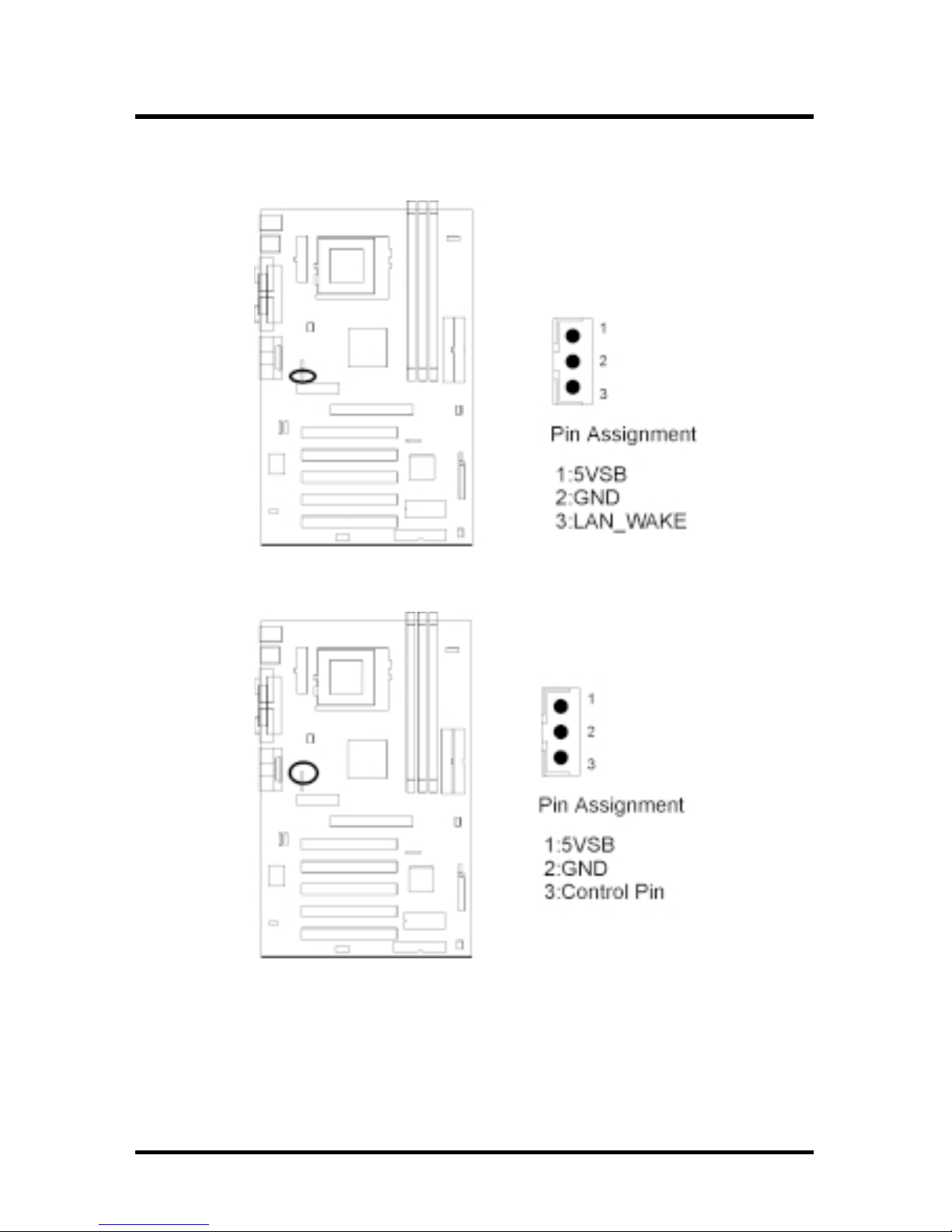
1.4.5Wake-ON-LAN header
1.4.6 Wake On Moden

9
Chapter 1 Quick Installation
1.4.7System temp. sensor header
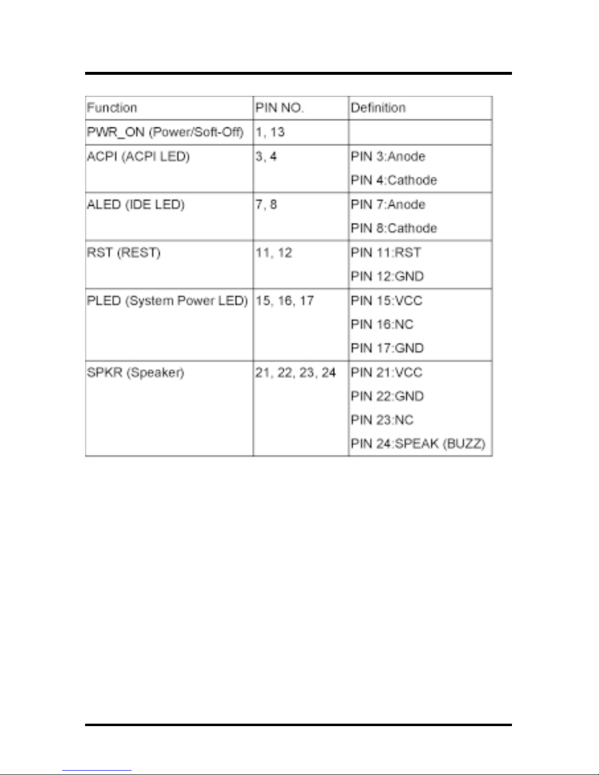
1.4.9Front panel connector (J43)
Chapter 1 Quick Installation
10

11
Chapter 1 Quick Installation
1.4.9 Aux-In connector(Aux_IN)
1.4.10 CD_In connector(CD_IN)

Chapter 1 Quick Installation
12
1.4.11 Internal USB connector
The motherboard has two USB ports onboard. The extra two
USB support can only functionable with the additional USB
riser kit.

13
Chapter 1 Quick Installation
1.4.12ATX power connector (J37)

Chapter 1 Quick Installation
14
1.5 Form Factor

15
Chapter 1 Quick Installation

16
Chapter 2 Feature
2 Features
2.1 Motherboard Components Placement

17
Chapter 2 Feature
[
.ONnoitpircseD
1rotcennocrewoPXTA
2X496AIV
3073tekcolSfoUPC
4stetkcolsMMID
5
srotcennocEDIht2dnaht1
6tolsRMA
7tolsPGA
8B686C28TVAIV
9rotcennocCDF
01draobnodnousroftespihcIMC
11stolsICP
21nIenohporciM,tuO/nIeniLidiM,kcitsyoJ
312MOC
41rotcennoclellaraP
511MOC
61stropBSU
71draobyeK/suoM2SP

18
Chapter 2 Feature
2.2 Block Diagram

19
Chapter 2 Feature
2.3 Specifications
Processor/Socket 370
Supports 1 processor through Socket 370
Supports 66M/100M/133MHz FSB (Front Side Bus)
Supports Intel Celeron (Mendochino,PPGA) CPU from 300A and higher
Supports Intel Celeron (Cu-128 FCPGA) CPU from 533A to 700MHz
and higher
Supports Intel Pentium III (Cu-256, FCPGA) CPU from 500 to 1GHz
and higher
Supports VIA Joshua CPU from 433 to 500MHz and higher
CPU Frequency Select
Supports S/W CPU speed adjustable (Jumper-free) method
Supports “Software assign ext. frequency” up to 166MHz
(by Bye Bye Jumper)
Supports “Software assign CPU Multiplier” from 2.5X to 12X
Memory
Supports PC66/PC100/PC133 SDRAM/VCM
Supports EDO,SDRAM,ESDRAM,VCM SDRAM
Supports Unbuffered/Registered DIMM
Supports 16M/64M/256M SDRAM Module
Maximum memory up to 1.5GB/768MB when using 256M/64M-16M
technology
Supports Suspend to Ram
Supports Singel-Sided/Double-sided DIMMs
Supports ECC memory module

20
Chapter 2 Feature
General I/O
PCI 2.2 compliance
Supports 32-bit/33MHz PCI interface
Supports A T A33/66/100 IDE interface
Supports Floppy interface
Supports 16550A UART interface
Supports ECP/EPP interface
Supports PS2 interface
Supports SIR interface
Supports USB interface
Sound support (VX133 only)
C-Media HW Sound controller on board
Supports Game/MIDI interface
Supports Win9X/WinNT/Win2K
Management
Supports Power on by LAN/Ext. Modem/Int. Modem /Alarm
Supports Resume by LAN/Ext. Modem/Int. Modem/Keyboard/PS2
Mouse/Alarm
Supports ACPI Blinking LED
Supports BIOS ROM Flash Control S/W protection
Supports STD,STR
Others
A TX Form Factor 305mm x 193mm

21
Chapter 2 Feature

22
Chapter 3 Hardware Setup
3 Hardware Setup
3.1 Before Installation
For installation, you may need some or all of the following tools:
Medium size flat blade screwdriver
Medium size Phillips head screwdriver
A 3/16 inch nut driver or wrench
ehterusneotsenilediugesehtwolloftsumsresU
.noitallatsnigniruddetcetorpsidraobrehtom
nevenehwffo-derewopsiretupmocruoyerusekaM.1
stnenopmocedisnihtiwnikrow
si,tnempiuqecinortcelerehtollaekil,draobrehtomehT.2
snoituacerpreporpehtekatesaelP.citatsotevitisnes
agnihcuotybflesruoydnuorg,elbissopfI.tignildnahnehw
evitcudnocstinidraobehtpeek.ksedroelbatlatem
nidellatsniebotydaerdnaderugifnocsitilitnugnipparw
.metsysruoy
yppolfdnadrahruoyhtobmorfyawastengamllapeeK.3
htobpeeK.srevirdwercscitengamyllaicepse,sevirdksid
.debmessasidfitrapasksiddrahdnayppolf
stidnaretupmocruoymorfyawasdiuqildnaretawpeeK.4
.stnenopmoc

23
Chapter 3 Hardware Setup
3.2 Install the Processor
tneverpottiotdehcattanafaevahdluohsUPCehT
nafaesahcrupneht,esacehttonsisihtfI.gnitaehrevo
.metsysruoynonrutuoyerofeb
ehtssorcanoitalucricriatneiciffussierehttahteruseB
ruoytahtgnikcehcylralugerybknistaehsrossecorp
eht,noitalucrictneiciffustuohtiW.gnikrowsinafUPC
ehthtobegamaddnataehrevodluocrossecorp
nallatsniyamuoY.draobrehtomehtdnarossecorp
.yrassecenfi,nafyrailixua

24
Chapter 3 Hardware Setup
Step1:
Locate the ZIF socket and open it by first pulling the lever of socket
upward.
Step2:
Insert the CPU into the socket. Please keep the lever right angle
when inserting CPU.

25
Chapter 3 Hardware Setup
Step3:
When inserting the CPU please note the correct orientation as
shown. The notched corner should point toward the end of the
lever.
Step4:
Push the lever down to close the socket.

26
Chapter 3 Hardware Setup
Step 5:
Attach the heatsink onto the CPU.
Step6:
Push the clip of heatsink downward to hock the ear of socket firmly.
Step7:
Finally, attach the fan cable to the CPU fan header FCPU.

27
Chapter 3 Hardware Setup
3.3 Install Memory Modules
The motherboard has three Dual Inline Memory Module (DIMM)
sockets and supports the maximum memory size up to 1.5GB.
These DIMM sockets only support 3.3V unbuffered SDRAM
modules. The motherboard also support SPD (Serial Presence
Detect) architecture to provide the best choice for performance vs.
stability.
Step 1:Open latches of DIMM socket
Step 2:Proofread the RAM module to the DIMM Socket.

28
Chapter 3 Hardware Setup
Step 3:Insert the RAM module into the DIMM socket.
Step 4:Press the latches into the notches of the RAM module.

29
Chapter 3 Hardware Setup
3.5 ATX Power Supply Connector
3.5.1Power on procedures
PETSnoitpircseD
1
esacmetsysehtesolc,edamerasnoitcennocllaretfA
.revo
2.ffoerasehctiwsllatahteruseB
3
detacolylpppusrewopehtotnidrocrewopehttcennoC
.esacmetsysruoyfokcabehtno
4
deppiuqesitahtteltuorewopadraocrewopehttcennoC
.rotcetorpegrusahtiw
5
aybV022/V011troppusylppusrewopehtfoynaM
tcerrocehtotylppusrewopruoyhctiwS.gnitteshctiws
.egatlovylppus
6
redrogniwollofehtnimetsysruoynonruT
rotinomehT.a
.secivedlanretxeehT.b
.metsysretupmocehT.c

30
Chapter 3 Hardware Setup
lliwsissahcehtfolenaptnorfehtnoDELrewopehT
-rewopnurnehtlliwmetsyseht,sdnoceswefretfA.thgil
ehtnoraeppalliwsegassemlanoitiddaemoS.stsetno
nihtiwgnihtynaeestonoduoyfI.tsetehtgnirudneercs
eht,rewopehtnonrutuoyemitehtmorfsdnoces03
ehtkcehceR.tsetno-rewopadeliafevahyammetsys
rofreliaterruoyllacrosnoitcennocdnasgnittesrepmuj
.ecnatsissa
3.5.2Power off procedures
PETSnoitpircseD
1.snoitacilppaerawtfosehtllamorftixE
2.metsysgnitareporuoynwodtuhs
3
eht,89/59niWgnisuerauoyfI.nottubrewopffohctiwS
retfayllacitamotuaffonrutdluohsylppusrewop
.nwodtuhsswodniW
4.secivedlanretxellaffonruT
5.rotinomruoyffonruT

31
Chapter 3 Hardware Setup
3.6 Back Panel
noitcnuF roloc noitpircseD
-suoM/2SP
e
neerG
troppusotdesuebnacrotcennocsihT
esuom2/SPa
/2SP
draobyek
elpruP
troppusotdesuebnacrotcennocsihT
.draobyek2/SPa
lasrevinU
suBlaireS
kcalB
,stropBSUowtsahdraobrehtomsihT
slarehpirepelbitapmoc-BSUyna
otnidetcennocebnacbuhro/dna
.tropBSUrehtie
troplaireS
&1MOC
2MOC
laeT
medomarofydaersitroplairesowT
.secivedlairesrehtoro
lelleraP
trop
ydnugruB
ro,sretnirprofdesusirotcennocsihT
.secivedlellaraprehto
,kcitsyoJ
dnaidiM
troPoiduA
dloG
emagroskcitsyojtcennocyamuoY
gniyalprofrotcennocsihtotsdap
rofsecivedIDIMtcennocro,semag
.oidualanoisseforpgnitide/gniyalp
ebnac)rolocemiL(tuOeniL
derewoprosenohpdaehotdetcennoc
)roloceulBthgiL(nIeniL.srekaeps
dedrocerebotsecruosoiduaswolla
hguorhtdeyalproretupmocruoyyb
kniP(ciM.rotcennoctuOeniLeht
ebotsenohporcimswolla)roloc
.eciovgnittupnirofdetcennoc

32
Chapter 3 Hardware Setup
-otuaebnacdraobyek2/SPdnaesuom2/SPehT
gulpuoyfisnaemtahT.draobrehtomsihtybdetceted
nacllitsti,rotcennocesuomehtotnidraobyek2/SPeht
sitI.asrevecivdnaelbuortynatuohtiwkrow
erofebretupmocehtffonrutuoytahtdednemmocer
.esuomro/dnadraobyekgnitcennocsidrognitcennoc

33
Chapter 3 Hardware Setup

34
Chapter 4 BIOS Setup
4 BIOS Setup
4.1 PhoenixNet Introduction
PhoenixNet is a service that provides PC users with best-of-breed,
free, software services to support their PC hardware and software
and to turn their computer into a powerful tool for communication,
entertainment, education and business
4.1.1Internet Launch System
The PhoenixNet Internet Launch System (ILS) is a patentpending technology built into the firmware to enable online
PC users worldwide to communicate with PhoenixNet and to
receive the free PhoenixNet services. ILS resides safely
within ROM and is activated the first time a user launches a
PhoenixNet-enabled PC with a Windows 98 Operating
System.
4.1.2PhoenixNet Online Services
When the PhoenixNet ILS detects an Internet connection, it
makes contact with the PhoenixNet server and delivers userselectable services from PhoenixNet’s Internet Partners.
These services are delivered to the user as hotlinks on the
desktop and in the web browser or, as applications that
PhoenixNet automatically packages, downloads and
installs.

35
Chapter 4 BIOS Setup
4.1.3PhoenixNet Online Services
selifruoydnaretupmocruoytcetorp&eganaM
moc.pleHyawevirDmoc.surivitnA
lootnoitacinummocaotniretupmocruoynruT
erahSevitcAebodAklaTeriFklaTtekcoR
retnectnemniatretnenaotniretupmocruoynruT
oidaRteNxoBekuJlaeR
enilnognippohsnehwyenomdnaemitevaS
moc.TENCnomiSyM
beWehtfotseB¡K
LOA:sPSIoohaYeticxEpanSsocyL:slatroP

36
Chapter 4 BIOS Setup
4.1.4User Boot
1
cihpargmorfnoitamrofnimetsyssdaerresU
.neercShcnuaL
2
SMsetelpmocdnaswodniWSMsretsigerresU
.EBOO
3.ecivresteNxineohPstcejeR/stpeccaresU
4.yrentrapPSIteNxineohPstcejeR/stpeccaresU
5.potksednoraeppanociPSIdnateNxineohP
4.1.5Internet Access
1.stluafedresworb&snocipotksedstesteNxineohP
2
otgniknilsraeppawodniwresworbweN
moc.tenxineohp.www .
3
&erawtfosrentraptenxineohPstcelesresU
.secivres
4yrtnuocdnaliam-e,emansretneresU
5
rentrapdetcelessllatsnidnasdaolnwodteNxineohP
.kcilc-esuomenohtiw,dnuorgkcabehtnierawtfos
6.liam-eybdraweryratenomseviecerresU
7
otsecivresteNxineohPgniognoseviecerresU
.ecneirepxetenretnIdnaCPriehtecnahne

37
Chapter 4 BIOS Setup
4.2 BIOS Setup
4.2.1Upgrade BIOS
The BIOS can be upgraded from a diskette with the Award
Flash utility — AWDFLASH.EXE. The BIOS image file, and
update utility are available from IWILL’s WEB site: www.
iwill.net
4.2.2Enter BIOS setup program
Power-on the system by either pressing the Power-On
button, or by using any of the power-on features provided by
the motherboard. Then, press the <Del> key after the
Power-On Self Test (POST), and before the scanning of IDE
devices. Simply look for the message “Press DEL to enter
SETUP” displayed at the bottom of the screen during the
boot up process. If the message disappears before you’ve
had a chance to respond, you can restart the system by
Turning off the system power then turn it on again, or
Pressing the “RESET” button on the system case, or
Pressing <Ctrl>, <Alt> and <Del> keys simultaneously.
ylluferacneebevahsgnittestluafedSOIBeht,yllareneG
ehtedivorpotrerutcafunammetsysehtybnesohc
yrevsitI.ytilibailerdnaecnamrofrepmumixametulosba
lluftuohtiwgnittesynaegnahcotsuoregnad
.uoytahtdnemmocerylgnortseW.gnidnatsrednu
.yltcefrepskrowmetsysehtfiSOIBruoyetadpuTONOD
dnatsrednuyllufuoysselnugnittesynaegnahcTONOD
.snaemtitahw

38
Chapter 4 BIOS Setup
4.2.3Using BIOS setup program
If the system is no longer able to boot after changing the settings,
the only way to recover it is to clear the data stored in RTC CMOS.
To reset the R TC CMOS data, take the JP1 jumper cap off pins 1-2,
place onto pins 2-3, and then place back onto pins 1-2 again. This
will return the RTC to the default setting. Then, get into the BIOS
setup program , choose Load Fail-Safe Defaults ; Load Optimized
Defaults, and select the original manufacturer default settings in
your CMOS.
Ç
Up Move to the previous field
È
Down Move to the next field
Å
Left
Move to the field on the left hand
side
Æ
Right
Move to the field on the right hand
side
<Esc>
Quit from setup program without
saving changes, or Exit from
current menu page and return to
main menu page
<PgUp> or
<+>
Select the previous value for a field
<PgDn> or <-> Select the next value for a field
<F1> General Help
<F2> Item Help
<F5> Previous Values
<F6> Fail-Safe Defaults
<F7> Optimized Defaults
<F10>
Save the current value and exit
setup program

39
Chapter 4 BIOS Setup
4.3 Main Menu
The main menu allows you to select from several setup pages. Use
the arrow keys to select among these pages and press <Enter> key
to enter the sub-menu. A brief description of each highlighted
selection appears at the bottom of the screen.

40
Chapter 4 BIOS Setup
4.4 Standard CMOS Features
4.4.1Date
This field specifies the current date. The date format is
<month>, <day>, and <year>.
4.4.2Time
This field specifies the current time. The time format is
<hour>, <minute>, and <second>. The time is calculated
based on the 24-hour (military-time) clock.

41
Chapter 4 BIOS Setup
4.4.3IDE Primary Master / Primary Slave /
Secondary Master / Secondary Slave
Press “Enter” to enter next page for detail hard drive setting.
4.4.3.1 IDE HDD Auto-Detection
Auto-Detect the HDDs Capacity, and its parameters,
ex: Cylinder, Head and Sector.
4.4.3.2 IDE Primary Master / Primary Slave / Secondary Master
/ Secondary Slave
This field specifies type of drive that corresponds to
the drive installed in your system. If you select User,
please specify the correct number of Cylinders,
Heads, and Sectors.
4.4.3.3 Capacity Auto Display your disk drive size
4.4.3.4 Access MODE
This field specifies the IDE translation mode.
launaM
gniniamerehttesuoystellaunagnitceleS
foepytehtstceleS.neercssihtnosdleif
.ksiddexif
otuA
)eluaVtluafeD(
rofseulavehtnisllifyllacitamotuaSOIB
.sdleifsrotcesdnasdaeh,srednilyceht
enoNdehcattaerasevirDksiDynA
LAMRON
gnisserddaSHClanoitidartseificepS
.edom
EGRALedomnoitalsnartSHCdednetxeseificepS
ABL.edomnoitalsnartABLseificepS
OTUA
)eluaVtluafeD(
dohtemnoitalsnartseificepsSOIB
.yllacitamotua

42
Chapter 4 BIOS Setup
enoN
)tluafedBevirD*(
detcennocsievirdyppolFynA
.ni52.5,K063
noitalsnartSHCdednetxeseificepS
edom
.ni52.5,M2.1detcennocsievirdyppolfM2.1A
.ni5.3,K027.detcennocsievirdyppolfK027A
.ni5.3,M44.1
)tluafedBevirD*(
detcennocsievirdyppolfM44.1A
.ni5.3,M88.2detcennocsievirdyppolfM88.2A
4.4.3.5 Cylinders
Set the number of cylinders for this hard disk.
4.4.3.6 Heads
Set the number of read/write heads
4.4.3.7 Precomp
Setting a value of 65535 means no hard disk
4.4.3.8 Sectors
Set the number of sectors per track
4.4.4Drive A / Drive B
This field specifies the traditional type of floppy drives.
4.4.5Floppy 3 Mode Support
3 Mode floppy drive is a type of 3.5-inch drive used by NEC
PC98 computers. It supports both 1.2M and 1.44M formats
using the same drive. This field specifies which drive
supports 3 Mode. When a floppy drive is specified to
support 3 Mode, the respective drive setting in “Drive A /
Drive B” field will be invalid.

43
Chapter 4 BIOS Setup
4.4.6Video
4.4.7Halt On
delbasiD
)eulaVtluafeD(
ddetcennocsievirdedoM3oN
AevirDAevirdsadetcennocsievirdedoM3A
BevirDBevirdsadetcennocsievirdedoM3A
htoBsevirdedoM3eraBevirddnaAevirdhtoB
AGV/AGE
)eulaVtluafeD(
dretpadaAGVroAGEseificepS
04AGC
nmuloc04htiwretpadaAGCseificepS
edom
08AGC
nmuloc08htiwretpadaAGCseificepS
edom
ONOMretpadaemorhconoMseificepS
srorrEllA
)eulaVtluafeD(
lataf-nonastcetedSOIBehtemithcaE
nayalpsiddnapotslliwmetsyseht,rorre
egassemrorre
srorrEoN
tahtsrorreynarofpotslliwmetsysehT
detcetedera
draobyeKtuB,llA
srorreynarofpotslliwmetsysehT
rorredraobyektpecxe
etteksiDtuB,llA
srorreynarofpotslliwmetsysehT
rorreetteksidtpecxe
yeK/ksiDtuB,llA
srorreynarofpotslliwmetsysehT
srorredraobyekdnaetteksidtpecxe

44
Chapter 4 BIOS Setup
4.4.8Base Memory
The POST (Power-On Self Test) determines the amount of
base (conventional) memory installed in the system. The
value of the base memory is typically 640K. This field has
no options.
4.4.9Extended Memory
The BIOS determines how much extended memory is
present during the POST. This is the amount of memory
located above 1MB in the processor’s memory address map.
This field has no options.
4.4.10Total Memory
Displays the total memory available in the system

45
Chapter 4 BIOS Setup
4.5 Advanced BIOS Features

46
Chapter 4 BIOS Setup
delbasiD,elbanE )eulaVtluafeD(
elbanE )eulaVtluafeD( delbasiD,
elbanE )eulaVtluafeD( delbasiD,
delbasiD,elbanE )eulaVtluafeD(
4.5.1Virus W arning
When this function is enabled, the BIOS monitor the boot
sector and partition table of the hard disk drive for any
attempt at modification. If an attempt is made, the BIOS will
halt the system and then display an error message.
Afterwards, if necessary, you can run an anti-virus program
to locate and remove the problem before any damage is
done.
Many disk diagnostic programs will attempt to access the
boot sector table, which can cause the above warning
message. If you run such a program, we recommend that
you first disable the Virus Warning function beforehand.
4.5.2CPU Internal Cache
This field configures the CPU internal cache (L1 cache).
4.5.3External Cache
This field configures the system’s external cache (L2 cache).
4.5.4CPU L2 Cache ECC Checking
This field specifies whether the CPU L2 cache supports ECC
or not.
4.5.5 Proccessor Number Feature
delbasiD,elbanE )eulaVtluafeD(

47
Chapter 4 BIOS Setup
elbanE )eulaVtluafeD( delbasiD,
4.5.6Quick Power On Self Test
This field allows the system to skip certain tests while
booting. This will decrease the time needed to boot the
system.
4.5.7First / Secondary / Third / Other Boot Device
The BIOS attempts to load the operating system from the
devices in the sequence selected in these items.
4.5.8Swap Floppy Drive
When enabled, floppy drives A and B will be exchanged
without the user physically changing the connection on the
cable.
4.5.10Boot Up Floppy Seek
Seeks disk drives during boot up. Disabling speeds boot up.
4.5.11Boot Up NumLock Status
This field determines the configuration of the numeric
keypad after system boot up. If On, the keypad uses
numbers keys. If Off, the keypad uses arrow keys.
,2-DDH,1-DDH,MORDC,ISCS,0-DDH,PIZ/SL,yppolF
delbasiD,001DIAR,NAL,3-DDH
delbasiD,elbanE )eulaVtluafeD(
elbanE )eulaVtluafeD( delbasiD,
NO ,)eulaVtluafeD( ffO

48
Chapter 4 BIOS Setup
4.5.12Gate A20 Option
This field configures how the gate A20 is handled. The gate
A20 is a device used to address memory above 1 MB. At
first, the gate A20 was handled from a pin on the keyboard.
While some keyboards still provide this support, it is more
common, and much faster, for modern system chipsets to
provide support for gate A20.
tsaF.cigolerocybdetroppuslangis02AetaG
lamroN
eluaVtluafeD( )
draobyekybdetroppuslangis02AetaG
.rellortnoc
4.5.13Typematic Rate Setting
This field determines if the typematic rate is to be used.
When enabled, the BIOS will report (after a moment) that the
key has been depressed repeatedly. When disabled, the
BIOS will report only once if a key is held down continuously.
This feature is used to accelerate cursor movements using
the arrow keys.
4.5.14Typematic Rate (Chars/Sec)
When Typematic Rate Setting enabled, this field specifies
how many characters will be displayed in one second when
a key is held down continuously.
delbasiD,elbanE )eulaVtluafeD(
6 )eulaVtluafeD( 03,42,02,51,21,01,8

49
Chapter 4 BIOS Setup
4.5.15Typematic Delay (Msec)
When enabled, typematic delay allows you to select the time
delay between when the key is first pressed and when the
acceleration begins.
4.5.16Security Option
This field configures how the system security is handled. It
works conjunction with SETTING SUPERVISOR / USER
PASSWORD page to control the security level of the system.
4.5.17OS Select for DRAM >64MB
When enabled, this field allows you to access the memory
that is over 64MB under OS/2.
4.5.18Report No FDD For WIN 95
For a floppy diskless system that runs Windows 95, this field
should be set to Yes.
cesm052 )eulaVtluafeD( cesm0001,cesm057,cesm005
2SO-noN,2SO )eulaVtluafeD(
puteS
)eulaVtluafeD(
SOIBretneotdrowssapasdeenmetsyS
margorpputes
metsyStoobotdrowssapasdeenmetsyS
ON,SEY )eulaVtluafeD(

50
Chapter 4 BIOS Setup
4.5.19Video BIOS Shadow
When enabled, the video BIOS will be copied to system
memory and increase the video speed.
4.5.20C8000-CBFFF/CC000-CFFFF/D0000-D3FFF
Shadow
D4000-D7FFF/D8000-DBFFF/DC000-DFFFF
Shadow
delbasiD,elbanE )eulaVtluafeD(
elbanE )eulaVtluafeD( delbasiD,

51
Chapter 4 BIOS Setup
4.6 Advanced Chipset Features
This setup page is used to specify advanced features available
through the chipset. The default settings have been chosen
carefully for most operating conditions. DO NOT change the value
of any field in this setup page without full understanding.

52
Chapter 4 BIOS Setup
DRAM Settings
The first chipset settings deal with CPU access to dynamic
random access memory (DRAM). The default timings have
been carefully chosen and should only be altered if data is
being lost. Such a scenario might well occur if your system
had mixed speed DRAM chips installed. Longer delays might
result, however this preserves the integrity of the data held in
the slower memory chips.
4.6.1SDRAM Cycle Length
When synchronous DRAM is installed, the number of clock
cycles of CAS latency depends on the DRAM timing. Do not
reset this field from the default value specified by the system
designer.
4.6.2Bank Interleave
Select numbers of Bank to Bank to realize fast and
seamless data access mode amony many different pages.
(DPSyB eluaVtluafeD sknaB4,sknaB2,)
4.6.3DRAM Clock
This field allows you to select the DRAM operating frequency
to get better performance.
klCtsoH
)eulaVtluafeD(
tnorFsadeepsemasehtsikcolcMARD
suBediS
zHM33-KLCH
ehtnahtsselzHM33tessikcolcMARD
suBediStnorF
zHM33+KLCH
ehtnahteromzHM33tessikcolcMARD
suBediStnorF
3,2 )eulaVtluafeD(

53
Chapter 4 BIOS Setup
4.6.4 Memory Hole
In order to improve performance, certain space in memory is
reserved for ISA cards. This memory must be mapped into
the memory space below 16MB.
delbasiD,M61-M51 )eulaVtluafeD(
4.6.5PCI Dynamic Bursting
When enabled, every write transaction goes to the write
buffer, and burstable transactions will then burst on the PCI
bus, and non-burstable transactions won’t burst on the PCI
bus.
When disabled, if the write transaction is a burst transaction,
the information goes into the write buffer and burst transfers
are later performed on the PCI bus. If the transaction is not
a burst transaction, PCI write occurs immediately (after a
write buffer flush).
elbanE )eulaVtluafeD( delbasiD,
4.6.6Delayed Transaction
The chipset has embedded 32-bit posted writer buffer to
support delayed transaction cycles. When enable, the
system is compliant with PCI specificationversion 2.2.
elbanE )eulaVtluafeD( delbasiD,
4.6.7System BIOS Cacheable
When enable accesses to the system BIOS will be cached
elbanE )eulaVtluafeD( delbasiD,
4.6.8 Video RAM Cacheable
When enabled, access to the video memory located at
A0000H to BFFFFH will be cached.

54
Chapter 4 BIOS Setup
elbanE )eulaVtluafeD( delbasiD,
4.6.10 AGP Aperture Size
This field specifies the size of system memory that can be
used for AGP graphics aperture.
M46,M23,M61,M8,M4 )eulaVtluafeD( M821,
4.6.11AGP-4X Mode
This item allows you to enable/disable the AGP-4X Mode.
elbanE )eulaVtluafeD( delbasiD,
4.6.12AGP Fast Writer
delbasiD,elbanE )eulaVtluafeD(
4.6.13OnChip USB Port
This should be enabled if your system have USB ports
external/internal on the system board and you wish to use it.
Even when so equipped, if you add a higher performance
controller, you will need to disable this feature.
delbasiD,delbanE )eulaVtluafeD(
4.6.14USB Keyboard Under DOS
Select Enabled if your system contains a Universal Serial
Bus (USB) controller and you have a USB keyboard under
DOS.
delbasiD,delbanE )eulaVtluafeD(

55
Chapter 4 BIOS Setup
4.7 Integrated Peripherals

56
Chapter 4 BIOS Setup
4.7.1 On-Chip Primary IDE Channel 0
This field enables or disables the onboard IDE controller.
elbanE )eulaVtluafeD( delbasiD,
4.7.2On-Chip Secondary IDE Channel 1
This field enables or disables the onboard IDE controller.
elbanE )eulaVtluafeD( delbasiD,
4.7.3Primary Master / Slave PIO
Secondary Master / Slave PIO
These fields configure the PIO (Programmable Input Output)
transfer mode for each IDE devices. The maximum transfer
rates of each PIO mode are listing as follow:
0edoMOIP
1edoMOIP
2edoMOIP
3edoMOIP
4edoMOIP
ces/BM3.3
ces/BM2.5
ces/BM3.8
ces/BM11
ces/BM6.61
otuA
)eulaVtluafeD(
0edoM
1edoM
2edoM
3edoM
4edoM
yllacitamotuaecivedhtiwdetaitogeN
ecivedsseccaotgnimit0edoMesU
ecivedsseccaotgnimit1edoMesU
ecivedsseccaotgnimit2edoMesU
ecivedsseccaotgnimit3edoMesU
ecivedsseccaotgnimit4edoMesU

57
Chapter 4 BIOS Setup
4.7.4Primary Master / Slave UDMA
Secondary Master / Slave UDMA
If you select Auto, the IDE controller uses Ultra DMA 33/66
Mode to access Ultra DMA-capable IDE devices.
otuA,delbasiD )eulaVtluafeD(
4.7.5Init Display First
This item allows you to decide which slot to activate first,
either PCI slot or AGP slot.
PGA,tolSICP )eulaVtluafeD(
4.7.6AC97 Audio
This item allows you to decide to enable/disable theVIA
chipset family to support AC97 Audio.
retnEsserP,otuA
4.7.6.1 Onboard Sound blaster
This item allows you to decide onboard legacy sound
blaster compatible device.
delbasiD,elbanE )eulaVtluafeD(
4.7.6.2 SB I/O Address Use
This item allows you to select sound blaster I/O
address.
H022 )eulaVtluafeD( H082,H062,H042,
4.7.6.3 SB IRQ Use Select
This item allows you to select sound blaster IRQ.
5QRI )eulaVtluafeD( 01.9,7,

58
Chapter 4 BIOS Setup
4.7.6.4 SB DMA Use Select
This item allows you to selec sound blaster DMA
channel.
0AMD , 1 )eulaVtluafeD( 3,2,
4.7.6.5 MIDI Port
This item allows you to selec MIDI Port enable/
disable.
delbasiD,elbanE )eulaVtluafeD(
4.7.6.6 MIDI Address Port
This item allows you to selec MIDI Port I/O address.
,H323-023,H313-013,H303-033
H333-033 )eulaVtluafeD(
4.7.6.7 Game port Address
This item allows you to select game port enable/
disable.
delbasiD,H702-002 )eulaVtluafeD(
4.7.7AC97 Modem
This item allows you to decide to enable/disable the VIA
chipset family to support AC97 Modem.
otuAdelbasiD, )eulaVtluafeD(
4.7.8IDE HDD Block Mode
When enabled, the IDE controller will use the faster block
mode to access devices.
elbanE )eulaVtluafeD( delbasiD,

59
Chapter 4 BIOS Setup
4.7.9Onboard FDC Controller
This field enables or disables the onboard floppy controller.
elbanE )eulaVtluafeD( delbasiD,
4.7.10Onboard Serial Port 1 / 2
These fields configure the onboard serial ports. There are
several port addresses and IRQ channels to select from.
4QRI/8F3
)eluaVtluafeD(
4QRI,h8F3sserddatroP
3QRI/8F23QRI,h8F2sserddatroP
4QRI/8E34QRI,h8E3sserddatroP
3QRI/8E23QRI,h8E2sserddatroP
otuAQRIdnasserddatropsngissaSOIB
.yllacitamotualennahc
.delbasiDtroplairesselbasiD
4.7.11 COM2 Mode Select
A second serial port is using a serial port bracket connected
from the motherboard to an expansion slot opening.
dradnatS ,)eulaVtluafeD( RIKSA,RISPH
4.7.1 1.1RxD, TxD Active
When setting the field to either IrDA or ASKIR, you
must select the active level of receiving and
transmission signal.
oL,iH )eulaVtluafeD( iH,iH/oL,oL/iH,oL/

60
Chapter 4 BIOS Setup
4.7.1 1.2IR Duplex Mode
When setting the field to either HPSIR or ASKIR,
you must select the mode of receiving and
transmitting signals.
flaH )eulaVtluafeD( lluF,
4.7.12 Onboard Parallel Port
This field configures the onboard parallel port. There are
several port addresses and IRQ channels to select from.
7QRI/873
)eulaVtluafeD(
7QRI,h873sserddatroP
5QRI/8725QRI,h872sserddatroP
7QRI/CB37QRI,hCB3sserddatroP
delbasiD
troplellarapselbasiD
4.7.13Parallel Port Mode
This field configures the operating mode of an onboard
parallel port. Ensure you know the specifications of your
parallel port devices before selecting field.
lamroN )eulaVtluafeD( PPE+PCE,PCE,PPE,
4.7.14ECP Mode Use DMA
When the Parallel Port Mode field is configured as ECP, it
needs a DMA channel for data transfer. This field specifies
the DMA channel for ECP parallel port use.
11lennahcAMDesU
3 )eulaVtluafeD( 1lennahcAMDesU

61
Chapter 4 BIOS Setup
4.7.15EPP Mode Select
When the Parallel Port Mode field is configured as EPP,
ECP+EPP mode, the EPP version needs to be specified.
Please refer to ypur peripheral document before selecting
field.
7.1PPElocotorp7.1PPEesU
9.1PPE
)eulaVtluafeD(
locotorp9.1PPEesU

62
Chapter 4 BIOS Setup
4.8 Power Management Setup
Each power-saving mode has a respective timer. The value of the
timer can be assigned or reloaded and it will count down to zero.
When the timer equals to zero, the system will be forced into the
related suspend or power-saving mode. If any predefined signal or
event is detected during the timer counting period, the timer restarts
automatically.

63
Chapter 4 BIOS Setup
4.8.1Power Management
This feature allows the user to select the default parameters
for the power-saving mode.
gnivasniM
metsyseht,ruohenorofeldinehW
.edomdnepsusretne
gnivaSxaM
eht,setunimneetfifrofeldinehW
.edomdnepsussretnemetsys
enifeDresU
)eluaVtluafeD(
metsysehtemitehtyficepsnacresU
.edomdnepsussretne
4.8.1.1 APM HDD Power Down Timer
This field specifies the time the system enters HDD
power down. It is available only when the Power
Management field is set to User Define.
,niM9,niM8,niM7,niM6,niM5,niM4,niM3,niM2,niM1
,niM51,niM41,niM31,niM21,niM11,niM01
elbasiD )eulaVtluafeD(
4.8.1.2 APM Doze Timer Mode
This field specifies the timer value of Doze Mode. It
is available only when the Power Management field
set to User Define.
,ruoH1,niM03,niM02,niM01niM8,niM6,niM4,niM2,niM1
elbasiD )eulaVtluafeD(
4.8.1.3 APM Suspend Timer
This field specifies the time the system enters powersaving mode. It is available only when the Power
Management field is set to User Define.
,niM04,niM03,niM02,niM01niM8,niM6,niM4,niM2,niM1
elbasiD,ruoH1 )eulaVtluafeD(

64
Chapter 4 BIOS Setup
4.8.2ACPI Suspend T y pe
There are several ACPI modes used to save computer’s
energy.
)SOP(1S
)eluaVtluafeD(
UPCeht,etatS-nO-rewoPehtsisihT
metsyseht,deepsrewolstasnurkcolc
.deepsrewolstasetarepo
)RTS(3S
lla,etatSmaR-oT-dnepsuSehtsisihT
smetsysnidevaseblliwatadmetsys
ehttpecxesecivedlladnayromem
.ffotuhslliwyromem
nac,dracAGVruoygnikcehcesaelP(
).edom3Sehttroppus
4.8.3PM Control by APM
When enabled, an Advanced Power Management (APM)
protocol will be activated to handle the power-saving mode.
seY,ON )eulaVtluafeD(
4.8.4Video off Option
This field specifies the method that video subsystem used for
power saving.
NOsyawlA
rewopgnirudnoniamerlliwrotinoM
.sedomgnivas
ffOdnepsuS
smetsysehtnehwdeknalbrotinoM
sedomdnepsuSehtsretne
ffOsedoMllAmetsysehtnehwdeknalbrotinoM
.edomgnivasrewopynasretne

65
Chapter 4 BIOS Setup
4.8.5Video off Method
knalB+CNYSH/V
)eluaVtluafeD(
latnozirohdnalacitrevehtffonruT
sknalbetirwdnastropnoitazinorhcnys
.reffuboedivehtot
neercSknalB
reffuboedivehtotsknalbsetirW
.eylno
SMPD
tnemeganamrewopyalpsidlaitinI
.SMPDhtiwgnilangis
4.8.6MODEM Use IRQ
This determines the IRQ in which the Modem can use.
3 ,)eulaVtluafeD( AN,11,9,7,5,4
4.8.7PWR-Off Mode by PWR-BTTN
This field specifies the function of power button.
ffO-tnatsnI
)eluaVtluafeD(
metsyseht,desserpnottubrewopnehW
yletaidemmiffosnrut
.ceS4yaleD
desserpneebsahnottubrewopehtretfA
metsyseht,sdnocesruofrofdlehdna
ffosnrut

66
Chapter 4 BIOS Setup
4.8.8Wake Up Events
These are I/O events whose occurrence can prevent the
system from entering a power-saving mode, or can awaken
the system from such a mode. In effect, the system remains
alert for anything that occurs to a device configured and
recognized by the system, even when the system is in a
power down mode.
4.8.8.1 VGA
When ON, your can set the VGA to awaken the
system.
FFO )eulaVtluafeD( NO,
4.8.8.2 LPT & COM
When On, any activity from one of the listed system
peripheral devices or IRQs wakes up the system.
MOC/TPL )eulaVtluafeD( enoN,TPL,MOC,
4.8.8.3 HDD & FDD
When On, any activity from either hard disk drive or
floppy disk drive wakes up the system.
NO )eulaVtluafeD( FFO,
4.8.8.4 PCI master
When On, the system can be resumed from power
saving mode by any PCI / master activity signal.
FFO )eulaVtluafeD( NO,
4.8.8.5 Wake up by PCI card
When enabled, you can “wake-up” your system
using a PCI rev.2.2 card, such as a WOL card,
connected in your PCI slot.
delbasiD,delbanE )eulaVtluafeD(

67
Chapter 4 BIOS Setup
4.8.8.6 Wake Up by Ring/LAN
When enabled, the PC can power-on through an
external modem connected to your PC. For
example, you may send an e-mail message to your
PC from another location, and this will power-on your
PC. When using this feature, you must have a
modem, and your PC must be turned off.
delbasiD,delbanE )tluafeD(
4.8.8.7 PWROn/Resume by Alarm
When enabled, you can set the date and time to
automatically power-on your PC (similar to an alarm
clock). The alarm from RTC (real-time clock)
automatically turns on the system.
delbanE,nim,rh(remiTdna)13-0(etaDsteS
sietadnehW.CPehtno-rewopot)ces
.yadyreveroftessiremiTeht,0ottes
delbasiD
)eluaVtluafeD(
noitcnufmralaCTRselbasiD
4.8.8.8 Primary INTR
tluafeD,FFO,NO )eluaVtluafeD(
4.8.8.9Primar INTR
delbasiD,FFO,NO )eulaVtluafeD(

68
Chapter 4 BIOS Setup
4.8.8.10IRQs Activity Monitoring
When On, any event that occurs will awaken the
system after it has powered-down.The following is a
list of IRQs, or Interrupt Requests, which can be
exempted much as the COM ports and LPT ports
above can. When an I/O device wants to gain the
attention of the operating system, it signals this by
causing an IRQ to occur. When the operating
system is ready to respond to the request, it
interrupts itself and performs the service.

69
Chapter 4 BIOS Setup
4.9 PnP/ PCI Configurations

70
Chapter 4 BIOS Setup
4.9.1PNP OS Installed
The field specifies whether a Plug and Play operating system
is installed.
ON,seY )eulaVtluafeD(
4.9.2Reset Configuration Data
Normally, you leave this field Disabled. Select Enabled to
reset Extended System Configuration Data (ESCD) when
you exit Setup if you have installed a new add-on and the
system reconfiguration has caused such a serious conflict
that the operating system can not boot.
delbasiD,elbanE )eulaVtluafeD(
4.9.3Resources Controlled By
The Award Plug and Play BIOS has the capacity to
automatically configure all of the boot and Plug and Play
compatible devices. However, this capability means absolutely nothing unless you are using a Plug and Play operating
system such as WindowsÒ98/95/NT. If you set this field to
“manual” choose specific resources by going into each of
the sub menu that follows this field (a sub menu is preceded
by a “Ø”).
launaM.resuehtybdellortnocsecruoseR
)DCSE(otuA
)eluaVtluafeD(
SOIBybdellortnocsecruoseR
.yllacitamotua
4.9.3.1 IRQ Resources
When resources are controlled manually, assign
each system interrupt a type, depending on the type
of device using the interrupt.

71
Chapter 4 BIOS Setup
4.9.3.1.1IRQ3/4/5/7/9/10/1 1/12/14/15 assigned to
devreseReciveDICP )eulaVtluafeD(
4.9.4PCI / VGA Palette Snoop
This field controls the ability of a primary PCI graphics
controller to share a common palette with an ISA/VESA video
or MPEG card.
delbanEdracGEPMASIhtiwskrow-ocAGVICP
delbasiD
)eluaVtluafeD(
.evobatpecxesesacllA
4.9.4.1-5 PCI 1 IRQ
PCI 2/5 IRQ
PCI 3 Onboard Sound IRQ
PCI 4/PCI5 RAID IRQ
These fields set how IRQ use is determined for each
PCI slot. The default setting for each field is Auto,
which uses auto-routing to determine IRQ use.
otuA )eulaVtluafeD( 51,41,21,11,01,9,7,5,4,3

72
Chapter 4 BIOS Setup
4.10 PC Health Status
This page is monitoring your status of computer. On the screen
displays CPU/System temperature, F AN speed, and voltages.

73
Chapter 4 BIOS Setup
4.1 1 Iwill Smart Setting
74
Chapter 4 BIOS Setup
CPU FREQUENCY SETUP
In general, when adjusting the CPU frequency, you should select a
matched bus frequency for both the CPU and the motherboard.
The reason is that your CPU can only communicate with its external
components at the same speed at which the components operate.
In other words, if your motherboard bus speed is 100 MHz, you
should start by selecting 100 MHz (as a “base”) to set the CPU
frequency. This frequency is also referred to as the “system bus
frequency” or external frequency.
To understand how does CPU works, and how does it related to
FSB and multiplier, here is the example:
CPU speed = FSB x Multiplier (CPU Ratio)
800Mhz = 100Mhz x 8
4.1 1.1Spread Spectrum
This item configures radiation emitted from the system.
When enabled, system will release less radiation.
delbasiD,delbanE )eulaVtluafeD(
evahtsumsresU.deetnaraugtonsignikcolc-revO
otevitalerUPCreporpfoegdelwonklaitnatsbus
enodebdluohsgnikcolc-revO.sdeepsUPCgnitsujda
.stsettcudnocohwsreenignedecneirepxeybylno

75
Chapter 4 BIOS Setup
4.1 1.2CPU/PCI Clock
This field allows user to adjust the CPU external and to show
the PCI clock.
zHM33/66
zHM43/86
zHM73/57
zHM04/08
zHM14/38
zHM03/09
zHM13/59
zHM331/001
zHM43/301
zHM53/501
zHM63/011
zHM73/211
zHM83/511
zHM13/421
zHM23/031
zHM33/331
zHM43/531
zHM43/831
zHM53/041
zHM63/441
zHM73/051
zHM83/551
zHM04/061
zHM14/661
4.1 1.3CPU Clock Ratio
8,5.7,7,5.6,6,5.5,5,5.4,4,5.3,3
21,5.11,01,5.9,9,5.8
Note:BIOS will auto-detect and display your CPU Ratio
4.11.4BIOS-ROM Flash Protect
hserF-noNSOIByB
elbahserFSOIByB
htiweratekramehtnidlossUPCehtfotsoM
ylnonacUPCeht,esacsihtnI.dekcolreilpitlum
ehtnevegnittesreilpitlumyrotcafs'titanoitcnuf
eyBeyBLLIWIehtnidegnahcsignittesreilpitlum
.rempuJ

76
Chapter 4 BIOS Setup
4.12 Load Fail Safe Defaults
When you press <Enter> on this item you get a confirmation dialog
box with a message similar to: Pressing ‘Y’ loads the BIOS default
values for the most stable, minimal-performance system operations.

77
Chapter 4 BIOS Setup
4.13 Load Optimized Defaults
When you press <Enter> on this item you get a confirmation dialog
box with a message similar to:

78
Chapter 4 BIOS Setup
4.14 Set Supervisor/ User Password Setting

79
Chapter 4 BIOS Setup
These setup pages are used for password setting. When a
password has been enabled and the Security Option field is set as
Setup, you will be required to enter the password every time you try
to enter BIOS Setup program. This prevents an unauthorized
person from changing any part of your system configuration.
Additionally, if the Security Option field is set as Boot, the BIOS will
request a password every time your system boot. This would
prevent unauthorized use of your computer.
In you wish to use this function, bring the cursor to this field, then
press <Enter>. The computer will display the message, “Enter
Password”. T ype your password and press <Enter>. After the
message onfirm Password” is displayed, re-type your password.
The Supervisor Password function will be in effect after you save
and exit setup.
To disable a password, bring the cursor to this field, then press
<Enter>. The computer will display the message, “Enter
Password”. Press <Enter>. A message will confirm that the
password is disabled. Once the password is disabled, the system
will boot and you can enter setup program freely.

80
Chapter 4 BIOS Setup
4.15 Save & Exit Setup
Saves current CMOS value and exit BIOS setup program.

81
Chapter 4 BIOS Setup
4.16 Exit Without Saving
Abandons all CMOS value changes and exits BIOS setup program.

82
Chapter 5 On board Audio
5 On board Audio (For VX133 Only)
The on board 4.1 channel PCI Audio on Iwill motherboards offer a
new generation PCI audio solution: it utilizes the state-of-the-art
CRL® 3D Audio technology (HRTF 3D positional audio), and
supports Microsoft® Direct Sound ® 3D and Aureal®’s A3D®
interfaces. Better yet, it supports two / four speakers and DLS
based (Down Loadable Sound) wave table music synthesizer which
supports the Direct Music®.
T rademark Acknowledgments
Microsoft, Windows, Direct Sound 3D, and Direct Music are
trademarks of Microsoft Corporation. Sound Blaster is a trademark
of Creative Technology, Ltd. Aureal is a trademark of Aureal Inc.
A3D is a registered trademark of Aureal Inc. All other trademarks
and registered trademarks mentioned in this manual are the
property of their respective holders and are hereby acknowledged.
Information in this manual is subject to change without notice.

83
Chapter 5 On board Audio
5.1 Audio Features
5.1.1Special Features
32 bit PCI bus master. Full duplex playback and recording,
built-in 16 bits CODEC.
HRTF 3D positional audio, supports both Direct Sound 3D®
& A3D® interfaces, supports earphones, two and four
channel speakers mode.
Support Windows 95/ 98/ 2000 and Windows NT 4.0.
MPU-401 Game/Midi port and legacy audio SB16 support.
Downloadable Wave Table Synthesizer, supports Direct
Music®.
5.1.2Stereo Mixer and FM Music Synthesizer
Stereo analog mixing from CD-Audio, Line-in
Stereo digital mixing from V oice, FM/W ave-table, Digital CD-
Audio
Mono mixing from MIC and software adjustable volume
OPL3 FM synthesizer (4 operators)
Up to 15 melody sounds and 5 rhythm sounds (20 voices)
5.1.3Game and Midi Interface
Fully compatible with MPU-401 Midi UART and Sound
Blaster Midi mode/ Standard IBM PC joystick/game port

84
Chapter 5 On board Audio
5.2 Driver Installation
5.2.1DOS Installation
Before beginning the installation, please make sure that your
hard disk has sufficient space(min. 4MB). Insert the Power
Installer CD into the CD-ROM Drive.
1PETSsrevirdSODoiduaICPotyrotceridegnahC
:epytdna,tpmorpSODtaredlof
]retnE[LLATSNI
2PETSottnawuoyhcihwhtapseitilituSODepyT
.llatsni
3PETShcihwhtapehtotelifehtdnapxelliwmargorP
.deificepsev'uoy
4PETS.srevirdlaitiniddalliwmargorpllatsnI
5.2.2Win 95/98 Installation
We recommend that you have Microsoft Windows intalled,
and remove any exsisting sound drivers from your current
system, before you install this PCI sound device driver

85
Chapter 5 On board Audio
1PETS,rekaeps,elbacoiduaehtllatsni,metsysruoyfforewoP
ehtotniDCrellatsnIrewoPlliwIehttresnidna,enohporcim
.evirdMOR-DC
2PETS59swodniWtfosorciMehtretnedna,retupmocehtnonruT
.0002/89/
3PETS:sihtekiltpmorpswodniwaeeslliwuoY
dnuoFerawdraHweN"
eciveDoiduAaidemitluMICP
ehtgnillatsnisidnaerawdrahwendnuofsahswodniW
"txeN"kcilC.nwohsxobgolaidehtneht,"tiroferawtfos
.noogotnottub
4PETS.htapsrevirdyficepsotnottub"snoitacoLrehtO"nokcilC
5PETSkcilc,dnuofeciveDoiduAICP)XS(xD3C/8378IMCnehW
hsiniF .
6PETSretfA,yllcitamoituasrevirdecivedgnillatsnisimetsys,woN
ehtsdulcninoitallatsniehthsiniflliwmetsyseht,elihwa
.srevirdecivedgniwollof
eciveDoiduAICP)XS(XD3C/8378IMC
eciveDkcitsyoJICP)XS(XD3C/8378IMC
eciveDycageLICP)XS(XD3C/8378IMC
7PETSkcilC trats yek
8PETStceleS nuR
9PETSnoitacilppaswodniWrofhtapdnaevirdehtniyeK
.margorpnoitallatsni
01PETSkcilC KO ehtwollofdna,erudecorpnoitallatsniehttratsot
ehtllanehW.noitallatsniehthsinifotsnoitcurtsnineercs-no
tuhsesaelp,dellatsnineebevahserawtfosnoitacilppa
ruoytooberdna,metsys0002/89/59swodniWnwod
.metsys

86
Chapter 5 On board Audio
5.2.3Win 95/98 Un-Installation
In the cases you are experiencing some technical difficulties
(the sound device is not function properly). It is suggested
that you proceed with the un-install procedure:
1PETSkcilC trats .nottub
2PETStceleS nur .meti
3PETSrednuksidrevirdniEXE.VRDTSNIUdniF
.redlofsrevird89/59niW
4PETS.tinuR
5PETSllatsni-erotsnoitcurtsnineercs-noehtwolloF
.erawdraheht
If you want to completely remove the drivers, you can also
run the un-install procedure as described previously, and
then reboot the system.
5.2.4Windows NT4.0 Installation
We recommend that you have Microsoft Windows NT
intalled, and remove any exsisting sound drivers from your
current system, before you install this PCI sound device
driver.

87
Chapter 5 On board Audio
1PETS"gnitteS"otrabthgilhgihehtevom,nottub"tratS"kcilC
."lenaPlortnoC"ehttcelesdna,meti
2PETS..noci"aidemitluM"kcilc-elbuoD
3PETS.nottub"ddA"sserpdna,egap"seciveD"tceleS
4PETSfotsiL"nimeti"revirDdetadpUrodetsilnU"tceleS
."srevirD
5PETS.nottub"KO"sserpdnameti"8378MCaideM-C"tceleS
6PETS.eulavO/IreporptceleS
7PETSnottub"KO"sserP
8PETSdeksagniebnehwmetsysehttratseR
9PETSretpadAoiduAICPehtdellatsniydaerlaevahuoy,woN
uoyfI.yllufsseccus0.4TNswodniWtfosorciMrednu
ehteunitnoc,snoitacilppaswodniWehtllatsniottnaw
:spetsgniwollof
01PETSyektratskcilC
11PETSmetinuRtceleS
21PETSnoitacilppaTNswodniWrofhtapdnaevirdniyek
,margorpnoitallatsni
31PETSwollofdna,erudecorpnoitallatsniehttratsotKOkcilC
nehW.noitallatsniehthsinifotsnoitcurtsnineercs-noeht
tuhsdellatsnineebevahserawtfosnoitacilppafolla
ruoytoobernehtdna,metsysTNswodniWehtnwod
.metsys

88
Chapter 5 On board Audio
5.3 The Audio Rack
5.3.1Introduction
By means of a user-friendly interface (as easy as operating
your home stereo system), this PCI audio rack provides you
with the control over your PC’s audio functions, including the
advantage of four speakers mode enable/ disable,

89
Chapter 5 On board Audio
5.3.2About Audio Rack
The Audio Rack is consisted of several major components.
5.3.2.1 Control Center
Controls the display of the PCI Audio Rack’s
components.
5.3.2.2 MIDI Player
Plays MIDI music files, and allows you to create your
personal song playlists, and play the song files.
5.3.2.3 MP3/W ave Player
Records and plays digital audio (mp3/wave) files.
Allows you to create wave file playlists, and playback
the wave files.
5.3.2.4 CD Player
Plays standard audio CDs. Allows you to create
your favorite song playlists.
5.3.2.5 System Mixer
Controls the volume level of your audio inputs and
outputs
5.3.3Showing or Hiding Audio Rack Components
To remove or add a component from the display, click on the
component’s button on the Control Center’s Button Bar or
toggle it off.
5.3.4MIDI Player, Wave Player, and CD Player
CD Player(above, similar to MP3/Wave Player and MIDI Player)

90
Chapter 5 On board Audio
5.3.4.1 Sel (or Trk) field:
If you have multiple selections in your playlist, this
shows the number of the current selection or CD
track.
5.3.4.2 Current File or Track:
The name of the current MIDI file, wave audio file, or
CD track.
5.3.4.3 Total Length field:
Displays the total length of files or tracks in minutes
and seconds.
5.3.4.4 Current Time field:
Displays the current time of files or tracks in minutes
and seconds when playback or recording.
5.3.5System Mixer
System Mixer allows you to control all the audio output and
input levels. System Mixer displays the volume controls which
your audio drivers make available. The names for these
controls may vary.
Mixer panel while the four speakers mode is enabled.
Mixer panel while the four speakers mode is disabled.
nottubliatederomroneercsplehehtotreferesaelP
.snoitpircsednoitcnuf
)reyalpehtnonottubplehnokcilc(

91
Chapter 5 On board Audio
5.3.5.1 Volume Control:
Clicking on this button shows and allows you to use
the output level controls.
5.3.5.2Recording Control:
Clicking on this button shows and allows you use the
input level controls.
5.3.5.3 Input and Output Level Sliders and Buttons:
For each input or output signal type, the control
slider controls the loudness whereas the horizontal
slider controls the balance between the two speakers.
The mute button temporarily stops input or output
without changing slider positions.
Control types and names might vary. The common
types are listed below:
a Vol:
The master control for all outputs. The strength of an
output signal is determined by both the V ol slider and
the slider for the individual output. To affect all
outputs, move the Vol slider. To change the output of
an individual output type, move its slider.
b Line-in/Rear:
Controls the audio hardware’s Line In or Line Out
levels. Line levels might be for an externally attached
cassette player, for instance, while the four speakers
mode is enabled, this control becomes the Rear
speaker volume control.
c Mic:
Controls the microphone input level.

92
Chapter 5 On board Audio
d Wave:
Controls wave (voice) playback or the recording
levels.
e FM:
Controls the FM music playback or the recording
level.
f Aux-in:
Controls the Aux-in music play or the recording level.
g PC-SPK:
Controls the external PC speaker input level.
h CD:
Controls the CD drive output level, for CD drives
configured to play their audio output through the PCs
audio hardware.
i 4SPK:
Turn on or turn off the Rear speakers effect.
j Surround:
Turn on or turn off the 3D surround sound effect.

93
Chapter 5 On board Audio
5.3.5.4 Mute Buttons:
Toggle between muting and enabling the signal. A
button with a lit LED is enabled, and when it is not lit,
it means it is mute. Several output signals can usually
be enabled at once.
5.3.6MP3 Player
MP3 player can play both wave files and MP3 files.
MP3 player while the loop function enables.

94
Chapter 5 On board Audio
5.3.7The 4 Speakers System
The on board audio on Iwill motherboards provide 2 wave
channels (front/rear + subwoffer), known as the 4.1
speakers system. When games or application programs via
DirectSound® 3D or A3D® interface locate the sound
sources to the listener’s back, the two rear speakers will
work to enhance the rear audio positional effect, so as to
complement the insufficiency of using only two front
speakers to emulate the audio effect. The following is the
hardware installation and the software setups:
5.3.7.1 The speaker installation.
Connect the front pair speakers to the Line-out jack
of the audio adapter, and then connect rear pair
speakers to Line-in/Rear jack of the audio adapter.
5.3.7.2The positions of the speakers
Put your speakers the way the following picture
suggests, to deliver the best audio result.

95
Chapter 5 On board Audio
5.3.7.3 The mixer setup
There is a 4 speakers option in the volume control of
the mixer, and when you enable this option, it means
the rear speakers are connected to Line-in/Rear
jack.
When Line-in/Rear jack is connected to other
external Line-in sources, please DO NOT enable this
option in order to avoid hardware conflicts.
Regarding rear speaker option, you can turn on or
turn off the output of the back speakers, and adjust
the volume, to have the rear/front speakers have the
same volume.
5.3.7.4 The demo
Execute the Helicopter demo within the C3D HRTF
Positional Audio Demos of this audio adapter. When
the helicopter flies behind you, the rear speakers will
work.

96
Chapter 6 Power Installer CD
6 Power Installer CD
6.1 Software Installation
The attached Power Installer CD contains all the necessary drivers,
utilities. It provides an easy way for users to install the needed
drivers without going through a complicated process. The Power
Installer CD is able to auto-detect and display the drivers, utilities
needed for your motherboard.
6.1.1What’s inside Power Installer CD for this
motherboard
revirD
revirDkcaPecivreS
revirDoiduAdraobnO
orPerotSXtnioPhgiH
eliFhctaPdrawA
launaMs'resU
ytilitUerawtfoS
suriV-itnAnilliC-CP
ytilitUrotinoMerawdraH
ediuGksiDoTdnepsuS
redaeRtaborcAebodA
ytilitUnoitacilppAoiduA
)ylnoTN/89swodniWroF(
revirDekaM
tixE

97
Chapter 6 Power Installer CD
6.2 How to use the Power installer CD
The Power Installer CD supports the Auto Run program under
Windows 98/95/2000 and Windows NT operating systems. All the
necessary drivers, utilities and manual for this motherboard will
show on the screen.
Power Installer does not support a keyboard at this moment.
You must use a mouse to install it.
6.2.1How to view manual
This Power Installer CD includes detailed information of all
manuals for every motherboard manufactured. Please insert
the Power Installer CD into the CD-ROM drive; Click the
“View Manual” item, and select the product that you want to
view.
6.3 How to make driver diskette
6.3.1Without O.S. installed
This bootable Power Installer CD also allows you to boot up
your system, even when the OS has not been installed.
During the boot-up process, you can perform Diskette
Creator, which will automatically make the driver diskettes
you need. Follow the instructions below to make your own
device driver floppy diskettes if you have a CD-ROM with
IDE interface. If you have already installed SCSI CD-OM,
please make sure your SCSI host adapter supports bootable
CD-ROM, and then proceed directly to step 8 ,and then
finish the procedure.

98
Chapter 6 Power Installer CD
1PETSrono-rewop,tsriF toob .metsysruoy
2PETS
<sserP leD retneotecneuqestoobgnirudyek>
ytilitUputeSSOMC .
3PETS
tcelesotsyekworraesU SOIBDECNAVDA
SERUTAEF sserpneht,unemehtno etnE .r
4PETS
tceleS eciveDtooBtsriF tluafedehtegnahcdna
otgnittes MORDC nwoDegaP/pUegaPgnisu
.yek
5PETS
<sserP csE PUTESSOMCotkcabogotyek>
.unemytilitU
6PETS<sserP 01F .puteStixEdnaevaStcelesot>
7PETS
sserP Y elbaerauoywoN.etelpmocotretnEneht
.MOR-DCehtmorfmetsysehtputoobot
8PETS
MOR-DCehtotniDCrellatsnIrewoPehttresnI
.retupmocehttrats-erdnaevird
9PETS
yllacitamotuaetucexewonlliwrotaerCetteksiDehT
.seteksidrevirdnworuoygnikamrof
01PETS
ehtotgnidroccasetteksidrevirdderisedehtekaM
.neercsnodeyalpsidsnoitcurtsni
6.3.2Under windows 98/95/NT
You may just click on the software Make Driver Diskettes
Utility shown on screen, then select the driver you need,
follow the messages shown on screen to complete.

99
Chapter 6 Power Installer CD
6.4 Install driver
6.4.1How to install Service Pack Driver
You may just click on the Service Pack Driver shown on
screen that needs to be installed, then follow the prompts to
complete setup.
6.4.2How to install Onboard Audio Driver File
You may just click on the Onboard Audio Driver shown on
screen that needs to be installed, then follow the prompts to
complete setup.
6.4.3How to Install High Point XStore Driver
You may just click on the High Point XStore Driver shown
on screen that needs to be installed, then follow the prompts
to complete setup.
6.4.4How to install Award Patch Driver
You may just click on the Award Patch Driver shown on
screen that needs to be installed, then follow the prompts to
complete setup.

100
Chapter 6 Power Installer CD
6.5 Install Software Utility
6.5.1How to use PC-Cillin Anti-Virus program
Simply click on the PC-Cillin Anti-Virus shown on screen
that be installed, then follow the prompts to complete setup.
6.5.2How to use Hardware Monitoring Utility
You may just click on the Hardware Monitor Utility shown
on screen then follow the prompts to complete setup.
6.5.3How to use Suspend T o Disk Guide
Please follow the steps on the document to complete setup.
6.5.4How to use Adobe Acrobat Reader
You may just click on the Adobe Acrobat Reader shown on
screen then follow the prompts to complete setup.
6.5.5 Audio Application Utility (For Windows 98/NT)
Please follow the steps on section of Audio Application Utility
to complete setup.
 Loading...