


1
VA133 series V1.6B
FB11342350000
Table of Content
Quick Installation .........................................................3
1.1 Layout........................................................................................ 3
1.2 Jumpers ..................................................................................... 4
1.3 Expansion Slots / Sockets ......................................................... 7
1.4 Connectors ................................................................................ 9
1.5 Form Factor............................................................................. 15
Overview ...................................................................... 17
Features....................................................................... 20
3.1 Motherboard Components Placement ...................................... 20
3.2 Back Panel .............................................................................. 22
3.3 Block Diagram ........................................................................ 23
3.4 Specifications.......................................................................... 24
Hardware Setup.......................................................... 26
4.1 Before Installation...................................................................26
4.2 Jumper setting.......................................................................... 26
4.3 Install the Processor ................................................................ 29
4.4 Install Memory Modules ......................................................... 33
4.5 Install PCI Expansion Cards.................................................... 34
4.6 Usage of the AMR slot ............................................................ 35

2
VD133 Pro Series
Chapter 1 Quick Installation
4.7 Usage of the AGP slot ............................................................. 35
4.8 Connect Devices and Power Supply ....................................... 36
BIOS Setup.................................................................. 46
5.1 Introduction ............................................................................. 46
5.2 Main Menu .............................................................................. 47
5.3 Standard CMOS Features........................................................48
5.4 Advanced BIOS Features ........................................................ 51
5.5 Advanced Chipset Features.....................................................55
5.6 Integrated Peripherals ............................................................. 59
5.7 Power Management Setup ....................................................... 64
5.8 PnP/ PCI Configurations.......................................................... 68
5.9 PC Health Status...................................................................... 70
5.10 IWILL Smart Setting..............................................................71
5.11 Load Fail-Safe Defaults ........................................................ 72
5.12 Load Optimized Defaults....................................................... 73
5.13 Set Supervisor / User Password Setting................................73
5.14 Save & Exit Setup ................................................................. 74
5.15 Exit W ithout Saving............................................................... 74
Appendiex CPU FREQUENCY SETUP ................................... 74
Power Installer CD ..................................................... 76
6.1 Software Installation ............................................................... 76
6.2 How to use the Power installer CD......................................... 76
6.3 Installing Operating Systems ................................................... 79

3
VD133 Pro Series
Chapter 1 Quick Installation
Chapter 1
Quick Installation
1.1 Layout

4
VD133 Pro Series
Chapter 1 Quick Installation
1.2 Jumpers
1.2.1 JP1 (CMOS) Clear CMOS jumper
The jumper is for BIOS setting value.
1.2.2 JPA & JPB CPU FSB select jumper
ycneuqerFA3PJB3PJ
zHM663-23-2
zHM0013-22-1
zHM3312-12-1
OTUAffOffO
1.2.3 J41A (Tsys) System temp. sensor header

5
VD133 Pro Series
Chapter 1 Quick Installation
1.2.4 PCI compatibility jumper
1.2.5 JP9(Vcore+) CPU core voltage select jumper

6
VD133 Pro Series
Chapter 1 Quick Installation
1.2.6 VIO select jumper
1.3 Expansion Slots / Sockets
1.3.1 J1(Socket 370) Processor socket

7
VD133 Pro Series
Chapter 1 Quick Installation
1.3.2 J3—J5 (DM0—DM2) 168-Pin DIMM Sockets
Install memory in any combination as follows:
0
Location Support Module Type
Single-Side Module DM0
Double-Side Module
Single-Side Module DM1
Double-Side Module
Single-Side Module DM2
Double-Side Module
Total System Memory (M ax1.5 GB)

8
VD133 Pro Series
Chapter 1 Quick Installation
1.3.3 J12—J16 (PCI 1—PCI 5) PCI expansion slots
The connectors are Bus Master PCI Expansion Slots.
1.3.4 J11 (AGP) AGP Slot

9
VD133 Pro Series
Chapter 1 Quick Installation
1.4 Connectors
1.4.1 J28 (IDE0) Primary ATA/66 IDE channels
1.4.2 J29 (IDE1) Secondary ATA/66 IDE channels
1.4.3 J30 (FDC) Floppy connector

10
VD133 Pro Series
Chapter 1 Quick Installation
1.4.4 J37 ATX power connector
1.4.5 J39(FCPU)&J41(FSYS)
fan connectors on this motherboard. The J39 (FCPU) is designed to support CPU fan;
the J41 (FSYS) is for system fan used .

11
VD133 Pro Series
Chapter 1 Quick Installation
1.4.6 J4 3
This connector is composed of all the headers that may be connected to the front
panel of the chassis.
1.4.7 J45 (IR)
This connector is designed for the SIR devices.

12
VD133 Pro Series
Chapter 1 Quick Installation
1.4.8 J46 (WOL)
This is the W ake-on-LAN connector. In order to wake up the system through a plugin network card, the card must provide a high active wake signal.
1.4.9 J47(MODEM)

13
VD133 Pro Series
Chapter 1 Quick Installation
1.4.10J48(SMBUS)

14
VD133 Pro Series
Chapter 1 Quick Installation
1.4.11 J34A (USB1)
The motherboard provides four USB support for the commonly found USB devices
now a days. The motherboard has two USB ports onboard. The extra two USB support
can only functionable with the additional USB riser kit.

15
VD133 Pro Series
Chapter 1 Quick Installation
1.5 Form Factor

16
VD133 Pro Series
Chapter 2 Overview

17
VD133 Pro Series
Chapter 2 Overview
Chapter 2
Overview
About This Manual
This manual will introduce to the user how this product is installed. All useful information will be
described in later chapters. Keep this manual for future upgrades or system configuration changes.
Chapter 1 Quick Installation The quick reference for experienced user
Chapter 2 Overview An overview of this motherboard
Chapter 3 Features Information and specifications
Chapter 4 Hardware Setup Information for setting up the motherboard
Chapter 5 BIOS Setup Information for setting up the system BIOS
Chapter 6 Power Installer CD Information for the Power Installer CD
Item Checklist
You should find the following components when opening the box:
[√] Iwill motherboard
[√] This operation manual
[√] One 40-pin ATA/66 cable with three heads
[√] One 34-pin Floppy cable with four heads
[√] One Iwill Power Installer CD
Optional
[ ] Thermal Sensor for HDD
[ ] One USB riser kit
[ ] One Infrared port cable
[ ] One Driver Diskette
[ ] Iwill SIDE-RAID66 PCI ATA/66 IDE controller
[ ] Iwill SIDE-2930C PCI Fast SCSI controller
[ ] Iwill SIDE-2930U+ PCI Ultra SCSI controller
[ ] Iwill SIDE-2936UW PCI Ultra Wide SCSI controller
[ ] Iwill SIDE-2935LVD PCI Ultra2 SCSI controller
[ ] Iwill SIDE-DU280 PCI Dual channel Ultra2 SCSI controller
[ ] Iwill SIDE-DU3160 PCI Dual channel Ultra160 SCSI controller
[ ] MR card

18
VD133 Pro Series
Chapter 2 Overview
Copyright
This manual contains information protected by copyright law. All rights are
reserved. No part of this document may be used or reproduced in any form or by
any means, or stored in a database or retrieval system without prior written
permission from Iwill Corporation.
Trademark
Intel® / Pentium® / Celeron™ are trademarks of Intel Corporation.
Iwill and Iwill logo are trademarks of Iwill Corp.
All other product names are trademarks and registered trademarks of their
respective owners.
Warning
Most of the features of this product have passed strict verification tests, and are
subject to change at any time without prior notice. If any malfunction occurs due
to the future technical changes made by the respective component manufacturers,
Iwill assumes no responsibility or liability for it.
Notice
Information furnished in this manual is believed to be accurate and reliable.
However, Iwill Corporation assumes no responsibility for its use, nor for any
infringements of patents or other rights of third parties which may result from its
use. Iwill Corporation reserves the right to change product specifications at any
time without notice. Applications described in this document for any of these
products are for illustrative purposes only. Iwill Corporation makes no
representation nor warranty that such applications are suitable for the specified
use without further testing or modification. Iwill Corporation assumes no
responsibility for any errors that may appear in this document.

19
VD133 Pro Series
Chapter 2 Overview
We
IWILL Corporation
No. 10, Wu Chuan 3rd Rd.,
Hsin Chuang City, Taipei,
T aiwan, R.O.C.
Declare under sole responsibility that the
VA133 series motherboard
Meets the intent of Directive 89/336/ECC for Electromagnetic Compatibility.
Compliance was demonstrated to the following specifications as listed in the
official Journal of the European Communities:
EN 50081-1 Emissions:
EN 55022 Radiated, Class B
EN 55022 Conducted, Class B
EN 60555-2 Power Harmonics
EN 50082-1 Immunity:
IEC 801-2 Electrostatic Discharge
IEC 801-3 RF Radiate
IEC801-4 Fast T ransient

20
VD133 Pro Series
Chapter 3 Features
Chapter 3
Features
3.1 Motherboard Components Placement

21
VD133 Pro Series
Chapter 3 Features
1 : ATX Power Connector
2 : Socket 370 Connector
3: VIA 82C693AA Chipset
4 : Three DIMM Sockets
5 : Floppy Connector
6 : Primary and Secondary IDE Connectors
7: AGP slot
8 : VIA 82C686X Chipset
9 : Programmable BIOS
10 : 32bit/33MHz Bus Master PCI Slot
11: AMR Slot(VA133 removed function)
12 : Joystick, Midi Line Out ,Line in, Microphone In Connector
(VA133 removed this function)
13 : COM1Connector
14 : Parallel Connector
15 : COM2Connector
16 : USB Connectors
17: PS/2 Mouse, PS/2 Keyboard Connector.

22
VD133 Pro Series
Chapter 3 Features
3.2 Block Diagram

23
VD133 Pro Series
Chapter 3 Features
3.3 Specifications
Processor
Support unique CPU throught Socket370 socket.
Support Intel/Cyrix CPU.
Support Katmai/CuMine CPU.
Support CPU speed from 300 MHz up to 466 MHz or higher.
Support H/W setting and S/W adjustable (Jumper-free) method.
Support”Software assign ext. frequency”.
Support”Software assign CPU Multipier” from 2X to 8X
ChipSet
VIA Apollo Pro133
Support 66/100/133 MHz system Bus Frequency
Support AGP 1X/2X AGP mode.
Main Memory
Supports three DIMM sockets
Support PC66/PC100/PC133 SDRAM
Support 16M/64M/256M/512M SDRAM technology
Maximum memory up to 1.25GB/768MB when using 256M/64M-16M
tecnology.
Support 3.3V Unbuffered/Registered DIMM
Support Singel-Sided/Double-sided DIMMs
Support ECC memory module

24
VD133 Pro Series
Chapter 3 Features
Bus Master IDE
Supports 2 channel IDE interface up to 4 IDE Devices.
Supports Ultra DMA Bus Master with 66 MB/s burst data transfer rate.
Supports PIO mode up to Mode 4.
Supports LS120/Zip drive.
Multi-IO
Provides one floppy port to support 1.2M/1.4M/2.8M/3 mode FDD and
QIC-80 tape drive
Supports two high-speed 16550A serial ports
Supports one ECP/EPP parallel ports
Supports one PS2 mouse port
Supports one PS2 keyboard port
Supports one SIR port
Supports PS2 mouse and PS2 keyboard
USB
Supports 4 UHCI Universal Serial bus Port
Expansion Slots
Three DIMM sockets
Five 32bit/33 MHz Bus Maser PCI Slots
One AMR Slot
One AGP Slot

25
VD133 Pro Series
Chapter 3 Features
Management
H/W monitoring +5V, Vcore, VTT, Vio Vsb voltage
Supports Power on by Lan/Ext. Modem/Int. Modem/Keyboard/Alarm
Supports ACPI Blinking LED
Supports BIOS ROM Flash Control (S/W protection)
Supports “AC-Loss Recovery”(Former status/OFF)
Supports suspend to Disk
BIOS
Support 2M flash ROM
Support Plug & Play
Supports APM 1.2
Supports DMI 2.1
Supports ACPI 1.0
Year2000 compliance
Others
ATX Form Factor 30.5 x 19.4 cm

26
VD133 Pro Series
Chapter 4 Haredware Setup
Chapter 4
Hardware Setup
4.1 Before Installation
For installation, you may need some or all of the following tools:
Medium size flat blade screwdriver
Medium size Phillips head screwdriver
A 3/16 inch nut driver or wrench
Users must follow these guidelines to ensure the motherboard is protected
during installation.
a. M ak e sure you r com puter is powered -off w hene ver wo rking w ith ins ide
components.
b. The motherboard, like all other electronic equipment, is sensitive to
static. Please take the proper precautions when handling it. If possible,
ground yourself by touching a metal table or desk. keep the board in its
conductive wrapping until it is configured and ready to be installed in
your system.
c. Keep all magnets away from both your hard and floppy disk drives,
especially magnetic screwdrivers. Keep both floppy and hard disks
apart if disassembled.
d. Keep water and liquids away from your com puter and its components.
4.2 Jumper setting
4.2.1 JP1 Clear CMOS jumper (CMOS)
T o reset the CMOS data, you should turn off the computer first, take the JP1 jumper
cap off pins 1-2, place onto pins 2-3, and then place back onto pins 1-2 again. Then,
turn on your computer, press <Del> key during boot up and enter the BIOS setup
program to re-set your preferences.

27
VD133 Pro Series
Chapter 4 Hardware Setup
4.2.2 JP9(Vcore+) CPU core voltage select jumper

28
VD133 Pro Series
Chapter 4 Haredware Setup
4.2.3 VIO select jumper (Vio)
This jumper allows you to select the voltage supplied to the DRAM, chipset, PCI and
the CPU’s I/O buffer. The default voltage should be used unless processor overclocking requires a higher voltage.
ehtnitluseryamtubgnikcolc-revonehwplehyamegatlovrehgihagnisU
tahtdednemmocerylgnortssitI.efils'tnenopmocretupmocruoyfogninetrohs
.tluafedstinognittesesehtevaeluoy

29
VD133 Pro Series
Chapter 4 Hardware Setup
4.3 Install the Processor
tonsisihtfI.gnitaehrevotneverpottiotdehcattanafaevahdluohsUPCehT
.metsysruoynonrutuoyerofebnafaesahcrupneht,esaceht
knistaehsrossecorpehtssorcanoitalucricriatneiciffussierehttahteruseB
tneiciffustuohtiW.gnikrowsinafUPCruoytahtgnikcehcylralugeryb
dnarossecorpehthtobegamaddnataehrevodluocrossecorpeht,noitalucric
.yrassecenfi,nafyrailixuanallatsniyamuoY.draobrehtomeht
The motherboard is provides a ZIF Socket 370.
Step1:
Locate the ZIF socket and open it by first pulling the lever of socket upward.

30
VD133 Pro Series
Chapter 4 Haredware Setup
Step2:
Insert the CPU into the socket. Please keep the lever right angle when inserting CPU.
Step3:
When inserting the CPU please note the correct orientation as shown. The notched corner
should point toward the end of the lever.
lliwUPCeht,srenrocruofehtfoowtrofniprenrocasahUPCehtesuaceB
.nwohssanoitatneiroehtnitifylno

31
VD133 Pro Series
Chapter 4 Hardware Setup
Step4:
Push the lever down to close the socket.
Step5:
Attach the heatsink onto the CPU.
elytspmalcagnitnuomnehwdraobrehtomehteparcsottonluferaceB
.draobrehtomehtotruccoyamegamadesleronafrossecorp

32
VD133 Pro Series
Chapter 4 Haredware Setup
Step6:
Push the clip of heatsink downward to hock the ear of socket firmly.
Step7:
Finally, attach the fan cable to the CPU fan header FCPU.
elpitlumycneuqerf(elpitluMdnaycneuqerFsuBtcerrocehttesottegroft'noD
rossecorp073tekcoSruoyrof)srossecorpdekcolnunoylnoelbaliavasignittes
.elbissopebtonyampu-toobeslero

33
VD133 Pro Series
Chapter 4 Hardware Setup
4.4 Install Memory Modules
The motherboard has three Dual Inline Memory Module (DIMM) sockets and supports the
maximum memory size up to 512MB. These DIMM sockets only support 3.3V unbuffered
SDRAM modules of 16M, 32M, 64M, 128M and 256M. The motherboard also support SPD
(Serial Presence Detect) architecture to provide the best choice for performance vs. stability.
yamseludomyromemCCEeht,revewoH.CCEtroppustonseodtespihcehT.1
.elbaliavaebtonlliwnoitcnufCCEehttub,desuebllits
yromemgnivomerrogniddaretfaderiuqersiputesSOIBroerawdrahoN.2
.seludom
4.4.1 Memory Configuration Table
Location Support Module Type
Single-Side Module DM0
Double-Side Module
Single-Side Module DM1
Double-Side Module
Single-Side Module DM2
Double-Side Module
Total System Memory (M ax1.5 GB)
Step 1:Open latches of DIMM socket Step 2:Proofread the RAM module to the
DIMM Socket
Step 3:Insert the RAM module into the Step 4:Press the latches into the notches
DIMM Socket of the RAM module

34
VD133 Pro Series
Chapter 4 Haredware Setup
4.5 Install PCI Expansion Cards
rogniddauoyerofebylppusrewopehtdeggulpnuevahuoytahterusekaM
esuacyamosodoteruliaF.6tnenopmocrehtorosdracnoisnapxegnivomer
.sdracnoisnapxednadraobrehtomehthtobotegamad
This motherboard provides five bus master PCI expansion slots. You can expand the features
of the computer by adding some expansion cards. Before you do that, read the documentation
for your expansion card carefully and make any necessary hardware settings on it, such as
jumpers or switches. Locate a free expansion slot and remove the bracket plate with screw on
the slot you intend to use, carefully align the card’s connectors, press it firmly and secure the
card on the slot with the screw you remove above. After installing the necessary software
drivers, you can enjoy the features that expansion card provided.
tolsICPaotQRInasngissayllacitamotuaSOIBeht,ngisedsubICPehtnI
eht,89swodniWnimetsysruoyfopamQRIehtkcehcoT.tinidracasahtaht
auoysevighcihw,nocimetsySasniatnocretupmoCyMninocilenaPlortnoC
ehtuoysevigecivederawdrahcificepsanokcilcelbuoD.batreganaMeciveD
owtontahterusekaM.sserddadnaQRIehtswohshcihw,batecruoseR
ruoyfI.smelborpecneirepxelliwretupmocruoyroQRIemasehtesusecived
SOIBretnenacuoy,QRIcificepsahtiwdemrofrepebtsumdracnoisnapxe
.egapnoitarugifnoCICP/PnPniQRIcificepsehtngissaotmargorpputes

35
VD133 Pro Series
Chapter 4 Hardware Setup
4.6 Usage of the AGP slot
The Accelerated Graphics Port (AGP) is a high-performance bus, especially for graphic-intensive 3D applications. AGP is independent of the PCI bus, and is intended for exclusive use
with graphics devices.
The most important feature of AGP is DIME (Direct Memory Execute). DIME needs to allocate
some system memory via the OS to access large textures outside the local graphic memory of
the card. In order to take advantage of the DIME feature, some software components should
be installed or upgraded within your system.

36
VD133 Pro Series
Chapter 4 Haredware Setup
4.7 Connect Devices and Power Supply
ECALPTONOD,srepmujtoneranoitcessihtnidewohssrotcennocehtllA
egamadlliwuoy,osoduoyfI.MEHTFOSNIPEHTREVOSPACREPMUJ
.yltnenamrepdraobrehtomeht
4.7.1 Primary / Secondary IDE Connectors (IDE0 / IDE1)
This motherboard provides four independent Ultra ATA/66 IDE channels, which
doubles the AT A/33 burst data transfer rate to 66 MB/s and are 100 percent backward
compatible with all existing ATA / ATAPI devices. These connectors also support
ZIP and LS-120 devices.
The ATA/66 requires a special 40-pin, 80-conductor cable that reduces noise bleedover and improves signal integrity by providing 40 additional ground lines between
each of the standard 40-pin AT A (IDE) signal lines and ground lines. Although a new
40-pin, 80-conductor cable is required for Ultra ATA/66, the chipset pin connector
remains the same at 40.
ehT.erutaeftceteDelbaCehttroppuslliwselbacrotcudnoc-08,nip-04ehT
)dne(kcalbehT.draobmetsysehtotdetcennocebdluohsrotcennoc)dne(eulb
ebnacrotcennoc)elddim(yargehT.noitisopretsamehtsanwonksirotcennoc
.secivedevalsrofdesu
A legacy ATA (IDE) drive can coexist with an Ultra AT A/66 drive. However, for the
Ultra ATA/66 device to attain Ultra DMA 4 mode, an Ultra ATA/66 capable cable is
required.
rotcennocehtfo1nipotelbacnobbirehtnosgnikramderehttneirO

37
VD133 Pro Series
Chapter 4 Hardware Setup
4.7.2 Floppy Connector (FDC)
This motherboard has one floppy connector to support 360K, 720K, 1.2M, 1.44M, 2.
88M, 3 Mode floppy drives and QIC-80 floppy tape drive. After connecting the single
end to the board, connect the two plugs on the other end to the floppy devices.
rotcennocehtfo1nipotelbacnobbirehtnosgnikramderehttneirO

38
VD133 Pro Series
Chapter 4 Haredware Setup
4.7.3 Back Panel
4.7.3.1 PS/2 Mouse Connector (Green color)
This connector can be used to support a PS/2 mouse.
4.7.3.2 PS/2 Keyboard Connector (Purple color)
This connector can be used to support a PS/2 keyboard.
4.7.3.3 Universal Serial Bus Connectors
This motherboard has two USB ports, any USB-compatible peripherals
and/or hub can be connected into either USB port.
.draobrehtomsihtybdetceted-otuaebnacdraobyek2/SPdnaesuom2/SPehT
nacllitsti,rotcennocesuomehtotnidraobyek2/SPehtgulpuoyfisnaemtahT
ffonrutuoytahtdednemmocersitI.asrevecivdnaelbuortynatuohtiwkrow
.esuomro/dnadraobyekgnitcennocsidrognitcennocerofebretupmoceht
4.7.3.4 Seri al p ort COM1&COM2 Connector (T eal color)
One serial port is ready for a modem or other serial devices. A second serial
port is available using a serial port bracket connected from the motherboard
to an expansion slot opening.
4.7.3.5 Parallel port Connector (Burgundy color)
This connector is used for printers, or other parallel devices.
4.7.4 CPU and System FAN Connectors (FCPU and Fsys)
There are two fan connectors on this motherboard. The J39 (FCPU) is designed to
support CPU fan; the J41 (Fsys) is for system fan. Depending on the fan manufacturer,
the wiring and plug may be different. In most of the case, the red wire is positive, while
the black is ground. Connect the fan’ s plug to the board taking into consideration the
polarity of the connector.
The “Sense” signal is to be used only by a specially designed fan with rotation signal.
You may use the hardware monitoring utility to monitor the Rotations per Minute
(RPM) of the fan.

39
VD133 Pro Series
Chapter 4 Hardware Setup
1. The CPU will overheat if there is no airflow across the CPU heatsink.
2. Damage may occur to the CPU fan and/or motherboard if these pins
are incorrectly used.

40
VD133 Pro Series
Chapter 4 Haredware Setup
4.7.5 Front Panel Connector (J43)
This connector is composed of all the headers that may be connected to the front
panel of the chassis.
4.7.5.1 Power/Soft-Off Connector (PWR_ON)
The system power is controlled by a momentary button connected to this
connector. Pressing the button once will switch the system between ON
and OFF. Pushing the button for more than 4 seconds will turn the system
off.
4.7.5.2 ACPI LED Connector (ACPI)
This 2-pins connector is for a ACPI power status indicator. The LED status
will depend on the connector.
4.7.5.3 IDE LED Connector (ALED)
This 2-pin connector connects to the case-mounted IDE LED, which lights
when the IDE devices connected to the primary / secondary IDE connectors
are working.
4.7.5.4 Reset Connector (RST)
This 2-pin connector connects to the case-mounted reset button for
rebooting your computer without having to turn off the power supply.
4.7.5.5 System Power LED Connector (PLED)
This 3-pin connector connects to the case-mounted system power LED,
which lights when the system is powered on.
4.7.5.6 Speaker Connector (SPKR)
This 4-pin connector connects to the case-mounted speaker.

41
VD133 Pro Series
Chapter 4 Hardware Setup
4.7.6 Infrared Connector (IR)
This connector supports an optional wireless transmitting and receiving infrared
device when using the appropriate application software.
4.7.7 Wake-On-LAN Connector (WOL)
This connector connects to a plug-in network card, which supports the WOL technology to powers up the system when a wakeup packet or signal is received through
the LAN card.
a. You may need to enable the “Wake Up by Ring/LAN” feature in the
BIOS setup program.
b. Your system must have a ATX power supply with at lea st 720mA 5VSB
power.
c. This motherboard o nly supports t he LAN card wit h a high-a ctive wa k
e
signal.

42
VD133 Pro Series
Chapter 4 Haredware Setup
4.7.8 Internal Moden connector (MODEM)
This connection works in conjunction with your modem card. If you intend to use a
modem card (inserted into the PCI slot), please connect the cable from the modem card
into the Modem header.
4.7.9 SMBUS connector (SMBUS)
This connector provides the connectivity of SMBUS utilization.

43
VD133 Pro Series
Chapter 4 Hardware Setup
4.7.10 USB 1

44
VD133 Pro Series
Chapter 4 Haredware Setup
4.7.11 ATX Power Supply Connector
This connector connects to the ATX power supply. The plug from the power supply
will only insert in one orientation because of the different hole sizes.
,nottubffo-tfos/rewopnahtrehtonoitcnufpurewopehttroppusotredronI
tsumylppusrewopXTAruoy,medoM-nO-ekaW,NAL-nO-ekaWsahcus
.BSV5Am027tsaeltaylppus
4.7.13Power On Procedures
4.7.13.1 After all connections are made, close the system case over.
4.7.13.2 Be sure that all switches are off.
4.7.13.3 Connect the power cord into the power supply located on the back of your
system case (please refer to the manual of your power supply).
4.7.13.4 Connect the power cord into a power outlet that is equipped with a surge
protector.
4.7.13.5 Many of the power supply support 110V/220V by a switch setting. Switch
your power supply to the correct supply voltage (refer to the power supply’s
manual).
4.7.13.6 Turn on your system in the following order:
(1 ) The monitor.
(2). The external devices.

45
VD133 Pro Series
Chapter 4 Hardware Setup
(3). The computer system.
The power LED on the front panel of the chassis will light. After few
seconds, the system will then run power-on tests. Some additional
messages will appear on the screen during the test. If you do not see
anything within 30 seconds from the time you turn on the power, the
system may have failed a power-on test. Recheck the jumper settings
and connections or call your retailer for assistance.
4.7.14Power Off Procedures
4.7.14.1 Exit from all the software applications.
4.7.14.2 Shut down your operating system.
4.7.14.3 Switch off the power button. If you are using Windows 95/98, the power
supply should turn off automatically after Windows shut down
4.7.14.4 Turn off all the external devices.
4.7.14.5 Turn off your monitor.

46
VD133 Pro Series
Chapter 5 BIOS Setup
Chapter 5
BIOS Setup
5.1 Introduction
The motherboard uses AWARD BIOS, which is stored in flash memory and can be upgraded
using the appropriate software program. The setup program is for viewing and changing the
BIOS setting for a computer. These settings are stored in battery-backed RAM so that it
retains all the settings after the power has been turned off.
5.1.1 Upgrade BIOS
The BIOS can be upgraded from a diskette with the Award Flash utility —
A WDFLASH.EXE. The BIOS image file, and update utility are available from IWILL ’ s
WEB site: www.iwill.net
5.1.2 Enter BIOS setup program
Power-on the system by either pressing the Power-On button, or by using any of the
power-on features provided by the motherboard. Then, press the <Del> key after the
Power-On Self T est (POST), and before the scanning of IDE devices. Simply look for
the message “Press DEL to enter SETUP” displayed at the bottom of the screen
during the boot up process. If the message disappears before you’ve had a chance to
respond, you can restart the system by
Turning off the system power then turn it on again, or
Pressing the “RESET” button on the system case, or
Pressing <Ctrl>, <Alt> and <Del> keys simultaneously.
5.1.3 Using BIOS setup program
The following table shows the function keys available for each menu screen.
ÇUp Move to the previous fiel d
È
Down Move to the next field
Å
Left Move to the field on the left hand side
Æ
Right Move to the field on the right hand side
<Esc>
Quit from setup program without saving changes, or
Exit from cur rent menu page and return to main menu page
<PgUp> or <+> Select the previous value for a field
<PgDn> or <-> Select the next value for a field
<F1> General Hel p
<F2> Item Help
<F5> Previous Values
<F6> Fail-Safe Def aults
<F7> Optimized Def aults
<F10> Save the current value and exit setup program

47
VD133 Pro Series
Chapter 5 BIOS Setup
Generally, the BIOS default settings have been carefully chosen by the
system manufacturer to provide the absolute ma ximum performance and
reliability. It is very dangerous to change any setting without full
understanding. We strongly recommend that you
DO NOT update your BIOS if the system works perfectly.
DO NOT change any setting unless you fully understand what it means.
If the system does not work smoothly after changing the BIOS settings, follow the
procedures described previously, enter the BIOS setup program, then load the original manufacturer default settings.
If the system is no longer able to boot after changing the settings, the only way to
recover it is to clear the data stored in R TC CMOS. T o reset the R TC CMOS data, take
the JP1 jumper cap off pins 1-2, place onto pins 2-3, and then place back onto pins 12 again. This will return the R TC to the default setting. Then, get into the BIOS setup
program , choose Load Fail-Safe Defaults ; Load Optimized Defaults, and select the
original manufacturer default settings in your CMOS.
5.2 Main Menu
The main menu allows you to select from several setup pages. Use the arrow keys to select
among these pages and press <Enter> key to enter the sub-menu. A brief description of each
highlighted selection appears at the bottom of the screen.

48
VD133 Pro Series
Chapter 5 BIOS Setup
5.3 Standard CMOS Features
5.3.1 Date
This field specifies the current date. The date format is <month>, <day>, and <year>.
5.3.2 Time
This field specifies the current time. The time format is <hour>, <minute>, and <second>.
The time is calculated based on the 24-hour (military-time) clock.
5.3.3 IDE Primary Master / Primary Slave / Secondary Master /
Secondary Slave
Press “Enter” to enter next page for detail hard drive setting.
5.3.3.1 IDE HDD Auto-Detection
Auto-Detect the HDD’s Capacity, and its parameters, ex: Cylinder, Head
and Sector.
5.3.3.2 IDE Primary Master / Primary Slave / Secondary Master / Secondary Slave
This field specifies type of drive that corresponds to the drive installed in
your system. If you select User, please specify the correct number of
Cylinders, Heads, and Sectors.
Options Description
Manual Selecting ‘manual’ lets you set the remaining fields on
this screen. Selects the type of fixed disk.
Auto (*) BIOS automatically fills in the values for the cylinders,
heads and sectors fields
None Any Disk Drives are attached
5.3.3.3 Capacity Auto Display your disk drive size

49
VD133 Pro Series
Chapter 5 BIOS Setup
5.3.3.4 Access MODE
This field specifies the IDE translation mode.
Options Description
NORMAL Specifies traditional CHS addressing mode
LARGE Specifies extended CHS translation mode
LBA Specifies LBA translation mode
AUTO(*) BIOS specifies translation method automatically
5.3.3.5 Cylinders
Set the number of cylinders for this hard disk.
5.3.3.6 Heads
Set the number of read/write heads
5.3.3.7 Precomp
Setting a value of 65535 means no hard disk
5.3.3.8 Sectors
Set the number of sectors per track
5.3.4 Drive A / Drive B
This field specifies the traditional type of floppy drives.
Options Description
None any floppy drive is connected
(*Drive B default)
360K, 5.25 in. A 360K floppy drive is connected
1.2M, 5.25 in. A 1.2M floppy drive is connected
720K, 3.5 in. A 720K floppy drive is connected
1.44M, 3.5 in. A 1.44M floppy drive is connected
(*Drive A default)
2.88M, 3.5 in. A 2.88M floppy drive is connected
5.3.5 Floppy 3 Mode Support
3 Mode floppy drive is a type of 3.5-inch drive used by NEC PC98 computers. It
supports both 1.2M and 1.44M formats using the same drive. This field specifies
which drive supports 3 Mode. When a floppy drive is specified to support 3 Mode,
the respective drive setting in “Drive A / Drive B” field will be invalid.
Options Description
Disabled (*) No 3 Mode drive is connected
Drive A A 3 Mode drive is connected as drive A
Drive B A 3 Mode drive is connected as drive B
Both Both drive A and drive B are 3 Mode drives

50
VD133 Pro Series
Chapter 5 BIOS Setup
5.3.6 Video
This field specifies the type of the graphics adapters used by the primary system
monitor.
Options Description
EGA/VGA (*) Specifies EGA or VGA adapter
CGA 40 Specifies CGA adapter with 40 column mode
CGA 80 Specifies CGA adapter with 80 column mode
MONO Specifies Monochrome adapter
5.3.7 Halt On
This field determines how the system reacts to errors once detected.
Options Description
All Errors (*) Each time the BIOS detects a non-fatal error, the system will
stop and display an error message
No Errors The system will stop for any errors that are detected
All, But Keyboard The system will stop for any errors except keyboard error
All, But Diskette The system will stop for any errors except diskette error
All, But Disk/Key The system will stop for any errors except diskette and key
board errors
5.3.8 Base Memory
The POST (Power-On Self T est) determines the amount of base (conventional) memory
installed in the system. The value of the base memory is typically 640K. This field
has no options.
5.3.9 Extended Memory
The BIOS determines how much extended memory is present during the POST. This
is the amount of memory located above 1MB in the processor’s memory address map.
This field has no options.
5.3.10Total Memory
Displays the total memory available in the system

51
VD133 Pro Series
Chapter 5 BIOS Setup
5.4 Advanced BIOS Features
.etairporpparevenehw,gnittestluafedehtsetoned)*(ksiretsanA
5.4.1 Virus Warning
When this function is enabled, the BIOS monitor the boot sector and partition table of
the hard disk drive for any attempt at modification. If an attempt is made, the BIOS will
halt the system and then display an error message. Afterwards, if necessary, you can
run an anti-virus program to locate and remove the problem before any damage is
done.
Many disk diagnostic programs will attempt to access the boot sector table, which
can cause the above warning message. If you run such a program, we recommend
that you first disable the Virus Warning function beforehand.
Options Enabled
Disabled (*)
5.4.2 CPU Internal Cache
This field configures the CPU internal cache (L1 cache).
Options Enabled (*)
Disabled

52
VD133 Pro Series
Chapter 5 BIOS Setup
5.4.3 External Cache
This field configures the system’s external cache (L2 cache).
Options Enabled (*)
Disabled
5.4.4 CPU L2 Cache ECC Checking
This field specifies whether the CPU L2 cache supports ECC or not.
Options Enabled
Disabled (*)
5.4.5 Processor Number Feature
Intel® Pentium® III processors are equipped with a built-in processor serial number
for security purposes. When enabled, you allow reading access to this serial number.
Options Enabled
Disabled (*)
5.4.6 Quick Power On Self Test
This field allows the system to skip certain tests while booting. This will decrease the
time needed to boot the system.
Options Enabled (*)
Disabled
5.4.7 First / Secondary / Third / Other Boot Device
The BIOS attempts to load the operating system from the devices in the sequence
selected in these items.
Options Floppy (*)
LS/ZIP
HDD-0 (**)
SCSI
CD-ROM
HDD-1
HDD-2
HDD-3
LAN
RAID66) (***) (VD133 Pro only)
Disable

53
VD133 Pro Series
Chapter 5 BIOS Setup
.draobrehtomsihtno863TPHmorfnoitcnufelbatoobasierehT
5.5.8 Boot Other Device
Select your boot device priority.
Options Enabled (*)
Disabled
5.4.9 Swap Floppy Drive
When enabled, floppy drives A and B will be exchanged without the user physically
changing the connection on the cable.
Options Enabled
Disabled (*)
5.4.10Boot Up Floppy Seek
Seeks disk drives during boot up. Disabling speeds boot up.
Options Enabled (*)
Disabled
5.4.11Boot Up NumLock Status
This field determines the configuration of the numeric keypad after system boot up. If
On, the keypad uses numbers keys. If Off, the keypad uses arrow keys.
Options Description
On (*) Keypad works as number keys
Off Keypad works as arrow keys
5.4.12Gate A20 Option
This field configures how the gate A20 is handled. The gate A20 is a device used to
address memory above 1 MB. At first, the gate A20 was handled from a pin on the
keyboard. While some keyboards still provide this support, it is more common, and
much faster, for modern system chipsets to provide support for gate A20.
Options Description
Fast support by core logic
Normal(*) Disable

54
VD133 Pro Series
Chapter 5 BIOS Setup
5.4.13Typematic Rate Setting
This field determines if the typematic rate is to be used. When enabled, the BIOS will
report (after a moment) that the key has been depressed repeatedly. When disabled,
the BIOS will report only once if a key is held down continuously. This feature is
used to accelerate cursor movements using the arrow keys.
Options Enabled
Disabled (*)
5.4.14Typematic Rate (Chars/Sec)
When T ypematic Rate Setting enabled, this field specifies how many characters will
be displayed in one second when a key is held down continuously.
Options 6 (*), 8, 10, 12, 15, 20, 24, 30
5.4.15Typematic Delay (Msec)
When enabled, typematic delay allows you to select the time delay between when the
key is first pressed and when the acceleration begins.
Options 250 msec (*), 500 msec, 750 msec, 1000 msec
5.4.16Security Option
This field configures how the system security is handled. It works conjunction with
SETTING SUPER VISOR / USER P ASSWORD page to control the security level of the
system.
Options Description
Setup (*) System needs a password to enter BIOS setup program
System System needs a password to boot
5.4.17OS Select for DRAM >64MB
When enabled, this field allows you to access the memory that is over 64MB under
OS/2.
Options OS/2
Non-OS/2 (*)
5.4.18Report No FDD For WIN 95
For a floppy diskless system that runs Windows 95, this field should be set to Yes.
Options Yes
No (*)

55
VD133 Pro Series
Chapter 5 BIOS Setup
5.4.19Video BIOS Shadow
When enabled, the video BIOS will be copied to system memory and increase the
video speed.
Options Enabled (*)
Disabled
5.4.20C8000-CBFFF / CC000-CFFFF / D0000-D3FFF Shadow
D4000-D7FFF / D8000-DBFFF / DC000-DFFFF Shadow
When enabled, the extended ROM data located at the respective address range will
be copied to system memory.
Options Enabled
Disabled (*)
5.5 Advanced Chipset Features
This setup page is used to specify advanced features available through the chipset. The
default settings have been chosen carefully for most operating conditions. DO NOT change
the value of any field in this setup page without full understanding.
DRAM Settings
The first chipset settings deal with CPU access to dynamic random access memory
(DRAM). The default timings have been carefully chosen and should only be altered
if data is being lost. Such a scenario might well occur if your system had mixed speed
DRAM chips installed. Longer delays might result, however this preserves the integrity
of the data held in the slower memory chips.

56
VD133 Pro Series
Chapter 5 BIOS Setup
5.5.1 Bank 0/1 2/3 4/5 DRAM Timing
This item allows you to select the value in this field, depending on whether the board
has paged DRAMs or EDO (extended data output) DRAMs.
Some engineering knowledge is needed prior to handling Auto Configuration.
Options SDRAM 10ns (*) / SDRAM 8ns / Normal / Medium / Fast / Turbo
5.5.2 SDRAM Cycle Length
When synchronous DRAM is installed, the number of clock cycles of CAS latency
depends on the DRAM timing. Do not reset this field from the default value specified
by the system designer.
Options Description
2 2 system clocks
3 (*) 3 system clocks
5.5.3 DRAM Clock
This field allows you to select the DRAM operating frequency to get better performance.
Options Description
Host Clk (*) DRAM clock is the same speed as Front Side Bus
(66/100/133 MHz)
HCLK –33 MHz DRAM clock is set 33 MHz less than the Front Side Bus
HCLK +33 MHz DRAM clock is set 33 MHz greater than the Front Side Bus
5.5.4 DRAM Parity / ECC Check
When enabled, the BIOS will use ECC (Error Checking and Correcting) protocol to
increase integrity of system data. All memory modules used in the system need to
support ECC in order for this function to work properly.
Options Enabled
Disabled (*)
5.5.5 Memory Hole
In order to improve performance, certain space in memory is reserved for ISA cards.
This memory must be mapped into the memory space below 16MB.
Note: This field is for experienced users only.
Options 15M-16M
Disabled (*)

57
VD133 Pro Series
Chapter 5 BIOS Setup
5.5.6 P2C/C2P Concurrency
When disabled, P2C/C2P will be occupied during the entire P2C/C2P operation period.
Options Enabled
Disabled (*)
5.5.7 CPU to PCI Write Buffer
When this field is enabled, CPU data is written to a write buffer prior to being sent to
the PCI bus, in order to compensate for the speed differences between the CPU and
the PCI bus. When disabled, the CPU data is sent directly to the PCI bus, however,
because the CPU operates at a faster speed than the PCI bus, the CPU must wait as the
PCI bus receives data before beginning each write cycle.
Options Enabled (*)
Disabled
5.5.8 PCI Dynamic Bursting
When enabled, every write transaction goes to the write buffer, and burstable
transactions will then burst on the PCI bus, and non-burstable transactions won’t
burst on the PCI bus.
When disabled, if the write transaction is a burst transaction, the information goes
into the write buffer and burst transfers are later performed on the PCI bus. If the
transaction is not a burst transaction, PCI write occurs immediately (after a write
buffer flush).
Options Enabled (*)
Disabled
5.5.9 Delay Transaction
The chipset has embedded 32-bit posted writer buffer to support delayed transaction
cycles. When enable, the system is compliant with PCI specificationversion 2.1
Options Enabled (*)
Disabled
5.5.10System BIOS cacheable
When enable accesses to the system BIOS will be cached
Option Enable(*)
Disable

58
VD133 Pro Series
Chapter 5 BIOS Setup
5.5.11 Video RAM Cacheable
When enabled, access to the video memory located at A0000H to BFFFFH will be
cached.
Options Enabled (*)
Disabled
5.5.12AGP Aperture Size (MB)
This field specifies the size of system memory that can be used for AGP graphics
aperture.
Options 4M / 8M / 16M / 32M / 64M (*) / 128M
5.5.13OnChip USB Port 0
This should be enabled if your system have USB port 0 external on the system board
and you wish to use it. Even when so equipped, if you add a higher performance
controller, you will need to disable this feature.
Options Enabled
Disabled (*)
5.5.14OnChip USB Port1
This should be enabled if your system have USB port 1 internal on the system board
and you wish to use it. Even when so equipped, if you add a higher performance
controller, you will need to disable this feature.
Options Enabled
Disabled (*)
5.5.15 USB Keyboard Under DOS
Select Enabled if your system contains a Universal Serial Bus (USB) controller and
you have a USB keyboard under DOS
Options Enabled
Disabled (*)

59
VD133 Pro Series
Chapter 5 BIOS Setup
5.6 Integrated Peripherals
5.6.1 On-Chip IDE Channel 10
This field enables or disables the onboard IDE controller.
Options Enabled (*)
Disabled
5.6.2 On-Chip IDE Channel 11
This field enables or disables the onboard IDE controller.
Options Enabled (*)
Disabled
5.6.3 Primary Master/Slave PIO
These fields configure the PIO (Programmable Input Output) transfer mode for IDE
controller. The maximum transfer rates of each PIO mode are listing as follo
Options Description
Auto (*) The BIOS negotiates with device automatically
Mode 0 Use Mode 0 timing to access device
Mode 1 Use Mode 1 timing to access device
Mode 2 Use Mode 2 timing to access device
Mode 3 Use Mode 3 timing to access device
Mode 4 Use Mode 4 timing to access device

60
VD133 Pro Series
Chapter 5 BIOS Setup
5.6.4 Secondary Master/Slave PIO
These fields configure the PIO (Programmable Input Output) transfer mode for IDE
controller. The maximum transfer rates of each PIO mode are listing as follow:
Options Description
Auto (*) The BIOS negotiates with device automatically
Mode 0 Use Mode 0 timing to access device
Mode 1 Use Mode 1 timing to access device
Mode 2 Use Mode 2 timing to access device
Mode 3 Use Mode 3 timing to access device
Mode 4 Use Mode 4 timing to access device
5.6.5 Secondary Master / Slave UDMA
If you select Auto, the IDE controller uses Ultra DMA 33/66 Mode to access Ultra
DMA-capable IDE devices.
Options Auto (*)
Disabled
5.6.6 Init Display First
This item allows you to decide which slot to activate first, either PCI slot or AGP slot.
This function takes place during the system boot.
Options PCI Slot
AGP (*)
5.6.7 AC97 Audio
Removed the AC97 Audio. Still shows the item on the BIOS
frame.
This item allows you to decide to enable/disabled the VIA Chipset family to support
AC97 Audio.
Options Auto
Press Enter

61
VD133 Pro Series
Chapter 5 BIOS Setup
5.6.7.1 Onboard Sound blaster
This item allows you to decide onboard legacy sound blaster compatible
device.
Options Enabled (*)
Disabled
5.6.7.2 SB I/O Address Use
This item allows you to select sound blaster I/O address.
Options 220H(*)/240H/260H/280H
5.6.7.3 SB IRQ Use Select
This item allows you to select sound blaster IRQ.
Options IRQ5(*) / 7 / 9 / 10
5.6.7.4 SB DMA Use Select
This item allows you to selec sound blaster DMA channel.
Options DMA 0 / 1(*)/ 2 / 3
5.6.7.5 MIDI Port
This item allows you to selec MIDI Port enable/disable.
Options Enabled
Disabled(*)
5.6.7.6 MIDI Address Port
This item allows you to selec MIDI Port I/O address.
Options 330-303H / 310-313H / 320-323H / 330-333H(*)
5.6.7.7 Game port Address
This item allows you to select game port enable/disable.
Option Disable
200-207H(*)
5.6.8 AC97 Modem
Removed the AC97 Audio. Still shows the item on the BIOS
frame.
This item allows you to decide to enable/disable the VIA chipset family to support
AC97 Modem.
Options Auto(*)
Disable

62
VD133 Pro Series
Chapter 5 BIOS Setup
5.6.9 IDE HDD Block Mode
When enabled, the IDE controller will use the faster block mode to access devices.
Options Enabled (*)
Disabled
5.6.10Onboard FDC Controller
This field enables or disables the onboard floppy controller. Select enabled if you
intend to use your floppy disk drive.
Options Enabled (*)
Disabled
5.6.11 Onboard Serial Port 1 / 2
These fields configure the onboard serial ports. There are several port addresses and
IRQ channels to select from.
Options Description
3F8 / IRQ 4(*) Port address 3F8h, IRQ 4
2F8 / IRQ 3(*) Port address 2F8h, IRQ 3
3E8 / IRQ 4 Port address 3E8h, IRQ 4
2E8 / IRQ 3 Port address 2E8h, IRQ 3
Auto BIOS assigns port address and IRQ channel automatically
Disabled Disables serial port
5.6.12COM2 Mode Select
A second serial port is using a serial port bracket connected from the motherboard to
an expansion slot opening.
Options Standard(*),HPSIR, ASKIR
5.6.12.1 RxD, TxD Active for HPSIR and ASKIR functions
When setting the field to either IrDA or ASKIR, you must select the active
level of receiving and transmission signal.
Options Hi, Lo (*) / Lo, Hi / Lo, Lo / Hi, Hi
5.6.12.2 IR Duplex Mode
When setting the field to either HPSIR or ASKIR, you must select the
mode of receiving and transmitting signals.
Options Half (*) / Full

63
VD133 Pro Series
Chapter 5 BIOS Setup
5.8.13 Onboard Parallel Port
This field configures the single onboard parallel port (LPT). There are several port
addresses and IRQ channels to select from.
Options Description
378 / IRQ 7(*) Port address 378h, IRQ 7
278 / IRQ 5 Port address 278h, IRQ 5
3BC / IRQ 7 Port address 3BCh, IRQ 7
Disabled Disables parallel port
5.6.14 Parallel Port Mode
This field configures the operating mode of an onboard parallel port. Ensure you
know the specifications of your parallel port devices before selecting field.
Options SPP (*) / EPP / ECP / ECP+EPP
5.6.14.1 ECP Mode Use DMA
When the Parallel Port Mode field is configured as ECP, it needs a DMA
channel for data transfer. This field specifies the DMA channel for ECP
parallel port use.
DMA Options Description
1 Use DMA channel 1
3 (*) Use DMA channel 3
5.6.14.2 EPP Mode Select
When the Parallel Port Mode field is configured as EPP, mode, the EPP
version needs to be specified. Please check the EPP specifications before
selecting field.
EPP Options Description
EPP1.7 Use EPP 1.7 protocol
EPP1.9 (*) Use EPP 1.9 protocol
5.6.14.3 ECP+ EPP Mode Select
When the Parallel Port Mode field is configured as ECP+EPP mode, both
the DMA channel and the EPP version need to be specified. Please check
the specifications before selecting field.
DMA Options Description
1 Use DMA channel 1
3 (*) Use DMA channel 3
EPP Options Description
EPP1.7 Use EPP 1.7 protocol
EPP1.9 (*) Use EPP 1.9 protocol

64
VD133 Pro Series
Chapter 5 BIOS Setup
5.7 Power Management Setup
Each power-saving mode has a respective timer. The value of the timer can be assigned or
reloaded and it will count down to zero. When the timer equals to zero, the system will be
forced into the related suspend or power-saving mode. If any predefined signal or event is
detected during the timer counting period, the timer restarts automatically.
5.7.1 Power Management
This feature allows the user to select the default parameters for the power-saving
mode.
Options Description
Min saving When idle for one hour, the system enters suspend mode
Max Saving When idle for fifteen minutes, the system enters suspend mode
User Define (*) User can specify the time the system enters suspend mode
5.7.1.1 APM HDD Power Down Timer
This field specifies the time the system enters HDD power down. It is
available only when the Power Management field is set to User Define.
Options 1 Min / 2 Min / 3 Min / 4 Min / 5 Min / 6 Min / 7 Min /
8 Min / 9 Min / 10 Min / 1 1Min / 12 Min / 13Min /
14Min / 15Min/ Disable(*)
5.7.1.2 APM Doze Timer Mode
This field specifies the timer value of Doze Mode. It is available only when
the Power Management field set to User Define.
Options 1 Min / 2 Min / 4 Min /6 Min / 8 Min /10 Min/ 20 Min
30 Min / 1 Hour / Disable (*)

65
VD133 Pro Series
Chapter 5 BIOS Setup
5.7.1.3 APM Suspend Timer
This field specifies the time the system enters power-saving mode. It is
available only when the Power Management field is set to User Define.
Options 1 Min / 2 Min / 4 Min /6 Min / 8 Min / 10 Min / 20 Min
30 Min / 40 Min / 1 Hour / Disable (*)
5.7.2 ACPI Suspend T ype
There are several ACPI modes used to save computer’s energy
S1 (POS)(*) This is the Power-On-State, the CPU clock runs at slower speed, the
system operates at slower speed
S3 (STR) This is the Suspend-To-Ram State, all system data will be saved in
system’ s memory and all devices except the memory will shut off
.edom3Sehttroppusnac,dracAGVruoygnikcehcesaelP
5.7.3 PM Control by APM
When enabled, an Advanced Power Management (APM) protocol will be activated
to handle the power-saving mode.
Options Yes (*)
No
5.7.4 Video off Option
This field specifies the method that video subsystem used for power saving.
Options Descriptio
Always ON Monitor will remain on during power saving modes
Suspend Off Monitor blanked when the systems enters the Suspend modes
All Modes Off Monitor blanked when the system enters any power saving
mode.
5.7.5 Video off Method
This field specifies the method that video subsystem used for power saving.
Options Description
V/H SYNC+Blank Turn off the vertical and horizontal synchronization ports
and write blanks to the video buffer
Blank Screen Writes blanks to the video buffer only
DPMS (*) Initial display power management signaling with DPMS

66
VD133 Pro Series
Chapter 5 BIOS Setup
5.7.6 MODEM Use IRQ
This determines the IRQ in which the Modem can use.
options 3(*)/4/5/7/9/10/11/NA
5.7.7 PWR-OFF Mode by PWR-BTTN
This field specifies the function of power button.
Options Description
Instant-Off (*) When power button is pressed, the system turns off immediately.
Delay 4 Sec. After the power button has been pressed and held for four
seconds, the system turns off.
5.7.8 AC PWR Loss Recovery
The field configures the system status after experiencing a power failure.
Options Description
Former-Sts System returns to former status prior to power failure (on or off )
Off (*) System remains off after power lost
5.7.9 Wake Up Events
These are I/O events whose occurrence can prevent the system from entering a
power-saving mode, or can awaken the system from such a mode. In effect, the
system remains alert for anything that occurs to a device configured and recognized
by the system, even when the system is in a power down mode.
5.7.9.1 V G A
When ON, your can set the VGA to awaken the system.
Options OFF (*)
ON
5.7.9.2 LPT & COM
When On, any activity from one of the listed system peripheral devices or
IRQs wakes up the system.
Options None
LPT
COM
LPT/COM (*)
5.7.9.3 HDD & FDD
When On, any activity from either hard disk drive or floppy disk drive
wakes up the system.
Options OFF
ON (*)

67
VD133 Pro Series
Chapter 5 BIOS Setup
5.7.9.4 PCI master
When On, the system can be resumed from power saving mode by any PCI
/ master activity signal.
Options OFF (*)
ON
5.7.9.5 Wake up by PCI card
When enabled, you can “wake-up” your system using a PCI rev.2.2 card,
such as a WOL card, connected in your PCI slot.
Options Enabled
Disabled (*)
5.7.9.6 Wake Up by Ring/LAN
When enabled, the PC can power-on through an external modem connected
to your PC. For example, you may send an e-mail message to your PC from
another location, and this will power-on your PC. When using this feature,
you must have a modem, and your PC must be turned off.
Note: This feature alone doesn’t allow you to power off your PC (see 4.6.
9 Suspend Mode).
Options Enabled
Disabled (*)
5.7.9.7 PWROn/Resume by Alarm
When enabled, you can set the date and time to automatically power-on
your PC (similar to an alarm clock). The alarm from R TC (real-time clock)
automatically turns on the system.
Options Description
Disabled (*) Disables RTC alarm function
Enabled Sets Date (0-31) and Timer (hr, min, sec) to power-on the
PC. When date is set to 0, the Timer is set for every day.
5.7.9.8 IRQs Activity Monitoring
When On, any event that occurs will awaken the system after it has powereddown.The following is a list of IRQ’s, or “Interrupt Requests,” which can
be exempted much as the COM ports and LPT ports above can. When an
I/O device wants to gain the attention of the operating system, it signals
this by causing an IRQ to occur. When the operating system is ready to
respond to the request, it interrupts itself and performs the service.
68
VD133 Pro Series
Chapter 5 BIOS Setup
IRQ Options
IRQ3 (COM 2) Disable/Enable(*)
IRQ4 (COM 1) Disable/Enable(*)
IRQ5 (LPT 2) Disable/Enable(*)
IRQ6 (Floppy Disk) Disable/Enable(*)
IRQ7 (LPT 1) Disable/Enable(*)
IRQ8 (RTC Alarm) Disable(*)/Enable
IRQ9 (IRQ2 Redir) Disable(*)/Enable
IRQ10 (Reserved) Disable(*)/Enable
IRQ11 (Reserved) Disable(*)/Enable
IRQ12 (PS / 2 Mouse) Disable/Enable(*)
IRQ13 (Coprocessor) Disable/Enable(*)
IRQ14 (Hard Disk) Disable/Enable
IRQ15 (Reserved) Disable(*)/Enable
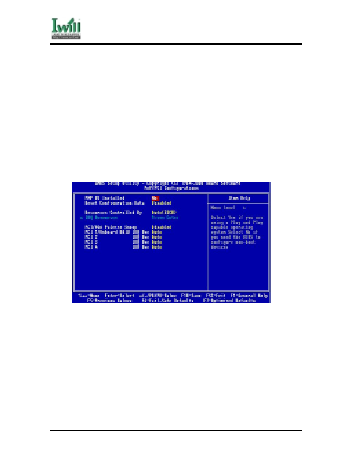
5.8 PnP/ PCI Configurations
5.8.1 PNP OS Installed
The field specifies whether a Plug and Play operating system is installed.
Options Yes
No (*)
5.8.2 Reset Configuration Data
Normally, you leave this field Disabled. Select Enabled to reset Extended System
Configuration Data (ESCD) when you exit Setup if you have installed a new add-on
and the system reconfiguration has caused such a serious conflict that the operating
system can not boot.
Options Enabled
Disabled (*)

69
VD133 Pro Series
Chapter 5 BIOS Setup
5.8.3 Resources Controlled By
The Award Plug and Play BIOS has the capacity to automatically configure all of the
boot and Plug and Play compatible devices. However, this capability means absolutely nothing unless you are using a Plug and Play operating system such as
WindowsÒ98/95/NT. If you set this field to “manual” choose specific resources by
going into each of the sub menu that follows this field (a sub menu is preceded by a
“Ø”).
Options Description
Auto (ESCD)(*) Resources controlled by BIOS automatically
Manual Resources controlled by the user
5.8.3.1 IRQ Resources
When resources are controlled manually, assign each system interrupt a
type, depending on the type of device using the interrupt.
5. 8. 3. 1 .1 IRQ3/4/5/7/9/10/11/12/14/15 assigned to
This item allows you to determine the IRQ assigned to the
ISA bus and is not available to any PCI slot. Legacy ISA for
devices compliant with the original PC AT bus specification,
PCI/ISA PnP for devices compliant with the Plug and Play
standard whether designed for PCI or ISA bus architecture.
Options PCI Device
Reserved
5.8.4 PCI / VGA Palette Snoop
This field controls the ability of a primary PCI graphics controller to share a common
palette with an ISA/VESA video or MPEG card
Options Description
Enabled PCI VGA co-works with ISA MPEG card
Disabled (*) All cases except above
5.8.5 PCI 1/ On board RAID IRQ Use
(On board RAIID VD133 Pro only)
This field determines the IRQ setting for PCI1. PC1 and PC2 may share the same IRQ,
or other options may be selected. The default setting for this field is Auto, which uses
automatic-routing to determine the setting.
Options Auto (*) / 3 / 4 / 5 / 7 / 9 / 10 / 11 / 12 / 14 / 15
5.8.6 PCI 2 IRQ Use
This field determines the IRQ setting forPCI2. The default setting for this field is
Auto, which uses automatic-routing to determine the setting.
Options Auto (*) / 3 / 4 / 5 / 7 / 9 / 10 / 11 / 12 / 14 / 15

70
VD133 Pro Series
Chapter 5 BIOS Setup
5.8.7 PCI 3 IRQ Use
This field determines the IRQ setting for PCI3. The default setting for this field is
Auto, which uses automatic-routing to determine the setting.
Options Auto (*) / 3 / 4 / 5 / 7 / 9 / 10 / 11 / 12 / 14 / 15
5.8.8 PCI 4 IRQ Use
This field determines the IRQ setting for PCI4. The default setting for this field is
Auto, which uses automatic-routing to determine the setting.
Options Auto (*) / 3 / 4 / 5 / 7 / 9 / 10 / 11 / 12 / 14 / 15
5.9 PC Health Status
This page is monitoring your status of computer. On the screen displays CPU/System
temperature, FAN speed, and voltages.

71
VD133 Pro Series
Chapter 5 BIOS Setup
5.10 IWILL Smart Setting
Over-clocking is not g uar anteed. Users must have substantial knowle dge
of proper CPU relativ e to adjusting CPU speeds. Ove r-clocking sh ould
be done only by experienced engineers who conduct tests.
5.10.1Auto Detect DIMM/PCI Clk
When enabled, the motherboard will automatically disable the clock source for a
DIMM socket, which does not have a module on it. This is true for all PCI slots.
Options Enabled (*)
Disabled
5.10.2Spread Spectrum
This item configures radiation emitted from the system. When enabled, system will
release less radiation.
Options Enabled
Disabled (*)
Over-clocking sometimes makes computer not work properly. You would
close the system and power and play ” insert” the key on the keyboard.
Waiting to see the monitor frame and set ”insert” key.

72
VD133 Pro Series
Chapter 5 BIOS Setup
5.10.3CPU / PCI Clock
This field allows user to adjust the CPU external frequency.
Options BY JUMPER
66/33MHz , 68/34MHz , 75/37MHz , 80/40MHz , 83/41MHz , 90/30MHz
95/31MHz , 100/133MHz , 103/34MHz ,105/35MHz , 1 10/36MHz ,
112/37MHz ,115/38MHz , 124/31MHz , 130/32MHz , 133/33MHz ,
135/34MHz ,138/34MHz ,140/35MHz , 144/36MHz , 150/37MHz ,
155/38MHz , 160/40MHz , 166/41MHz
5.10.4PU Clock Ratio:
Option 3/3.5/4/4.5/5/5.5/6/6.5/7/7.5/8
5.1 1 Load Fail-Safe Defaults
When you press <Enter> on this item you get a confirmation dialog box with a message similar
to:
Pressing ‘Y’ loads the BIOS default values for the most stable, minimal-performance system
operations.
on this item you get a confirmation dialog box with a message similar to:

73
VD133 Pro Series
Chapter 5 BIOS Setup
5.12 Load Optimized Defaults
When you press <Enter> on this item you get a confirmation dialog box with a message
similar to:
Pressing ‘Y’ loads the default values that are factory settings for optimal performance system
operations.
5.13 Set Supervisor / User Password Setting
These setup pages are used for password setting. When a password has been enabled and
the Security Option field is set as Setup, you will be required to enter the password every
time you try to enter BIOS Setup program. This prevents an unauthorized person from
changing any part of your system configuration. Additionally, if the Security Option field is
set as Boot, the BIOS will request a password every time your system boot. This would
prevent unauthorized use of your computer.
In you wish to use this function, bring the cursor to this field, then press <Enter>. The
computer will display the message, “Enter Password”. T ype your password and press <Enter>.
After the message onfirm Password” is displayed, re-type your password. The Supervisor
Password function will be in effect after you save and exit setup.
To disable a password, bring the cursor to this field, then press <Enter>. The computer will
display the message, “Enter Password”. Press <Enter>. A message will confirm that the
password is disabled. Once the password is disabled, the system will boot and you can enter
setup program freely.

74
VD133 Pro Series
Chapter 5 BIOS Setup
egnahctonnacuoytub,margorpputesSOIBretneotuoyswolladrowssaPresUehT
.ecalpefasnidrowssapruoypeekecalP.sdleifynafoeulaveht
5.14 Save & Exit Setup
Saves current CMOS value and exit BIOS setup program.
5.15 Exit Without Saving
Abandons all CMOS value changes and exits BIOS setup program.
Appendix
CPU FREQUENCY SETUP
In general, when adjusting the CPU frequency, you should select a matched bus frequency for
both the CPU and the motherboard. The reason is that your
CPU can only communicate with its external components at the same speed at
which the components operate. In other words, if your motherboard bus speed
is 100 MHz, you should start by selecting 100 MHz (as a “base”) to set the
CPU frequency. This frequency is also referred to as the “system bus
frequency” or external frequency.
T o understand how does CPU works, and how does it related to FSB and multiplier, here is the
example:
CPU speed = FSB x Multiplier (CPU Ratio)
800Mhz = 100Mhz x 8
How to setup CPU frequency in IWILL Smart Setting
IWILL provides a triple stepping system bus selection in VA series motherboards. It allows
user to select various FSB speed ranging from 66MHz ~ 166Mhz. This section will describe
how does this works.

75
VD133 Pro Series
Chapter 5 BIOS Setup
1 . Leave JP3A pin 2-3 ON & JP3B pin 2-3 ON, allows user to select the
following FSB.
66/75/83Mhz .
2 . Leave JP3A pin 2-3 ON & JP3B pin 1-2 ON, allows user to select the following FSB.
100/103/105/110/112/115/120/124 MHz.
3 . Leave JP3A pin 1-2 ON & JP3B pin 1-2 ON, allows user to select the following FSB.
133/140/150/166MHz
For example:
If you purchased a 800 MHz (133Mhz FSB) Intel® Pentium III CPU, leaves JP3A pin 1-2 ON &
JP3B 1-2 ON. Enter IWILL Smart Setting™, setup your CPU frequency by selecting 133 MHz
(system bus frequency) x 6 (multiplier), which equals 800MHz (your CPU frequency), saves it
in before leaving the BIOS setting to complete the CPU frequency setting.
If you purchased a 800 MHz (100Mhz FSB) Intel® Pentium III CPU, leave JP3A pin 2-3 ON &
JP3B pin 1-2 ON. Enter IWILL Smart Setting™, setup your CPU frequency by selecting 100
MHz (system bus frequency) x 8 (multiplier), which equals 800MHz (your CPU frequency),
saves it in before leaving the BIOS setting to complete the CPU frequency setting.
If you purchase a 533 MHz (66Mhz FSB) Intel® Celeron CPU, leave JP3A pin 2-3 ON & JP3B
pin 1-2 ON. Enter IWILL Smart Setting™, setup your CPU frequency by selecting 66MHz
(system bus frequency) x 8 (multiplier), which equals 533
MHz (your CPU frequency), saves it in before leaving the BIOS setting to complete the CPU
frequency setting.
However, the fact is, most of the CPU in the market now comes with multiplier locked. No effect
will be taken even the multiplier setting is altered in the IWILL Smart Setting. Furthermore, a
higher system bus frequency (FSB) has a much better performance than a slower system bus
frequency.
Note: BIOS will auto-detect and display your CPU Ratio (Multiplier).

76
VD133 Pro Series
Chapter 6 Power Installer CD
Chapter 6
Power Installer CD
6.1 Software Installation
The attached Power Installer CD contains all the necessary drivers, utilities for IWILL’s full
range of motherboards. It provides an easy way for users to install the needed drivers without
going through a complicated process. The Power Installer CD is able to auto-detect and
display the drivers, utilities needed for your motherboard.
6.1.1 What’s inside Power Installer CD for this motherboard
1. Drivers
Service Pack Driver
Sofware Audio Driver
High Point XStore Pro
A ward Patch File
2. Utilities
Anti-Virus
Hardware Monitor Utility(Window9X only)
Suspend To Disk
Acrobat Reader
3. Manuals
6.2 How to use the Power installer CD
The Power Installer CD supports the Auto Run program under Windows 98/95 and Windows
NT operating systems. All the necessary drivers, utilities and manual for this motherboard will
show on the screen. Select the one that needs to be installed, then simply follow the messages
displayed on the screen to complete setup.
esutsumuoY.tnemomsihttadraobyekatroppustonseodrellatsnIrewoPLLIWI
.tillatsniotesuoma

77
VD133 Pro Series
Chapter 6 Power Installer CD
6.2.1 How to view manual
This Power Installer CD includes detailed information of all IWILL manuals for every
motherboard manufactured by IWILL. Please insert the IWILL Power Installer CD
into the CD-ROM drive; Click the “View Manual” item, and select the product that
you want to view.
6.2.2 How to make driver diskette
6.2.2.1 Without O.S. installed
This bootable Power Installer CD also allows you to boot up your system,
even when the OS has not been installed. During the boot-up process,
you can perform “IWILL Diskette Creator,” which will automatically make
the driver diskettes you need.
ekamotyrasseceneraevirdyppolfM44.1enodnaevirdMOR-DCenotsaeltA
.ylreporpkrow""rotaerCetteksiDLLIWI""
Follow the instructions below to make your own device driver floppy
diskettes if you have a CD-ROM with IDE interface. If you have already
installed SCSI CD-ROM, please make sure your SCSI host adapter supports bootable CD-ROM, and then proceed directly to step 8 , and then
finish the procedure.
1. First, power-on or “boot” your system.
2. Press <Del> key during boot sequence to enter
“ CMOS Setup Utility”
3. Use arrow keys to select “ADV ANCED BIOS FEA TURES” on the
menu, then press “Enter.”
4 . Select “First Boot Device” and change the default setting from
“Floppy” to “CDROM” using Page Up /Page Down key.
5 . Press <Esc> key to go back to CMOS SETUP Utility menu.
6. Press <F10> to select “Save and Exit Setup”
7. Press “Y” then “Enter” to complete. Now you are able to boot up
the system from the CD-ROM.
8 . Insert the Power Installer CD into the CD-ROM drive and re-start
the computer.
9 . IWILL Diskette Creator will now execute automatically for making
your own driver diskettes.
10. Make the desired driver diskettes according to the instructions
displayed on screen.
6.2.2.2 Under windows 98/95/NT
You may just click on the software Make Driver Diskettes Utility shown
on screen, then select the driver you need, follow the messages shown on
screen to complete.

78
VD133 Pro Series
Chapter 6 Power Installer CD
6.2.4 How to install VIA Service Pack(4 in 1. EX: Bus Master,
ACPI, IRQ, AGP)
Simply click on the software shown on screen that needs to be installed, then simply
follow the messages displayed on the screen to complete setup.
Simply click on the software shown on screen that needs to be installed, then simply
follow the messages displayed on the screen to complete setup.
6.2.5 How to install Award Patch File Driver
You may just click on the Award Patch File Driver shown on screen that needs to be
installed, then follow the prompts to complete setup.
6.2.6 How to install Software Audio Driver
You may just click on the Software Audio Driver shown on screen that needs to be
installed, then follow the prompts to complete setup.
6.2.7 How to use Anti-Virus program
Simply click on the Anti-Virus shown on screen that be installed, then follow the
prompts to complete setup.
6.2.8 How to use Hardware Monitoring Utility(Window 9X only)
Y ou may just click on the Hardwar e Monitor Utility shown on screen then follow the
prompts to complete setup.

79
VD133 Pro Series
Chapter 6 Power Installer CD
6.3 Installing Operating Systems
This section briefly demonstrates how to install a few popular software operating systems.
Use this section only as a guide. It is highly recommended that users first refer to the installation manual of their operating system for a more thorough, detailed description on how to
install the operating system.
6.3.1 Windows 98
Whenever installing Windows 98, please remember that Setup creates a new folder for
Windows 98, and won’t transfer any existing system settings. Windows 98 will become your default operating system, and will use standard system settings. This
procedure represents an entirely new installation of Windows, therefore you’ll need
to reinstall any existing programs you may want to use.
There are two ways to install Windows 98. Each method depends on your current
computer setup.
ehtgnisusemitlarevestratseryllacitamotualliwretupmocruoy,puteSgniruD
.draziwputeS89swodniW
6.3.1.1 Installing the CD-ROM version of Windows 98
1 . Place a Windows 98 Startup Disk into the floppy disk drive.
2. Restart your computer.
The Microsoft Windows 98 Startup menu will appear.
3 . Place the Windows 98 CD into your CD-ROM drive.
4 . Type the number 1 and press <ENTER >.
A series of scans is performed, and then the MS-DOS prompt is
displayed.
5 . Type the word setup at the MS-DOS display, and press <ENTER>.
Setup performs a check (A message will be displayed).
This message won’t appear if your computer can’t locate your CDROM drive. If you haven’t installed the correct CD-ROM driver,
please consult your drive’s documentation or contact your hard
ware manufacturer.
6. Press <ENTER>.
Microsoft ScanDisk will check your disk drives for errors.
7. When ScanDisk finishes, press the X key.
Setup will initialize. Then, Windows 98 Setup begins.
8. Please follow the instructions that are displayed.
er'uoyfisksid1.3swodniWro59swodniWlanigiroruoytresniotuoyksayamputeS
.89swodniWfonoisrevedargpuehtgnisu

80
VD133 Pro Series
Chapter 6 Power Installer CD
6.3.2 Windows NT
6.3.2.1 Installing the CD-ROM version of Windows NT on an IDE system
1. First, power-on or “boot” your system.
2. Press <Del> key during boot sequence to enter “ CMOS Setup
Utility”
3 . Use arrow keys to select “BIOS FEATURES SETUP” on the menu,
then press “Enter.”
4. Select “Boot Sequence” and change the default setting from A, C,
SCSI to “CD-ROM, C, A” using Page Up /Page Down key.
5 . Place the Windows NT 4.0 CD-ROM in the drive.
6 . Follow all instructions to finish Windows NT installation.
 Loading...