


Table of Content
Quick Installation ................................................ 3
1.1 Layout............................................................................3
1.2 Item Checklist ...............................................................4
1.3 Jumpers ........................................................................4
1.4 Connectors ...................................................................7
1.5 Form Factor.................................................................12
Feature ................................................................ 14
2.1 Motherboard Components Placement.....................14
2.2 Block Diagram ............................................................16
2.3 Specifications .............................................................17
Hardware Setup.................................................20
3.1 Before Installation ......................................................20
3.2 Install the Processor ..................................................21
3.3 Install Memory Modules ............................................25
3.4 ATX Power Supply connector ...................................27
3.5 Back Panel ..................................................................29
VA133plus version 1.0A
1
FB11342360000

Chapter 1 Quick Installation
BIOS Setup......................................................... 30
4.1PhoenixNet Introduction.............................................30
4.2 BIOS Setup..................................................................33
4.3 Main Menu ...................................................................35
4.4 Standard CMOS Features ..........................................36
4.5 Advanced BIOS Features...........................................41
4.6 Advanced Chipset Features ......................................47
4.7 Integrated Peripherals................................................51
4.8 Power Management Setup.........................................56
4.9 PnP/ PCI Configurations ............................................62
4.10 PC Health Status ......................................................65
4.1 1 Iwill Smart Setting .....................................................66
4.12 Load Fail Safe Defaults ............................................71
4.13Load Optimized Defaults ..........................................72
4.14 Set Supervisor/ User Password Setting .................73
4.15 Save & Exit Setup .....................................................75
4.16 Exit Without Saving ..................................................76
Power Installar CD ............................................78
5.1 Software Installation...................................................78
5.2 How to use the Power installer CD ...........................79
5.3 How to make driver diskette ......................................79
5.4 Install Driver ................................................................81
5.5 Install Software Utility.................................................82
2

Chapter 1 Quick Installation
1 Quick Installation
1.1 Layout
3

Chapter 1 Quick Installation
1.2 Item Checklist
[V ] The motherboard
[V ] Operation manual
[V ] ATA/66 cable
[V ] Floppy cable
[V ] Power Installer CD
Optional
[ ] USB riser kit
[ ] Thermal Sensor for System
[ ] Display Cache Riser Card
1.3 Jumpers
1.3.1Clear CMOS jumper(CMOS, JP1)
4

Chapter 1 Quick Installation
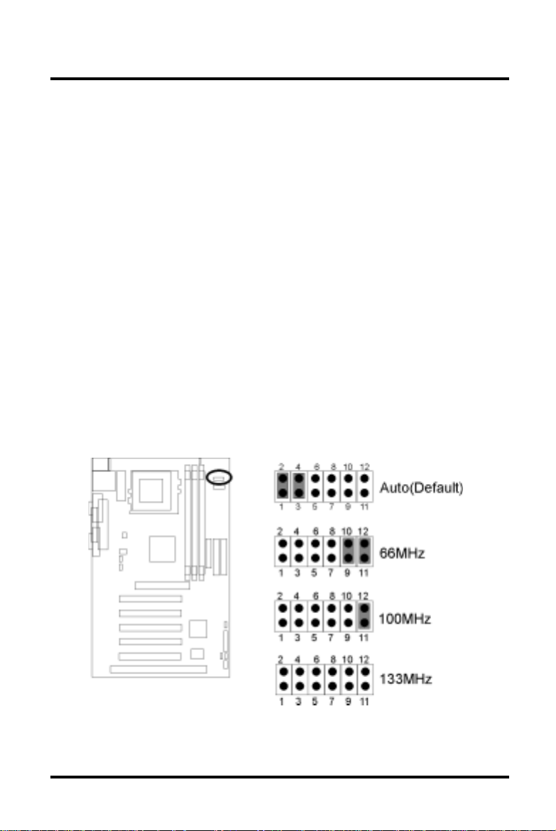
1.3.2CPU FSB select jumper(FSB, JP3 )
1.3.3 VIO select jumper (VIO, JP10)
v
5

Chapter 1 Quick Installation
1.3.4 Vcore booster jumper (Vcore, JP9)
The motherboard will auto detect the CPU Vcore Voltage.
However, there are 16 various vcore setting offered on
motherboard to satisfy the needs for overcloking.
WARN: A wrong voltage setting will cause irreversible
pemanent damage to the CPU.
erocVA9PJB9PJC9PJD9PJ
(otuA tluafeD ) NO2-1 NO2-1 NO2-1 NO2-1
V03.1FFOFFOFFOFFO
V53.1NO3-2FFOFFOFFO
V04.1FFONO3-2FFOFFO
V54.1NO3-2NO3-2FFOFFO
V05.1FFOFFONO3-2FFO
V55.1NO3-2FFONO3-2FFO
V06.1FFONO3-2NO3-2FFO
V56.1NO3-2NO3-2NO3-2FFO
V07.1FFOFFOFFONO3-2
V57.1NO3-2FFOFFONO3-2
V08.1FFONO3-2FFONO3-2
V58.1NO3-2NO3-2FFONO3-2
V09.1FFOFFONO3-2NO3-2
V59.1NO3-2FFONO3-2NO3-2
V00.2FFONO3-2NO3-2NO3-2
V50.2NO3-2NO3-2NO3-2NO3-2
6

Chapter 1 Quick Installation
1.4 Connectors
1.4.1CPU fan header (J39)
1.4.2System fan header (J41)
1.4.3Infrared connector (IR)
7

Chapter 1 Quick Installation
1.4.4Wake-ON-LAN header
1.4.5Internal Modem header
8

Chapter 1 Quick Installation
1.4.6ATX power connector (J37)
9

Chapter 1 Quick Installation
1.4.7System temp.sensor header
1.4.8Front panel connector (J43)
10

Chapter 1 Quick Installation
11

Chapter 1 Quick Installation
1.5 Form Factor
12

Chapter 1 Quick Installation
13

Chapter 2 Feature
2 Features
2.1 Motherboard Components Placement
14

Chapter 2 Feature
[
.ONnoitpircseD
1rotcennocrewoPXTA
2A396AIV
3073tekcolSfoUPC
4stetkcolsMMID
5
6
7tolsPGA
8A686C28TVAIV
9tolsASI
01stolsICP
112MOC
11rotcennoclellaraP
311MOC
41stropBSU
51draobyeK/suoM2SP
rotcennocksiDyppolF
srotcennocEDIht2dnaht1
15

Chapter 2 Feature
2.2 Block Diagram
16

Chapter 2 Feature
2.3 Specifications
Processor/Socket 370
Support 1 processor through Socket370 socket
Supports 66M/100M/133MHz FSB
Support Intel Celeron (Mendochino, PPGA) CPU from 300A and +.
Support Intel Celeron (Cu-128, FCPGA) CPU from 533A to
700+MHz
Support Intel Pentium III (Cu-256, FCPGA) CPU from 500 to 1GHz+
Support Cryix Samuel CPU from 433 to 500+MHz
CPU Frequency Select
Support S/W CPU speed auto detect method
Support “Software assign ext. frequency” up to 166MHz (3 Steps
Bye Bye Jumper)
Support “Software assign CPU Multipier” from 3X to 12X
Support Vcore selection by jumper
Support VIO selection by jumper
Memory
Support PC66/PC100/PC133 SDRAM
Support EDO,SDRAM,ESDRAM,VCM SDRAM
Support 16M/64M/256M SDRAM technology
Maximum memory up to 1.25GB/768MB when using 256M/
64M-16M technology
Support 3.3V Unbuffered / Registered DIMM
Support Single-sided/Double-sided DIMMs
Support ECC memory module
17

Chapter 2 Feature
Graphics
Supports 2X AGP mode
IDE
Support 2 channel IDE interface up to 4 IDE Devices.
Support Ultra DMA Bus Master with 66 MB/s burst data transfer
rate.
Support PIO mode up to Mode 4.
Support LS120/ZIP drive.
USB
Support 2 UHCI Universal Serial Bus Port
Management
Support ACPI 1.0 and APM
Support PCI PME# signal
Support SMBus
Expansion Slot
Three DIMM sockets
One AGP Slot
Five PCI Slots
One ISA Slot
Two IDE connectors
One FDC connectors
18

Chapter 2 Feature
Power Plane
Support VRM 8.4
Support adjustable Vcore (16 settings 1.3~2.05V by 0.05V)
Support adjustable Vio (Normal/Increase 5% & Increase 10%)
Others
Form Factor A TX 30.5 X 19.3 cm
19

Chapter 3 Hardware Setup
3 Hardware Setup
3.1 Before Installation
For installation, you may need some or all of the following tools:
Medium size flat blade screwdriver
Medium size Phillips head screwdriver
A 3/16 inch nut driver or wrench
ehterusneotsenilediugesehtwolloftsumsresU
.noitallatsnigniruddetcetorpsidraobrehtom
nevenehwffo-derewopsiretupmocruoyerusekaM.1
stnenopmocedisnihtiwnikrow
si,tnempiuqecinortcelerehtollaekil,draobrehtomehT.2
snoituacerpreporpehtekatesaelP.citatsotevitisnes
agnihcuotybflesruoydnuorg,elbissopfI.tignildnahnehw
evitcudnocstinidraobehtpeek.ksedroelbatlatem
nidellatsniebotydaerdnaderugifnocsitilitnugnipparw
.metsysruoy
yppolfdnadrahruoyhtobmorfyawastengamllapeeK.3
htobpeeK.srevirdwercscitengamyllaicepse,sevirdksid
.debmessasidfitrapasksiddrahdnayppolf
stidnaretupmocruoymorfyawasdiuqildnaretawpeeK.4
.stnenopmoc
20

Chapter 3 Hardware Setup
3.2 Install the Processor
tneverpottiotdehcattanafaevahdluohsUPCehT
nafaesahcrupneht,esacehttonsisihtfI.gnitaehrevo
.metsysruoynonrutuoyerofeb
ehtssorcanoitalucricriatneiciffussierehttahteruseB
ruoytahtgnikcehcylralugerybknistaehsrossecorp
eht,noitalucrictneiciffustuohtiW.gnikrowsinafUPC
ehthtobegamaddnataehrevodluocrossecorp
nallatsniyamuoY.draobrehtomehtdnarossecorp
.yrassecenfi,nafyrailixua
21

Chapter 3 Hardware Setup
Step1:
Locate the ZIF socket and open it by first pulling the lever of socket
upward.
Step2:
Insert the CPU into the socket. Please keep the lever right angle
when inserting CPU.
22

Chapter 3 Hardware Setup
Step3:
When inserting the CPU please note the correct orientation as
shown. The notched corner should point toward the end of the
lever.
Step4:
Push the lever down to close the socket.
23

Chapter 3 Hardware Setup
Step 5:
Attach the heatsink onto the CPU.
Step6:
Push the clip of heatsink downward to hock the ear of socket firmly.
Step7:
Finally, attach the fan cable to the CPU fan header FCPU.
24

Chapter 3 Hardware Setup
3.3 Install Memory Modules
The motherboard has three Dual Inline Memory Module (DIMM)
sockets and supports the maximum memory size up to 1.5GB.
These DIMM sockets only support 3.3V unbuffered SDRAM
modules. The motherboard also support SPD (Serial Presence
Detect) architecture to provide the best choice for performance vs.
stability.
Step 1:Open latches of DIMM socket
Step 2:Proofread the RAM module to the DIMM Socket.
25

Chapter 3 Hardware Setup
Step 3:Insert the RAM module into the DIMM socket.
Step 4:Press the latches into the notches of the RAM module.
26

Chapter 3 Hardware Setup
3.4 A TX Power Supply Connector
3.4.1Power on procedures
PETSnoitpircseD
1
2.ffoerasehctiwsllatahteruseB
3
4
5
6
esacmetsysehtesolc,edamerasnoitcennocllaretfA
.revo
detacolylpppusrewopehtotnidrocrewopehttcennoC
.esacmetsysruoyfokcabehtno
deppiuqesitahtteltuorewopadraocrewopehttcennoC
.rotcetorpegrusahtiw
aybV022/V011troppusylppusrewopehtfoynaM
tcerrocehtotylppusrewopruoyhctiwS.gnitteshctiws
.egatlovylppus
redrogniwollofehtnimetsysruoynonruT
rotinomehT.a
.secivedlanretxeehT.b
.metsysretupmocehT.c
27

Chapter 3 Hardware Setup
lliwsissahcehtfolenaptnorfehtnoDELrewopehT
-rewopnurnehtlliwmetsyseht,sdnoceswefretfA.thgil
ehtnoraeppalliwsegassemlanoitiddaemoS.stsetno
nihtiwgnihtynaeestonoduoyfI.tsetehtgnirudneercs
eht,rewopehtnonrutuoyemitehtmorfsdnoces03
ehtkcehceR.tsetno-rewopadeliafevahyammetsys
rofreliaterruoyllacrosnoitcennocdnasgnittesrepmuj
.ecnatsissa
3.4.2Power off procedures
PETSnoitpircseD
1.snoitacilppaerawtfosehtllamorftixE
2.metsysgnitareporuoynwodtuhs
niWgnisuerauoyfI.nottubrewopffohctiwS
3
.nwodtuhsswodniWretfayllacitamotua
ffomrutdluohsylppusrewopeht,eM89/TN/0002/X9
4.secivedlanretxellaffonruT
5.rotinomruoyffonruT
28

Chapter 3 Hardware Setup
3.5 Back Panel
noitcnuF roloc noitpircseD
-suoM/2SP
e
/2SP
draobyek
neerG
elpruP
esuom2/SPa
.draobyek2/SPa
troppusotdesuebnacrotcennocsihT
troppusotdesuebnacrotcennocsihT
,stropBSUowtsahdraobrehtomsihT
lasrevinU
suBlaireS
kcalB
slarehpirepelbitapmoc-BSUyna
otnidetcennocebnacbuhro/dna
.tropBSUrehtie
v
troplaireS
&1MOC
2MOC
lelleraP
trop
laeT
ydnugruB
.secivedlairesrehtoro
.secivedlellaraprehto
medomarofydaersitroplairesowT
ro,sretnirprofdesusirotcennocsihT
-otuaebnacdraobyek2/SPdnaesuom2/SPehT
gulpuoyfisnaemtahT.draobrehtomsihtybdetceted
nacllitsti,rotcennocesuomehtotnidraobyek2/SPeht
sitI.asrevecivdnaelbuortynatuohtiwkrow
erofebretupmocehtffonrutuoytahtdednemmocer
.esuomro/dnadraobyekgnitcennocsidrognitcennoc
29

Chapter 4 BIOS Setup
4 BIOS Setup
4.1 PhoenixNet Introduction
PhoenixNet is a service that provides PC users with best-of-breed,
free, software services to support their PC hardware and software
and to turn their computer into a powerful tool for communication,
entertainment, education and business
4.1.1Internet Launch System
The PhoenixNet Internet Launch System (ILS) is a patentpending technology built into the firmware to enable online
PC users worldwide to communicate with PhoenixNet and to
receive the free PhoenixNet services. ILS resides safely
within ROM and is activated the first time a user launches a
PhoenixNet-enabled PC with a Windows 98 Operating
System.
4.1.2PhoenixNet Online Services
When the PhoenixNet ILS detects an Internet connection, it
makes contact with the PhoenixNet server and delivers userselectable services from PhoenixNet’s Internet Partners.
These services are delivered to the user as hotlinks on the
desktop and in the web browser or, as applications that
PhoenixNet automatically packages, downloads and
installs.
30

Chapter 4 BIOS Setup
4.1.3PhoenixNet Online Services
selifruoydnaretupmocruoytcetorp&eganaM
moc.pleHyawevirDmoc.surivitnA
lootnoitacinummocaotniretupmocruoynruT
erahSevitcAebodAklaTeriFklaTtekcoR
retnectnemniatretnenaotniretupmocruoynruT
oidaRteNxoBekuJlaeR
enilnognippohsnehwyenomdnaemitevaS
moc.TENCnomiSyM
beWehtfotseB¡K
LOA:sPSIoohaYeticxEpanSsocyL:slatroP
31

Chapter 4 BIOS Setup
4.1.4User Boot
1
2
3.ecivresteNxineohPstcejeR/stpeccaresU
4.yrentrapPSIteNxineohPstcejeR/stpeccaresU
5.potksednoraeppanociPSIdnateNxineohP
.EBOO
4.1.5Internet Access
1.stluafedresworb&snocipotksedstesteNxineohP
2
3
4yrtnuocdnaliam-e,emansretneresU
.secivres
cihpargmorfnoitamrofnimetsyssdaerresU
.neercShcnuaL
SMsetelpmocdnaswodniWSMsretsigerresU
otgniknilsraeppawodniwresworbweN
moc.tenxineohp.www .
&erawtfosrentraptenxineohPstcelesresU
5
6.liam-eybdraweryratenomseviecerresU
7
rentrapdetcelessllatsnidnasdaolnwodteNxineohP
.kcilc-esuomenohtiw,dnuorgkcabehtnierawtfos
otsecivresteNxineohPgniognoseviecerresU
.ecneirepxetenretnIdnaCPriehtecnahne
32

Chapter 4 BIOS Setup
4.2 BIOS Setup
4.2.1Upgrade BIOS
The BIOS can be upgraded from a diskette with the Award
Flash utility — AWDFLASH.EXE. The BIOS image file, and
update utility are available from IWILL’s WEB site: www.
iwill.net
4.2.2Enter BIOS setup program
Power-on the system by either pressing the Power-On
button, or by using any of the power-on features provided by
the motherboard. Then, press the <Del> key after the
Power-On Self Test (POST), and before the scanning of IDE
devices. Simply look for the message “Press DEL to enter
SETUP” displayed at the bottom of the screen during the
boot up process. If the message disappears before you’ve
had a chance to respond, you can restart the system by
Turning off the system power then turn it on again, or
Pressing the “RESET” button on the system case, or
Pressing <Ctrl>, <Alt> and <Del> keys simultaneously.
ylluferacneebevahsgnittestluafedSOIBeht,yllareneG
ehtedivorpotrerutcafunammetsysehtybnesohc
yrevsitI.ytilibailerdnaecnamrofrepmumixametulosba
lluftuohtiwgnittesynaegnahcotsuoregnad
.uoytahtdnemmocerylgnortseW.gnidnatsrednu
.yltcefrepskrowmetsysehtfiSOIBruoyetadpuTONOD
dnatsrednuyllufuoysselnugnittesynaegnahcTONOD
.snaemtitahw
33

Chapter 4 BIOS Setup
4.2.3Using BIOS setup program
ÇUp Mov e t o the pr evious field
ÈDown Move to the next field
ÅLeft
ÆRight
<Esc>
<PgUp> or
<+>
<PgDn> or <-> Select the next value for a field
<F1> General Help
<F2> Item Help
<F5> Previous Values
<F6> Fail-Safe Defaults
<F7> Optimized Defaults
<F10>
Move to the field on the left hand
side
Move to the field on the right hand
side
Quit f r om setup program wi th out
saving chang es, or Exit fr om
current menu page and return to
mai n menu page
Select t h e p revi o u s v alue for a fiel d
Save the current value and exit
setup program
If the system is no longer able to boot after changing the settings,
the only way to recover it is to clear the data stored in RTC CMOS.
To reset the RTC CMOS data, take the JP1 jumper cap off pins 1-2,
place onto pins 2-3, and then place back onto pins 1-2 again. This
will return the RTC to the default setting. Then, get into the BIOS
setup program , choose Load Fail-Safe Defaults ; Load Optimized
Defaults, and select the original manufacturer default settings in
your CMOS.
34

Chapter 4 BIOS Setup
4.3 Main Menu
The main menu allows you to select from several setup pages. Use
the arrow keys to select among these pages and press <Enter>
key to enter the sub-menu. A brief description of each highlighted
selection appears at the bottom of the screen.
35

Chapter 4 BIOS Setup
4.4 Standard CMOS Features
4.4.1Date
This field specifies the current date. The date format is
<month>, <day>, and <year>.
4.4.2Time
This field specifies the current time. The time format is
<hour>, <minute>, and <second>. The time is calculated
based on the 24-hour (military-time) clock.
36

Chapter 4 BIOS Setup
4.4.3IDE Primary Master / Primary Slave /
Secondary Master / Secondary Slave
Press “Enter” to enter next page for detail hard drive setting.
4.4.3.1 IDE HDD Auto-Detection
Auto-Detect the HDDs Capacity, and its parameters,
ex: Cylinder, Head and Sector.
4.4.3.2 IDE Primary Master / Primary Slave / Secondary Master
/ Secondary Slave
This field specifies type of drive that corresponds to
the drive installed in your system. If you select User,
please specify the correct number of Cylinders,
Heads, and Sectors.
gniniamerehttesuoystellaunagnitceleS
launaM
.ksiddexif
foepytehtstceleS.neercssihtnosdleif
otuA
)eluaVtluafeD(
enoNdehcattaerasevirDksiDynA
4.4.3.3 Capacity Auto Display your disk drive size
4.4.3.4 Access MODE
This field specifies the IDE translation mode.
LAMRON
EGRAL
ABL.edomnoitalsnartABLseificepS
OTUA
)eluaVtluafeD(
.edom
edom
.yllacitamotua
37
ehtrofseulavehtnisllifyllacitamotuaSOIB
.sdleifsrotcesdnasdaeh,srednilyc
gnisserddaSHClanoitidartseificepS
noitalsnartSHCdednetxeseificepS
dohtemnoitalsnartseificepsSOIB

Chapter 4 BIOS Setup
4.4.3.5 Cylinders
Set the number of cylinders for this hard disk.
4.4.3.6 Heads
Set the number of read/write heads
4.4.3.7 Precomp
Setting a value of 65535 means no hard disk
4.4.3.8 Sectors
Set the number of sectors per track
4.4.4Drive A / Drive B
This field specifies the traditional type of floppy drives.
enoN
)tluafedBevirD*(
.ni52.5,K063
.ni52.5,M2.1detcennocsievirdyppolfM2.1A
.ni5.3,K027.detcennocsievirdyppolfK027A
.ni5.3,M44.1
)tluafedBevirD*(
.ni5.3,M88.2detcennocsievirdyppolfM88.2A
edom
4.4.5Floppy 3 Mode Support
3 Mode floppy drive is a type of 3.5-inch drive used by NEC
PC98 computers. It supports both 1.2M and 1.44M formats
using the same drive. This field specifies which drive
supports 3 Mode. When a floppy drive is specified to support
3 Mode, the respective drive setting in “Drive A / Drive B” field
will be invalid.
detcennocsievirdyppolFynA
noitalsnartSHCdednetxeseificepS
detcennocsievirdyppolfM44.1A
38

Chapter 4 BIOS Setup
AevirDAevirdsadetcennocsievirdedoM3A
BevirDBevirdsadetcennocsievirdedoM3A
htoB
4.4.6Video
ONOMretpadaemorhconoMseificepS
4.4.7Halt On
delbasiD
)eulaVtluafeD(
sevird
AGV/AGE
)eulaVtluafeD(
04AGC
08AGC
srorrEllA
)eulaVtluafeD(
edom
edom
egassemrorre
ddetcennocsievirdedoM3oN
edoM3eraBevirddnaAevirdhtoB
dretpadaAGVroAGEseificepS
nmuloc04htiwretpadaAGCseificepS
nmuloc08htiwretpadaAGCseificepS
lataf-nonastcetedSOIBehtemithcaE
nayalpsiddnapotslliwmetsyseht,rorre
srorrEoN
draobyeKtuB,llA
etteksiDtuB,llA
yeK/ksiDtuB,llA
39
detcetedera
rorredraobyektpecxe
rorreetteksidtpecxe
tahtsrorreynarofpotslliwmetsysehT
srorreynarofpotslliwmetsysehT
srorreynarofpotslliwmetsysehT
srorreynarofpotslliwmetsysehT
srorredraobyekdnaetteksidtpecxe

Chapter 4 BIOS Setup
4.4.8Base Memory
The POST (Power-On Self T est) determines the amount of
base (conventional) memory installed in the system. The
value of the base memory is typically 640K. This field has no
options.
4.4.9Extended Memory
The BIOS determines how much extended memory is
present during the POST. This is the amount of memory
located above 1MB in the processor’s memory address map.
This field has no options.
4.4.10T otal Memory
Displays the total memory available in the system
40

Chapter 4 BIOS Setup
4.5 Advanced BIOS Features
41

Chapter 4 BIOS Setup
4.5.1Anti-Virus Protection
When this function is enabled, the BIOS monitor the boot
sector and partition table of the hard disk drive for any
attempt at modification. If an attempt is made, the BIOS will
halt the system and then display an error message.
Afterwards, if necessary, you can run an anti-virus program
to locate and remove the problem before any damage is
done.
Many disk diagnostic programs will attempt to access the
boot sector table, which can cause the above warning
message. If you run such a program, we recommend that
you first disable the Virus Warning function beforehand.
delbasiD,elbanE )eulaVtluafeD(
4.5.2CPU Internal Cache
This field configures the CPU internal cache (L1 cache).
elbanE )eulaVtluafeD( delbasiD,
4.5.3External Cache
This field configures the system’s external cache (L2 cache).
elbanE )eulaVtluafeD( delbasiD,
4.5.4CPU L2 Cache ECC Checking
This field specifies whether the CPU L2 cache supports ECC
or not.
delbasiD,elbanE )eulaVtluafeD(
4.5.5 Proccessor Number Feature
delbasiD,elbanE )eulaVtluafeD(
42

Chapter 4 BIOS Setup
4.5.6Quick Power On Self Test
This field allows the system to skip certain tests while
booting. This will decrease the time needed to boot the
system.
elbanE )eulaVtluafeD( delbasiD,
4.5.7First / Secondary / Third / Other Boot Device
The BIOS attempts to load the operating system from the
devices in the sequence selected in these items.
,2-DDH,1-DDH,MORDC,ISCS,0-DDH,PIZ/SL,yppolF
delbasiD,NAL,3-DDH
4.5.8Swap Floppy Drive
When enabled, floppy drives A and B will be exchanged
without the user physically changing the connection on the
cable.
delbasiD,elbanE )eulaVtluafeD(
4.5.9Boot Up Floppy Seek
Seeks disk drives during boot up. Disabling speeds boot up.
elbanE )eulaVtluafeD( delbasiD,
4.5.10Boot Up Num Lock Status
This field determines the configuration of the numeric keypad
after system boot up. If On, the keypad uses numbers keys.
If Off, the keypad uses arrow keys.
NO ,)eulaVtluafeD( ffO
43

Chapter 4 BIOS Setup
4.5.1 1Gate A20 Option
This field configures how the gate A20 is handled. The gate
A20 is a device used to address memory above 1 MB. At
first, the gate A20 was handled from a pin on the keyboard.
While some keyboards still provide this support, it is more
common, and much faster, for modern system chipsets to
provide support for gate A20.
tsaF.cigolerocybdetroppuslangis02AetaG
lamroN
eluaVtluafeD( )
.rellortnoc
4.5.12Typematic Rate Setting
This field determines if the typematic rate is to be used.
When enabled, the BIOS will report (after a moment) that the
key has been depressed repeatedly. When disabled, the
BIOS will report only once if a key is held down continuously.
This feature is used to accelerate cursor movements using
the arrow keys.
delbasiD,elbanE )eulaVtluafeD(
4.5.13Typematic Rate (Chars/Sec)
When Typematic Rate Setting enabled, this field specifies
how many characters will be displayed in one second when
a key is held down continuously.
6 )eulaVtluafeD( 03,42,02,51,21,01,8
draobyekybdetroppuslangis02AetaG
44

Chapter 4 BIOS Setup
4.5.14T ypematic Delay (Msec)
When enabled, typematic delay allows you to select the time
delay between when the key is first pressed and when the
acceleration begins.
cesm052 )eulaVtluafeD( cesm0001,cesm057,cesm005
4.5.15Security Option
This field configures how the system security is handled. It
works conjunction with SETTING SUPERVISOR / USER
P ASSWORD page to control the security level of the system.
puteS
)eulaVtluafeD(
metsyStoobotdrowssapasdeenmetsyS
margorpputes
4.5.16OS Select for DRAM >64MB
When enabled, this field allows you to access the memory
that is over 64MB under OS/2.
2SO-noN,2SO )eulaVtluafeD(
4.5.17Report No FDD For WIN 95
For a floppy diskless system that runs Windows 95, this field
should be set to Yes.
ON,SEY )eulaVtluafeD(
v
SOIBretneotdrowssapasdeenmetsyS
45

Chapter 4 BIOS Setup
4.5.18Video BIOS Shadow
When enabled, the video BIOS will be copied to system
memory and increase the video speed.
elbanE )eulaVtluafeD( delbasiD,
4.5.19C8000-CBFFF/CC000-CFFFF/D0000-D3FFF
Shadow
D4000-D7FFF/D8000-DBFFF/DC000-DFFFF
Shadow
delbasiD,elbanE )eulaVtluafeD(
46

Chapter 4 BIOS Setup
4.6 Advanced Chipset Features
This setup page is used to specify advanced features available
through the chipset. The default settings have been chosen
carefully for most operating conditions. DO NOT change the value
of any field in this setup page without full understanding.
47

Chapter 4 BIOS Setup
SDRAM Settings
The first chipset settings deal with CPU access to SDRAM.
The default timings have been carefully chosen and should
only be altered if data is being lost. Such a scenario might
well occur if your system had mixed speed SDRAM chips
installed. Longer delays might result, however this preserves
the integrity of the data held in the slower memory chips.
4.6.1SDRAM Cycle Length
When synchronous DRAM is installed, the number of clock
cycles of CAS latency depends on the DRAM timing. Do not
reset this field from the default value specified by the system
designer.
3,2 )eulaVtluafeD(
4.6.2SDRAM Bank Interleave
Select numbers of Bank to Bank to realize fast and
seamless data access mode amony many different pages.
(DPSyB eluaVtluafeD sknaB4,sknaB2,)
4.6.3DRAM Clock
This field allows you to select the DRAM operating frequency
to get better performance.
klCtsoH
)eulaVtluafeD(
zHM33-KLCH
zHM33+KLCH
suBediS
suBediStnorF
suBediStnorF
48
tnorFsadeepsemasehtsikcolcMARD
ehtnahtsselzHM33tessikcolcMARD
ehtnahteromzHM33tessikcolcMARD

Chapter 4 BIOS Setup
4.6.4DRAM Parity/ECC check
delbasiD,elbanE )eulaVtluafeD(
4.6.5 Memory Hole
In order to improve performance, certain space in memory is
reserved for ISA cards. This memory must be mapped into
the memory space below 16MB.
delbasiD,M61-M51 )eulaVtluafeD(
4.6.6System BIOS Cacheable
When enable accesses to the system BIOS will be cached
elbanE )eulaVtluafeD( delbasiD,
4.6.7 Video RAM Cacheable
When enabled, access to the video memory located at
A0000H to BFFFFH will be cached.
delbasiD,elbanE )eulaVtluafeD(
4.6.8 AGP Aperture Size
This field specifies the size of system memory that can be
used for AGP graphics aperture.
M46,M23,M61,M8,M4 )eulaVtluafeD( M821,
4.6.9AGP-2X Mode
This item allows you to enable/disable the AGP-2X Mode.
elbanE )eulaVtluafeD( delbasiD,
49

Chapter 4 BIOS Setup
4.6.10PCI Dynamic Bursting
When enabled, every write transaction goes to the write
buffer, and burstable transactions will then burst on the PCI
bus, and non-burstable transactions won’t burst on the PCI
bus.
When disabled, if the write transaction is a burst transaction,
the information goes into the write buffer and burst transfers
are later performed on the PCI bus. If the transaction is not a
burst transaction, PCI write occurs immediately (after a write
buffer flush).
elbanE )eulaVtluafeD( delbasiD,
4.6.11PCI Delayed Transaction
The chipset has embedded 32-bit posted writer buffer to
support delayed transaction cycles. When enable, the
system is compliant with PCI specificationversion 2.2.
elbanE )eulaVtluafeD( delbasiD,
4.6.12OnChip USB Port
This should be enabled if your system have USB ports
external on the system board and you wish to use it. Even
when so equipped, if you add a higher performance controller,
you will need to disable this feature.
delbasiD,delbanE )eulaVtluafeD(
4.6.13USB Keyboard Under DOS
Select Enabled if your system contains a Universal Serial
Bus (USB) controller and you have a USB keyboard under
DOS.
delbasiD,delbanE )eulaVtluafeD(
50

Chapter 4 BIOS Setup
4.7 Integrated Peripherals
51

Chapter 4 BIOS Setup
4.7.1 On-Chip Primary IDE Channel 0
This field enables or disables the onboard IDE controller.
elbanE )eulaVtluafeD( delbasiD,
4.7.2On-Chip SecondaryIDE Channel 1
This field enables or disables the onboard IDE controller.
elbanE )eulaVtluafeD( delbasiD,
4.7.3Primary Master / Slave PIO
Secondary Master / Slave PIO
These fields configure the PIO (Programmable Input Output)
transfer mode for each IDE devices. The maximum transfer
rates of each PIO mode are listing as follow:
0edoMOIP
1edoMOIP
2edoMOIP
3edoMOIP
4edoMOIP
otuA
0edoM
1edoM
2edoM
3edoM
4edoM
)eulaVtluafeD(
52
ces/BM3.3
ces/BM2.5
ces/BM3.8
ces/BM11
ces/BM6.61
yllacitamotuaecivedhtiwdetaitogeN
ecivedsseccaotgnimit0edoMesU
ecivedsseccaotgnimit1edoMesU
ecivedsseccaotgnimit2edoMesU
ecivedsseccaotgnimit3edoMesU
ecivedsseccaotgnimit4edoMesU

Chapter 4 BIOS Setup
4.7.4Primary Master / Slave UDMA
Secondary Master / Slave UDMA
If you select Auto, the IDE controller uses Ultra DMA 33/66
Mode to access Ultra DMA-capable IDE devices.
otuA,delbasiD )eulaVtluafeD(
4.7.5Init Display First
This item allows you to decide which slot to activate first,
either PCI slot or AGP slot.
PGA,tolSICP )eulaVtluafeD(
4.7.6IDE HDD Block Mode
When enabled, the IDE controller will use the faster block
mode to access devices.
elbanE )eulaVtluafeD( delbasiD,
4.7.7Onboard FDC Controller
This field enables or disables the onboard floppy controller.
elbanE )eulaVtluafeD( delbasiD,
4.7.8Onboard Serial Port 1 / 2
These fields configure the onboard serial ports. There are
several port addresses and IRQ channels to select from.
53

Chapter 4 BIOS Setup
4QRI/8F3
)eluaVtluafeD(
3QRI/8F23QRI,h8F2sserddatroP
4QRI/8E34QRI,h8E3sserddatroP
3QRI/8E23QRI,h8E2sserddatroP
otuAQRIdnasserddatropsngissaSOIB
.yllacitamotualennahc
.delbasiDtroplairesselbasiD
4.7.9 COM2 Mode Select
A second serial port is using a serial port bracket connected
from the motherboard to an expansion slot opening.
dradnatS ,)eulaVtluafeD( RIKSA,RISPH
4.7.9.1RxD, TxD Active
When setting the field to either IrDA or ASKIR, you
must select the active level of receiving and
transmission signal.
oL,iH )eulaVtluafeD( iH,iH/oL,oL/iH,oL/
4QRI,h8F3sserddatroP
4.7.9.2IR Duplex Mode
When setting the field to either HPSIR or ASKIR,
you must select the mode of receiving and
transmitting signals.
flaH )eulaVtluafeD( lluF,
4.7.10Onboard Parallel Port
This field configures the onboard parallel port. There are
several port addresses and IRQ channels to select from.
54

Chapter 4 BIOS Setup
7QRI/873
)eulaVtluafeD(
5QRI/8725QRI,h872sserddatroP
7QRI/CB37QRI,hCB3sserddatroP
delbasiD
troplellarapselbasiD
4.7.11Parallel Port Mode
This field configures the operating mode of an onboard
parallel port. Ensure you know the specifications of your
parallel port devices before selecting field.
lamroN )eulaVtluafeD( PPE+PCE,PCE,PPE,
4.7.12ECP Mode Use DMA
When the Parallel Port Mode field is configured as ECP, it
needs a DMA channel for data transfer. This field specifies
the DMA channel for ECP parallel port use.
11lennahcAMDesU
7QRI,h873sserddatroP
3 )eulaVtluafeD( 1lennahcAMDesU
4.7.13EPP Mode Select
When the Parallel Port Mode field is configured as EPP,
ECP+EPP mode, the EPP version needs to be specified.
Please refer to ypur peripheral document before selecting
field.
7.1PPElocotorp7.1PPEesU
9.1PPE
)eulaVtluafeD(
55
locotorp9.1PPEesU
v

Chapter 4 BIOS Setup
4.8 Power Management Setup
Each power-saving mode has a respective timer. The value of the
timer can be assigned or reloaded and it will count down to zero.
When the timer equals to zero, the system will be forced into the
related suspend or power-saving mode. If any predefined signal or
event is detected during the timer counting period, the timer restarts
automatically.
56

Chapter 4 BIOS Setup
4.8.1Power Management
This feature allows the user to select the default parameters
for the power-saving mode.
gnivasniM
gnivaSxaM
enifeDresU
)eluaVtluafeD(
4.8.1.1 APM HDD Power Down Timer
This field specifies the time the system enters HDD
power down. It is available only when the Power
Management field is set to User Define.
elbasiD )eulaVtluafeD(
4.8.1.2 APM Doze Timer Mode
This field specifies the timer value of Doze Mode. It is
available only when the Power Management field set
to User Define.
elbasiD,ruoH1,niM04 )eulaVtluafeD(
4.8.1.3 APM Suspend Timer
This field specifies the time the system enters powersaving mode. It is available only when the Power
Management field is set to User Define.
metsyseht,ruohenorofeldinehW
.edomdnepsusretne
eht,setunimneetfifrofeldinehW
.edomdnepsussretnemetsys
metsysehtemitehtyficepsnacresU
.edomdnepsussretne
,niM9,niM8,niM7,niM6,niM5,niM4,niM3,niM2,niM1
,niM51,niM41,niM31,niM21,niM11,niM01
,niM03,niM02,niM01,niM8,niM6,niM4,niM2,niM1
elbasiD,ruoH1 )eulaVtluafeD(
,niM04,niM03,niM02,niM01niM8,niM6,niM4,niM2,niM1
57

Chapter 4 BIOS Setup
4.8.2PM Control by APM
When enabled, an Advanced Power Management (APM)
protocol will be activated to handle the power-saving mode.
seY,ON )eulaVtluafeD(
4.8.3Video off Option
This field specifies the method that video subsystem used for
power saving.
NOsyawlA
ffOdnepsuS
( )eulaVtluafeD
ffOsedoMllAmetsysehtnehwdeknalbrotinoM
.sedomgnivas
4.8.4Video off Method
knalBCNYSH/V
)eluaVtluafeD(
neercSknalB
troppuSSMPD
.eylno
4.8.5MODEM Use IRQ
This determines the IRQ in which the Modem can use.
3 ,)eulaVtluafeD( AN,11,9,7,5,4
rewopgnirudnoniamerlliwrotinoM
smetsysehtnehwdeknalbrotinoM
sedomdnepsuSehtsretne
.edomgnivasrewopynasretne
latnozirohdnalacitrevehtffonruT
sknalbetirwdnastropnoitazinorhcnys
.reffuboedivehtot
reffuboedivehtotsknalbsetirW
tnemeganamrewopyalpsidlaitinI
.SMPDhtiwgnilangis
58

Chapter 4 BIOS Setup
4.8.6PWR-Off Mode by PWR-BTTN
This field specifies the function of power button.
ffO-tnatsnI
)eluaVtluafeD(
.ceS4yaleD
ffosnrut
yletaidemmiffosnrut
4.8.7Wake Up Events
These are I/O events whose occurrence can prevent the
system from entering a power-saving mode, or can awaken
the system from such a mode. In effect, the system remains
alert for anything that occurs to a device configured and
recognized by the system, even when the system is in a
power down mode.
4.8.7.1 VGA
When ON, your can set the VGA to awaken the
system.
FFO )eulaVtluafeD( NO,
4.8.7.2 LPT & COM
When On, any activity from one of the listed system
peripheral devices or IRQs wakes up the system.
metsyseht,desserpnottubrewopnehW
desserpneebsahnottubrewopehtretfA
metsyseht,sdnocesruofrofdlehdna
MOC/TPL )eulaVtluafeD( enoN,TPL,MOC,
4.8.7.3 HDD & FDD
When On, any activity from either hard disk drive or
floppy disk drive wakes up the system.
NO )eulaVtluafeD( FFO,
59

Chapter 4 BIOS Setup
4.8.7.4 DMA master
When On, the system can be resumed from power
saving mode by any DMA master activity signal.
FFO )eulaVtluafeD( NO,
4.8.7.5 Wake up by PCI card
When enabled, you can “wake-up” your system
using a PCI rev.2.2 card, such as a WOL card,
connected in your PCI slot.
delbasiD,delbanE )eulaVtluafeD(
4.8.7.6 Wake Up by Ring/LAN
When enabled, the PC can power-on through an
external modem connected to your PC. For
example, you may send an e-mail message to your
PC from another location, and this will power-on your
PC. When using this feature, you must have a
modem, and your PC must be turned off.
delbasiD,delbanE )tluafeD(
4.8.7.7 PWROn/Resume by Alarm
When enabled, you can set the date and time to
automatically power-on your PC (similar to an alarm
clock). The alarm from RTC (real-time clock)
automatically turns on the system.
delbanE,nim,rh(remiTdna)13-0(etaDsteS
delbasiD
)eluaVtluafeD(
60
sietadnehW.CPehtno-rewopot)ces
.yadyreveroftessiremiTeht,0ottes
noitcnufmralaCTRselbasiD

Chapter 4 BIOS Setup
4.8.7.8 Primary INTR
tluafeD,FFO,NO )eluaVtluafeD(
4.8.7.9Primar INTR
delbasiD,FFO,NO )eulaVtluafeD(
4.8.7.10IRQs Activity Monitoring
When On, any event that occurs will awaken the
system after it has powered-down.The following is a
list of IRQs, or Interrupt Requests, which can be
exempted much as the COM ports and LPT ports
above can. When an I/O device wants to gain the
attention of the operating system, it signals this by
causing an IRQ to occur. When the operating
system is ready to respond to the request, it
interrupts itself and performs the service.
61

Chapter 4 BIOS Setup
4.9 PnP/ PCI Configurations
62

Chapter 4 BIOS Setup
4.9.1PNP OS Installed
The field specifies whether a Plug and Play operating system
is installed.
ON,seY )eulaVtluafeD(
4.9.2Reset Configuration Data
Normally, you leave this field Disabled. Select Enabled to
reset Extended System Configuration Data (ESCD) when
you exit Setup if you have installed a new add-on and the
system reconfiguration has caused such a serious conflict
that the operating system can not boot.
delbasiD,elbanE )eulaVtluafeD(
4.9.3Resources Controlled By
The Award Plug and Play BIOS has the capacity to
automatically configure all of the boot and Plug and Play
compatible devices. However, this capability means absolutely nothing unless you are using a Plug and Play operating
system such as WindowsÒ98/95/NT. If you set this field to
“manual” choose specific resources by going into each of
the sub menu that follows this field (a sub menu is preceded
by a “Ø”).
launaM.resuehtybdellortnocsecruoseR
)DCSE(otuA
)eluaVtluafeD(
4.9.3.1 IRQ Resources
When resources are controlled manually, assign
each system interrupt a type, depending on the type
of device using the interrupt.
SOIBybdellortnocsecruoseR
.yllacitamotua
63

Chapter 4 BIOS Setup
4.9.3.1.1IRQ3/4/5/7/9/10/1 1/12/14/15 assigned to
devreseReciveDICP )eulaVtluafeD(
4.9.4PCI / VGA Palette Snoop
This field controls the ability of a primary PCI graphics
controller to share a common palette with an ISA/VESA video
or MPEG card.
delbanEdracGEPMASIhtiwskrow-ocAGVICP
delbasiD
)eluaVtluafeD(
4.9.4.1-5 PCI 1 IRQ
PCI 2 IRQ
PCI 3 IRQ
PCI 4/PCI 5
These fields set how IRQ use is determined for each
PCI slot. The default setting for each field is Auto,
which uses auto-routing to determine IRQ use.
otuA )eulaVtluafeD( 51,41,21,11,01,9,7,5,4,3
.evobatpecxesesacllA
64

Chapter 4 BIOS Setup
4.10 PC Health Status
This page is monitoring your status of computer. On the screen
displays CPU/System temperature, FAN speed, and voltages.
65

Chapter 4 BIOS Setup
4.1 1 Iwill Smart Setting
66
Chapter 4 BIOS Setup
CPU FREQUENCY SETUP
In general, when adjusting the CPU frequency, you should select a
matched bus frequency for both the CPU and the motherboard. The
reason is that your CPU can only communicate with its external
components at the same speed at which the components operate.
In other words, if your motherboard bus speed is 100 MHz, you
should start by selecting 100 MHz (as a “base”) to set the CPU
frequency. This frequency is also referred to as the “system bus
frequency” or external frequency.
T o understand how does CPU works, and how does it related to
FSB and multiplier, here is the example:
CPU speed = FSB x Multiplier (CPU Ratio)
800Mhz = 100Mhz x 8
How to setup CPU frequency in IWILL Smart Setting
IWILL provides a triple stepping system bus selection in V A series
motherboards. It allows user to select various FSB speed ranging
from 66MHz ~ 133Mhz. This section will describe how does this
works.
67

Chapter 4 BIOS Setup
1. Leave JP3 pin 1-2 ON & pin 3-4 ON, allows user to select the
following FSB.
Auto(Default)
2. Leave JP3 pin 9-10 ON & JP3 pin 1 1-12 ON, allows user to
select the following FSB.
66 MHz.
3. Leave JP3 pin 1 1-12 ON , allows user to select the following
FSB.
100MHz
4. Leave JP3 pin1-12 OFF , allows user to select the following
FSB.
133MHz
For example:
If you purchased a 800 MHz (133Mhz FSB) Intel® Pentium III CPU,
leaves JP3 pin1-12 OFF. Enter IWILL Smart Setting™, setup your
CPU frequency by selecting 133 MHz (system bus frequency) x 6
(multiplier), which equals 800MHz (your CPU frequency), saves it in
before leaving the BIOS setting to complete the CPU frequency
setting.
If you purchased a 800 MHz (100Mhz FSB) Intel® Pentium III CPU,
leave JP3 pin 1 1-12 ON. Enter IWILL Smart Setting™, setup your
CPU frequency by selecting 100 MHz (system bus frequency) x 8
(multiplier), which equals 800MHz (your CPU frequency), saves it in
before leaving the BIOS setting to complete the CPU frequency
setting.
68

Chapter 4 BIOS Setup
If you purchase a 533 MHz (66Mhz FSB) Intel® Celeron CPU, leave
JP3 pin 9-10 ON & JP3 pin 1 1-12 ON. Enter IWILL Smart Setting™,
setup your CPU frequency by selecting 66MHz (system bus
frequency) x 8 (multiplier), which equals 533 MHz (your CPU
frequency), saves it in before leaving the BIOS setting to complete
the CPU frequency setting.
However, the fact is, most of the CPU in the market now comes
with multiplier locked. No effect will be taken even the multiplier
setting is altered in the IWILL Smart Setting. Furthermore, a higher
system bus frequency (FSB) has a much better performance than a
slower system bus frequency.
Note: BIOS will auto-detect and display your CPU Ratio
(Multiplier).
4.11.1Spread Spectrum
This item configures radiation emitted from the system.
When enabled, system will release less radiation.
delbasiD,delbanE )eulaVtluafeD(
4.11.2CPU/PCI Clock
This field allows user to adjust the CPU external and to show
the PCI clock.
zHM33/66
zHM43/86
zHM73/57
zHM04/08
zHM14/38
zHM03/09
zHM13/59
zHM33/001
zHM43/301
69
zHM53/501
zHM63/011
zHM73/211
zHM83/511
zHM13/421
zHM23/031
zHM33/331
zHM43/531
zHM43/831
zHM53/041
zHM63/441
zHM73/051
zHM83/551
zHM04/061
zHM14/661

Chapter 4 BIOS Setup
4.11.3CPU Clock Ratio
8,5.7,7,5.6,6,5.5,5,5.4,4,5.3,3
21,5.11,01,5.9,9,5.8
Note:BIOS will auto-detect and display your CPU Ratio
evahtsumsresU.deetnaraugtonsignikcolc-revO
otevitalerUPCreporpfoegdelwonklaitnatsbus
ebdluohsgnikcolc-revO.sdeepsUPCgnitsujda
tcudnocohwsreenignedecneirepxeybylnoenod
.stset
4.1 1.4BIOS-ROM Flash Protect
hserF-noN
eluaVtluafeD( )
elbahserFSOIByB
SOIByB
70

Chapter 4 BIOS Setup
4.12 Load Fail Safe Defaults
When you press <Enter> on this item you get a confirmation dialog
box with a message similar to: Pressing ‘Y’ loads the BIOS default
values for the most stable, minimal-performance system operations.
71

Chapter 4 BIOS Setup
4.13 Load Optimized Defaults
When you press <Enter> on this item you get a confirmation dialog
box with a message similar to:
72

Chapter 4 BIOS Setup
4.14 Set Supervisor/ User Password Setting
73

Chapter 4 BIOS Setup
These setup pages are used for password setting. When a
password has been enabled and the Security Option field is set as
Setup, you will be required to enter the password every time you try
to enter BIOS Setup program. This prevents an unauthorized
person from changing any part of your system configuration.
Additionally, if the Security Option field is set as Boot, the BIOS will
request a password every time your system boot. This would
prevent unauthorized use of your computer.
In you wish to use this function, bring the cursor to this field, then
press <Enter>. The computer will display the message, “Enter
Password”. Type your password and press <Enter>. After the
message onfirm Password” is displayed, re-type your password.
The Supervisor Password function will be in effect after you save
and exit setup.
To disable a password, bring the cursor to this field, then press
<Enter>. The computer will display the message, “Enter
Password”. Press <Enter>. A message will confirm that the
password is disabled. Once the password is disabled, the system
will boot and you can enter setup program freely.
74

Chapter 4 BIOS Setup
4.15 Save & Exit Setup
Saves current CMOS value and exit BIOS setup program.
75

Chapter 4 BIOS Setup
4.16 Exit Without Saving
Abandons all CMOS value changes and exits BIOS setup program.
76

Chapter 4 BIOS Setup
77

Chapter 5 Power Installer CD
5 Power Installer CD
5.1 Software Installation
The attached Power Installer CD contains all the necessary drivers,
utilities. It provides an easy way for users to install the needed
drivers without going through a complicated process. The Power
Installer CD is able to auto-detect and display the drivers, utilities
needed for your motherboard.
5.1.1What’s inside Power Installer CD for this
motherboard
revirD
revirDkcaPecivreS
revirdecivedBSU
orPerotSXtnioPhgiH
eliFhctaPdrawA
launaMs'resU
tixE
ytilitUerawtfoS
suriV-itnAnilliC-CP
ytilitUrotinoMerawdraH
ediuGksiDoTdnepsuS
redaeRtaborcAebodA
ytilitUnoitacilppAoiduA
)ylnoTN/89swodniWroF(
revirDekaM
78

Chapter 5 Power Installer CD
5.2 How to use the Power installer CD
The Power Installer CD supports the Auto Run program under
Windows 98/95/2000 and Windows NT operating systems. All the
necessary drivers, utilities and manual for this motherboard will
show on the screen.
Power Installer does not support a keyboard at this moment.
You must use a mouse to install it.
5.2.1How to view manual
This Power Installer CD includes detailed information of all
manuals for every motherboard manufactured. Please insert
the Power Installer CD into the CD-ROM drive; Click the
“View Manual” item, and select the product that you want to
view.
5.3 How to make driver diskette
5.3.1Without O.S. installed
This bootable Power Installer CD also allows you to boot up
your system, even when the OS has not been installed.
During the boot-up process, you can perform Diskette
Creator, which will automatically make the driver diskettes
you need. Follow the instructions below to make your own
device driver floppy diskettes if you have a CD-ROM with
IDE interface. If you have already installed SCSI CD-OM,
please make sure your SCSI host adapter supports bootable
CD-ROM, and then proceed directly to step 8 ,and then finish
the procedure.
79

Chapter 5 Power Installer CD
1PETSrono-rewop,tsriF toob .metsysruoy
2PETS<sserP leD retneotecneuqestoobgnirudyek>
3PETStcelesotsyekworraesU SOIBDECNAVDA
SERUTAEF sserpneht,unemehtno .retnE
4PETStceleS eciveDtooBtsriF tluafedehtegnahcdna
otgnittes MORDC .yeknwoDegaP/pUegaPgnisu
5PETS<sserP csE PUTESSOMCotkcabogotyek>
6PETS<sserP 01F .puteStixEdnaevaStcelesot>
7PETSsserP Y elbaerauoywoN.etelpmocotretnEneht
8PETSevirdMOR-DCehtotniDCrellatsnIrewoPehttresnI
9PETSyllacitamotuaetucexewonlliwrotaerCetteksiDehT
01PETSehtotgnidroccasetteksidrevirdderisedehtekaM
ytilitUputeSSOMC .
.unemytilitU
.MOR-DCehtmorfmetsysehtputoobot
.retupmocehttrats-erdna
.seteksidrevirdnworuoygnikamrof
.neercsnodeyalpsidsnoitcurtsni
5.3.2Under windows 2000/98/98SE/98Me/NT
You may just click on the software Make Driver Diskettes
Utility shown on screen, then select the driver you need,
follow the messages shown on screen to complete.
80

Chapter 5 Power Installer CD
5.4 Install driver
5.4.1How to install Service Pack Driver
You may just click on the Service Pack Driver shown on
screen that needs to be installed, then follow the prompts to
complete setup.
5.4.2How to install USB device driver
This should be enable of On chip USB Port (Select
Advanced Chipset Features on the menu.) if you install the
USB device driver.
You may just click on the USB device driver Driver shown
on screen that needs to be installed, then follow the prompts
to complete setup.
5.4.3How to Install High Point XStore Driver
You may just click on the High Point XStore Driver shown
on screen that needs to be installed, then follow the prompts
to complete setup.
5.4.4How to install Award Patch Driver
You may just click on the Award Patch Driver shown on
screen that needs to be installed, then follow the prompts to
complete setup.
81

Chapter 5 Power Installer CD
5.5 Install Software Utility
5.5.1How to use PC-Cillin Anti-Virus program
Simply click on the PC-Cillin Anti-Virus shown on screen
that be installed, then follow the prompts to complete setup.
5.5.2How to use Hardware Monitoring Utility
You may just click on the Hardware Monitor Utility shown
on screen then follow the prompts to complete setup.
5.5.3How to use Suspend To Disk Guide
Please follow the steps on the document to complete setup.
5.5.4How to use Adobe Acrobat Reader
You may just click on the Adobe Acrobat Reader shown on
screen then follow the prompts to complete setup.
82
 Loading...