


IWILL MPX2 Motherboard
User’s Manual

MPX2 Motherboard
○○○○○○○○○○○○○○○○○○○○○○○○○○○○○○○○○○○○○○○○○○○○○○○○○○
○○○○○○○○○○○○○○○○○○○○○○○○○○○○○○○○○○○○○○○○○○○○○○○○○○
II
User’s Manual

○○○○○○○○○○○○○○○○○○○○○○○○○○○○○○○○○○○○○○○○○○○○○○○○○○
MPX2 Motherboard
Federal Communications Commission (FCC) Statement
This equipment has been tested and found to comply with the limits for a Class B digital
device, pursuant to Part 15 of the FCC Rules. These limits are desi gned to provide reasonable protection against harmful in terfer ence in a resid ential installati on. This equipment
generates, uses, and can radiate radio frequency energy and, if not installed and used in
accordance with the instructions, may cause harmful interference to radio communications. However, there is no guarantee that interference will not occur in a particular
installation. If this equipment does cause harmful interference to radio or television reception, which can be determin ed by turning the equipmen t off and on, th e user is encouraged to try to correct the interference by one or more of the following measures:
• Reorient or relocate the receiving antenna.
• Increase the separation between the equipment and the receiver.
• Connect the equipment onto an outlet on a circuit different from that to which the
receiver is connected.
• Consult the dealer or an experienced radio/TV technician for help.
Shielded interconnect cables and shielded AC power cable must be employed with this
equipment to insure compliance with the pertinent RF emission limits governing this
device. Changes or modifications not expressly approved by the system’s manufacturer
could void the user’s authority to operate the equipment.
Declaration of Conformity
This device complies with part 15 of the FCC rules. Operation is subject to the following
conditions:
• This device may not cause harmful interference, and
This device must accept any interference received, including interference that may cause
undesired operation.
○○○○○○○○○○○○○○○○○○○○○○○○○○○○○○○○○○○○○○○○○○○○○○○○○○
User’s Manual
III

MPX2 Motherboard
○○○○○○○○○○○○○○○○○○○○○○○○○○○○○○○○○○○○○○○○○○○○○○○○○○
Disclaimer
The information in this document is subject to change without notice. The manufacturer
makes no r epresentation s or warranties with r espect to the conten ts hereof an d specifically
disclaims any implied warranties of merchantability or fitness for any particular purpose.
Furthermore, the manufacturer reserves the right to revise this publication and to make
changes fr om time to time in th e content h ereof with out obligation o f the man ufacturer to
notify any person of such revision or changes.
Trademark Recognition
Microsoft and Windows are registered trademarks of Microsoft Corp.
Other produ ct nam es used in this man ual ar e the pr operties o f their r espective own ers and
are acknowledged.
Copyright
This publication, including all photographs, illustrations and software, is protected under
internati onal copyri gh t laws , with all ri gh ts r eserved . N eith er this m an u al, n or an y o f th e
material contained herein, may be reproduced with out the express written consent of the
copyright holders.
© May 2002 Version 1.1
○○○○○○○○○○○○○○○○○○○○○○○○○○○○○○○○○○○○○○○○○○○○○○○○○○
IV
User’s Manual

○○○○○○○○○○○○○○○○○○○○○○○○○○○○○○○○○○○○○○○○○○○○○○○○○○
MPX2 Motherboard
Contents
1: Introduction.................................................................... 1.1
Manual Structure ............................................................................. 1.1
Manual Features.............................................................................. 1.2
If The Motherboard Is Already Installed ............................................1.2
If You Need To Install This Motherboard............................................1.2
Critical Topics................................................................................. 1.3
Packing List.................................................................................... 1.4
Pre-Use Checklist............................................................................ 1.4
2: Key Featur es & Components.............................................. 2.1
Motherboard Layout ........................................................................ 2.2
Key Features & Components ............................................................. 2.4
AMD 760MPX Chipset ..................................................................2.5
CPU Sockets..................................................................................2.5
System Memory Sockets ..................................................................2.6
The AGP Slot.................................................................................2.7
PCI Expansion Slots .......................................................................2.8
Drive Connectors ...........................................................................2.9
IDE Drive Connectors...................................................................2.9
Floppy Disk Drive Connector..........................................................2.9
Other Internal Connectors.............................................................2.10
Power Connectors ..................................................................... 2.10
Cooling Fan Connectors J11, J24, J3, J27, J28 .............................. 2.10
WOL: Wake On LAN Connector J6 ................................................. 2.11
WOM: Wake On Modem Connector J5 ............................................ 2.12
IR Connector JP2 ..................................................................... 2.12
USB Ports 3/4 Connector J65 ..................................................... 2.13
Front Panel Connectors.............................................................. 2.14
System Management Bus Connector J26 ....................................... 2.14
Battery Housing.......................................................................2.15
External I/O Ports ......................................................................... 2.16
PS/2 Ports .............................................................................. 2.16
USB Ports ...............................................................................2.16
Parallel Port............................................................................2.17
Serial (COM) Ports.................................................................... 2.17
○○○○○○○○○○○○○○○○○○○○○○○○○○○○○○○○○○○○○○○○○○○○○○○○○○
User’s Manual
V

MPX2 Motherboard
○○○○○○○○○○○○○○○○○○○○○○○○○○○○○○○○○○○○○○○○○○○○○○○○○○
Jumpers ..................................................................................... 2.18
JP3 Clear CMOS........................................................................ 2.18
JP5 Frontside Bus Speed............................................................ 2.18
JP8 Keyboard Power On.............................................................2.18
J25 VIO Overvoltage ................................................................. 2.18
Software Features .......................................................................... 2.19
Using the Power Installer Disc ....................................................... 2.19
Driver Software ...........................................................................2.20
Utility Software........................................................................... 2.21
3: Motherboard Configuration ............................................... 3.1
The Default Configuration ................................................................ 3.1
Hardware Configuration: Jumper Settings ..........................................3.1
Jumper JP3: Clear CMOS Memory ...................................................3.2
Jumper JP5: Frontside Bus Speed ..................................................3.4
Jumper J8: Keyboard Power On.....................................................3.4
Jumper J25: VIO Overvoltage........................................................3.5
Firmware Configuration: The CMOS Setup Utility .................................3.6
Using the CMOS Setup Utility........................................................3.6
Reconfiguring the Motherboard........................................................ 3.8
Hardware Reconfiguration ...............................................................3.8
Firmware Reconfiguration ...............................................................3.8
4: Installing the Motherboard ............................................... 4.1
Pre-installation Preparation ............................................................. 4.1
Installing A CPU............................................................................4.2
Processor Selection .....................................................................4.2
Installing The Processor...............................................................4.3
Installing the Fan/Heatsink .........................................................4.5
Installing System Memory ...............................................................4.8
Memory Specifications.................................................................4.8
Memory Configuration Options ......................................................4.8
Installing Memory Modules...........................................................4.9
PC1600 Memory Configuration .................................................... 4.10
System Memory Recognition ....................................................... 4.10
Installing the Motherboard in a System Housing............................... 4.11
Motherboard Installation Procedure ............................................. 4.11
Connecting Front Panel Components ............................................ 4.13
Completing System Configuration...................................................4.13
○○○○○○○○○○○○○○○○○○○○○○○○○○○○○○○○○○○○○○○○○○○○○○○○○○
VI
User’s Manual

○○○○○○○○○○○○○○○○○○○○○○○○○○○○○○○○○○○○○○○○○○○○○○○○○○
MPX2 Motherboard
5: System Configuration....................................................... 5.1
Installing or Connecting Internal Peripherals .................................... 5.1
Installing an AGP Card....................................................................5.2
AGP Configuration ......................................................................5.2
Display Drivers...........................................................................5.2
Connecting Internal Devices............................................................5.3
Connecting IDE Devices ...............................................................5.3
Connecting a Floppy Disk Drive......................................................5.4
Connecting External System Peripherals............................................ 5.6
Connecting a Display Monitor ..........................................................5.6
Connecting a Keyboard & Mouse.......................................................5.6
Configuring the CMOS Setup Utility .................................................. 5.8
The CMOS Setup Utility User Interface...............................................5.8
Running the CMOS Setup Utility ....................................................5.8
CMOS Setup Utility Program Sections ..............................................5.10
Standard CMOS Features ............................................................5.12
Advanced BIOS Features ............................................................ 5.13
Advanced Chipset Features......................................................... 5.14
Integrated Peripherals...............................................................5.15
Power Management Setup..........................................................5.16
PnP/PCI Configurations.............................................................5.17
PC Health Status......................................................................5.18
IWILL Smart Setting ................................................................. 5.19
Load Fail-Safe Defaults..............................................................5.20
Load Optimized Defaults............................................................ 5.20
Set Supervisor/User Password ..................................................... 5.21
Save & Exit Setup..................................................................... 5.22
Exit Without Saving .................................................................. 5.22
Installing an OS & Support Software............................................... 5.23
Installing an Operating System ...................................................... 5.23
Installing the Support Software ..................................................... 5.23
Installing Windows Drivers ......................................................... 5.24
User Manual............................................................................5.25
Installing the Utility Software ....................................................... 5.26
The Make Driver Utility .............................................................. 5.26
Making a Linux Support Disk.......................................................5.26
6: Using the Motherboard..................................................... 6.1
Using System Features..................................................................... 6.1
○○○○○○○○○○○○○○○○○○○○○○○○○○○○○○○○○○○○○○○○○○○○○○○○○○
User’s Manual
VII

MPX2 Motherboard
○○○○○○○○○○○○○○○○○○○○○○○○○○○○○○○○○○○○○○○○○○○○○○○○○○
Front Panel System Controls & Indicators ..........................................6.1
System Controls .........................................................................6.1
Indicator LEDs ..............................................................................6.3
Wake Up Features ..........................................................................6.3
Wake On LAN (WOL) ...................................................................6.3
Wake On Ring(WOR)....................................................................6.3
Installing & Configuring An IR Port .................................................. 6.4
Performance Optimization ............................................................... 6.6
System Memory .............................................................................6.6
Disk Subsystems ............................................................................6.6
Processor Upgrades & Adjustments ...................................................6.6
Overclocking.................................................................................6.7
Troubleshooting.............................................................................. 6.9
Hardware Problems.......................................................................... 6.9
General Hardware Troubleshooting....................................................6.9
Hardware Configuration Problems...................................................6.11
Plug and Play Problems ............................................................. 6.11
Replacing the System Configuration Record ..................................... 6.11
Loading Optimized Defaults...........................................................6.12
7: T echnical Specifications ................................................... 7.1
○○○○○○○○○○○○○○○○○○○○○○○○○○○○○○○○○○○○○○○○○○○○○○○○○○
VIII
User’s Manual

○○○○○○○○○○○○○○○○○○○○○○○○○○○○○○○○○○○○○○○○○○○○○○○○○○
1: Introduction
What’s In This Chapter:
Introduction
Manual Structure
Manual Featur es
Critical T opi cs
Packing List
Pre-Use Checklist
1: Introduction
This User’s Manual is for the MPX2 motherboard. Please
read this chapter before you use your motherboard and
identify which parts of the manual you will need to refer
to, if any. Please pay particular attention to the Critical
Topics section.
Manual Structure
This manual has seven chapters covering the following
topics:
Chapter 1: Introduction
Explains the manual structure and conventions and indi-
cates the most important topics in the manual. In addition, there is a list of what you should find in the
motherboard package and some pointers on things to do
before you configure or install the board.
Chapter 2: Key Features & Components
Details the motherboard’s hardware features and impor-
tant components and indicates their locations. Describes
the support software that comes with the board on the
Power Installer support CD-ROM disc.
Chapter 3: Motherboard Configuration
Lists the motherboard’s default configuration and con-
figuration options.
Chapter 4: Installing The Motherboard
Has information on how to prepare and install the
motherboard. Includes installing a CPU and system
memory and housing installation considerations.
○○○○○○○○○○○○○○○○○○○○○○○○○○○○○○○○○○○○○○○○○○○○○○○○○○
User’s Manual
1•1

MPX2 Motherboard
○○○○○○○○○○○○○○○○○○○○○○○○○○○○○○○○○○○○○○○○○○○○○○○○○○
Chapter 5: System Configuration
Covers connecting s ystem peripherals to the motherboard,
initial BIOS configuration using the CMOS Setup utility,
OS options and software installation.
Chapter 6: Using The Motherboard
Explains system operation features that derive from the
motherboard. Has information on performance optimization and troubleshooting.
Chapter 7: Technical Information
Lists the motherboard’s technical specifications.
Manual Features
This User’s Manual is intended to be useful and informative while also making it easy to quickly find specific
information or specifications. The manual has icons and
notes in the sidebar to note important topics, indicate
warnings or further explain and illustrate points. We
suggest that most users review the manual to become
familiar with the motherboard. Expert users may w ant to
review topics selectively, as needed.
If The Motherboard Is Already Installed
You may receive the motherboard installed in a working
system. If this is the case, you should still probably review the sections on configuring and using the board,
especially if an Operating System is not installed yet.
If You Need To Install This Motherboard
We recommend that only experienced users and technicians install this motherboard. Otherwise, we suggest
having a qualified computer technician install and configure the system. This service is usually provided at a
nominal fee by better computer stores and service companies.
○○○○○○○○○○○○○○○○○○○○○○○○○○○○○○○○○○○○○○○○○○○○○○○○○○
1•2
User’s Manual

○○○○○○○○○○○○○○○○○○○○○○○○○○○○○○○○○○○○○○○○○○○○○○○○○○
1: Introduction
Critical Topics
Many users do not read thr ough the entire User’s Manual.
While this may not be necessary for experienced users or
if the motherboard is already installed, there are some
topics which are particularly important and deserve your
specific attention. These topics cover information critical
to the proper installation and use of the motherboard.
For this motherboard, please review the sections on the
following topics:
• Jumper Configuration
Please see Chapter 3.
• CPU installation
Please see Chapter 4.
• System memory installation
Please see Chapter 4.
• AGP card installation
Please see Chapter 5.
• Required BIOS configuration
Please see Chapter 5.
• Support software installation
Please see Chapter 5.
○○○○○○○○○○○○○○○○○○○○○○○○○○○○○○○○○○○○○○○○○○○○○○○○○○
User’s Manual
1•3

MPX2 Motherboard
○○○○○○○○○○○○○○○○○○○○○○○○○○○○○○○○○○○○○○○○○○○○○○○○○○
Packing List
The MPX2 motherboard package includes the following
items:
• MPX2 motherboard
• ATA-66 40-pin IDE connector cable
Connects IDE devices to one of the onboard IDE
connectors.
• Floppy Disk Drive connector cable
Connects floppy disk drives to the onboard floppy
disk connector.
• 3 Jumper Caps
Extra caps in case original caps are lost.
• Power Installer support CD-ROM disc
Includes support software , drivers and bundled soft-
ware utilities.
• User’s Manual
• Quick Installation Guide
Pre-Use Checklist
Before you install and use the motherboard, please do
the following:
• Check Package Contents
Please compare the package contents to the P acking
List on the previous page and confirm that all items
are present and undamaged.
• Missing or Damaged Accessories
If anything is missing, please contact your vendor.
• Motherboard Damage
If the motherboard has been visibly damaged, re-
turn the complete package to your vendor with pr oof
of purchase.
○○○○○○○○○○○○○○○○○○○○○○○○○○○○○○○○○○○○○○○○○○○○○○○○○○
1•4
User’s Manual

○○○○○○○○○○○○○○○○○○○○○○○○○○○○○○○○○○○○○○○○○○○○○○○○○○
1: Introduction
Prepare Minimum System Components
If you are installing the board in a ne w system, you’ll
need at least the following internal components;
• One AMD Athlon or Duron processor or tw o A thlon
MP processors
• One DDR DIMM memory module, PC2 1 00 for 133MHz
Frontside Bus or PC1600 for 100MHz Frontside Bus
• 2X, 4X or AGP Pro AGP video display card
• Desired storage devices (hard disk, CD-ROM, etc.)
You may want to install an audio card and a Network
Interface Card of your choice, as well as any other expansion cards you require. You will also need whatever
external system peripher als you intend to use , which will
normally include at least a keyboard, a pointing device
and a video display monitor.
○○○○○○○○○○○○○○○○○○○○○○○○○○○○○○○○○○○○○○○○○○○○○○○○○○
User’s Manual
1•5

MPX2 Motherboard
○○○○○○○○○○○○○○○○○○○○○○○○○○○○○○○○○○○○○○○○○○○○○○○○○○
○○○○○○○○○○○○○○○○○○○○○○○○○○○○○○○○○○○○○○○○○○○○○○○○○○
1•6
User’s Manual

○○○○○○○○○○○○○○○○○○○○○○○○○○○○○○○○○○○○○○○○○○○○○○○○○○
2: Key F eatures & Components
Chapter Topics:
Hardware Features
Motherboard Layout
Key Features & Componen ts
Software Features
Driver Software
Utility Software
2: Key Featur es & Components
This chapter explains the location and function of this
motherboard’s ke y features and components. In addition,
it details the software that comes on the Power Installer
support CD-ROM disc. Please review this chapter if you
are installing the motherboard. It is also useful for reference regarding feature functions after the board is installed in a working system.
○○○○○○○○○○○○○○○○○○○○○○○○○○○○○○○○○○○○○○○○○○○○○○○○○○
User’s Manual
2•1

MPX2 Motherboard
○○○○○○○○○○○○○○○○○○○○○○○○○○○○○○○○○○○○○○○○○○○○○○○○○○
Motherboard Layout
The diagram and key on these tw o pages show s the location of key components on the motherboard.
Rear
I/O
Panel
J24
J8
JP8
Secondary CPU
J13
Socket462
J3
J5
J11
PCI1
PCI2
PCI3
PCI4
PCI5
J6
PCI6
JP2
AGP PRO
+
J34A1
Primary CPU
JP5
JP3
AMD-768
AMD
Socket462
FDD(J23)
IDE2(J22)
IDE1(J21)
MPX2
DIMM1,2,3,4
J25
J30
J27
J26
J28
○○○○○○○○○○○○○○○○○○○○○○○○○○○○○○○○○○○○○○○○○○○○○○○○○○
2•2
User’s Manual

○○○○○○○○○○○○○○○○○○○○○○○○○○○○○○○○○○○○○○○○○○○○○○○○○○
2: Key F eatures & Components
Motherboard Layout Key
Component Function
CPU Socket 462 “Socket A” CPU socket
J8, J13 Power connectors for EPS or ATX 12V power supply
DIMM1, 2, 3, 4 DIMM memory sockets for DDR memory modules
AGP Pro Universal AGP connector for AGP 2X or 4X display card
PCI 1-6 32-bit PCI 2.2 and 64-bit PCI expansion slots
Connectors
IDE1, IDE2 Primary & Secondary AT A-100 or slower drive conn ectors
FDD Floppy disk drive connector
J11, J24 CPU cooling fan connectors
J28 Primary housing cooling fan connector
J27, J3 Auxilliary housing cooling fan connectors
J30 Housing front panel feature connector
JP2 IR port module connector
J5 WOR – Wake-On-Ring connector
J6 WOL – Wake-On-LAN connector
J26 SMBus connector
Jumpers
JP3 Clear CMOS jumper
JP5 Fronstside Bus Speed jumper
J8 Keyboard Power On jumper
JP25 VIO Overvoltage jumper
Rear panel I/O ports See figure on next page
○○○○○○○○○○○○○○○○○○○○○○○○○○○○○○○○○○○○○○○○○○○○○○○○○○
User’s Manual
2•3

MPX2 Motherboard
○○○○○○○○○○○○○○○○○○○○○○○○○○○○○○○○○○○○○○○○○○○○○○○○○○
Rear I/O Panel Ports:
This figure show th e ports
on the rear I/O pan el. The
ports includ e , from top to
PS/2 Keyboard, PS/2 Mouse
bottom:
PS/2 ports
USB2, USB1
Two USB ports
Parallel & Serial ports
The ports have standar d
color-coding as follows:
Serial 1 (COM1)
PS/2 Keyboard: Purple
PS/2 Mouse: Green
USB Ports: Black
Serial P orts: Teal
Parallel
Serial 2 (COM2)
Parallel Port: Burgundy
Key Features & Components
This section explains the function and use of key features and components on the motherboard. It also indicates where to look in the manual for additional information on configuring and using them.
This motherboard uses an ATX form factor PCB in a
design that integrates many features onto the board including several external ports.
○○○○○○○○○○○○○○○○○○○○○○○○○○○○○○○○○○○○○○○○○○○○○○○○○○
2•4
User’s Manual

○○○○○○○○○○○○○○○○○○○○○○○○○○○○○○○○○○○○○○○○○○○○○○○○○○
2: Key F eatures & Components
AMD 760MPX Chipset
This motherboard uses the AMD 760MPX Chipset. It is a
multi-function chipset for higher-end performance and
mainstream systems. The 760MPX components include
the following devices mounted on the board:
• AMD762 North Bridge
• AMD768 South Bridge
The chipset provides host bus, DDR memory, AGP, and
I/O interfaces and supports a Frontside Bus speed of
266MHz.
CPU Sockets
Function: System CPUs install in these two sockets.
Note:
The CPU settings are automatically detected by
the system BIOS.
Description: The Socket 462 or “Socket A” CPU sockets
support the AMD Athlon MP CPU in a dual CPU configuration.
You can install either one or two CPUs on the
motherboard. In a single CPU configuration, you can also
use other AMD Athlon and Duron CPUs that use this
socket including the Athlon XP.
More Information: See the section in Chapter 4 on “Installing CPUs” for information supported CPUs and their
installation procedure . Technical specifications are listed
in Chapter 7.
Primary CPU
Socket 462 - “Socket A ”:
This motherboard uses
AMD Athlon MP CPUs only
in the dual CPU configuration.
○○○○○○○○○○○○○○○○○○○○○○○○○○○○○○○○○○○○○○○○○○○○○○○○○○
User’s Manual
Secondary CPU
Single CPU installs in
the primary socket only
2•5

MPX2 Motherboard
○○○○○○○○○○○○○○○○○○○○○○○○○○○○○○○○○○○○○○○○○○○○○○○○○○
System Memory Sockets
Function: The DIMM system memory sockets are for installing DDR SDRAM system memory modules.
Description: There are four DIMM memory module sockets on the motherboard. These sockets are for installing
DDR SDRAM memory modules. The sockets function independently, allowing a variety of memory configurations up to a total of 3.5GB using Registered DDR DIMMs
or 2GB using unbuffered DDR memory (using DIMM1 &
2 sockets only). Both PC1600 and PC2100 memory are
supported.
More Information: See the section on Installing System
Memory in Chapter 4 for configuration specifications and
installation instructions. Technical specifications are listed
in Chapter 7.
DIMM Sockets:
System memory sockets
support PC1600 (DDR200)
and PC2100 (DDR266) DDR
SDRAM modules.
Athlon MP CPUs use a
266MHz Frontside Bus (2
x 133MHz) and require
PC2100 memory (266MHz
modules).
See Chapter 4 for important installation information.
DIMM1,2,3,4
○○○○○○○○○○○○○○○○○○○○○○○○○○○○○○○○○○○○○○○○○○○○○○○○○○
2•6
User’s Manual

○○○○○○○○○○○○○○○○○○○○○○○○○○○○○○○○○○○○○○○○○○○○○○○○○○
)
2: Key F eatures & Components
The AGP Slot
Function: The A GP slot is for installing an A GP interface
video display card.
Description: The AGP slot is a high-speed slot e xclusively
designed for an AGP video displa y card. The chipset supports the following types of AGP card:
• AGP 2X – maximum 528MB/second data transfer
• AGP 4X – maximum 1GB/second data transfer
•AGP Pro
The slot supports both 1.5V and 3.3V devices.
More Information: See the section “Connecting & In-
stalling Internal Peripherals” in Chapter 4. Technical specifications are listed in Chapter 7. Also, see the Advanced
Chipset Featur es section of “Configuring the CMOS Setup
Utility” in Chapter 5 for information on AGP settings.
AGP Slot:
For AGP 2X, 4X or AGP Pro
cards. Both 1.5V and 3.3V
cards are supported
AGP PRO(J12
AGP Pro is a universal slot for an AGP 2X,
4X or AGP Pro display card
○○○○○○○○○○○○○○○○○○○○○○○○○○○○○○○○○○○○○○○○○○○○○○○○○○
User’s Manual
2•7

MPX2 Motherboard
○○○○○○○○○○○○○○○○○○○○○○○○○○○○○○○○○○○○○○○○○○○○○○○○○○
PCI Expansion Slots
Function: The PCI expansion slots are for installing system expansion or “add-on” cards to add additional system hardware.
Description: This motherboard has six Bus Master capable PCI expansion slots, including four PCI 2.2 32-bit
33MHz slots and two 3.3V 64-bit 66MHz slots. The slots
provide two levels of fast high-bandwidth pathway between the motherboard and expansion cards.
More Information: See the section “Connecting & Installing Internal Peripherals” in Chapter 5. Technical specifications are listed in Chapter 7.
PCI Expansion Slots
All slots are Bus Master
capable. The 64-bit slots
require 64-bit cards.
PCI1
64-bit slot
PCI2
PCI3
64-bit slot
PCI4
PCI5
PCI6
○○○○○○○○○○○○○○○○○○○○○○○○○○○○○○○○○○○○○○○○○○○○○○○○○○
2•8
User’s Manual

○○○○○○○○○○○○○○○○○○○○○○○○○○○○○○○○○○○○○○○○○○○○○○○○○○
2: Key F eatures & Components
Drive Connectors
There are three driv e connector s on the motherboar d for
connecting IDE and floppy disk drives.
IDE Drive Connectors
Function: The two IDE connectors, mark ed ‘Primary’ and
‘Secondary’, are for connecting IDE drives to the
motherboard.
Description: The IDE controller on the motherboard supports IDE devices running in all modes up through ATA-
100. There are two IDE drive connectors. Each connector supports two drives, a ‘Master’ and a ‘Slave’ which
connect to the motherboard with a ribbon cable. The
supplied cable supports transfer modes through AT A -1 00.
More Information: See the section on “Connecting Internal Peripherals” in Chapter 5 for instructions on connecting IDE drives. Technical specifications are listed in
Chapter 7.
IDE Drive Connectors
The channels are labeled
on the board.
Secondary IDE2
Primary IDE1
Floppy Disk Drive Connector
Function: The floppy disk drive connector, marked
‘Floppy’, is for connecting one floppy disk drive to the
motherboard.
Description: The floppy disk drive connector supports
connecting one floppy disk drive to the motherboard.
The ‘Floppy’ drive connector uses a standard FDD ribbon cable. The floppy disk driv e connected to the end of
the cable will function as Drive A:. A second drive can
be added as Drive B: if required.
More Information: See the section on “Connecting Internal Peripherals” in Chapter 4 for instructions on connecting a floppy disk drive. Technical specifications are
listed in Chapter 7.
Floppy Drive Connector
○○○○○○○○○○○○○○○○○○○○○○○○○○○○○○○○○○○○○○○○○○○○○○○○○○
User’s Manual
2•9

MPX2 Motherboard
○○○○○○○○○○○○○○○○○○○○○○○○○○○○○○○○○○○○○○○○○○○○○○○○○○
Other Internal Connectors
There are several other connectors on the motherboard.
Power Connectors
Function: Connectors for leads from the system power
supply.
Description: There are two power connectors on the
motherboard. These are for either an ATX or EPS power
supply. The power supply leads plug into the connectors. The connector design pre vents incorrect orientation.
These are not standard ATX connectors. The 24-pin and
8-pin connectors are for both ATX and EPS dual power
connector power supplies. The EPS connectors plug into
the entire onboard connector. The ATX connectors only
plug into part of each connector.
More Information: Please refer to Chapter 4, “Installing
the Board in a System Housing”. Chapter 7 lists technical
specifications.
Power Connectors:
The power connectors are
for use with either an ATX
or EPS minimum 350W
power supply.
24-pin EPS/ATX connector
(ATX uses 20 pins)
ATX connectors
plug into the
indicated
positions
EPS/ATX 12V connector
(ATX uses 4 pins)
Cooling Fan Connectors J11, J24, J3, J27, J28
Function: Power connectors for CPU and system housing cooling fans.
Description: There are three s ystem housing cooling fan
connectors (J28 – System, J3, J27 – Aux) and two CPU
cooling fan connectors (J11 & J24) on the motherboard.
All the connectors are 3-pin headers. The System housing and CPU fan connectors support fan speed monitoring in the PC Health section of the CMOS Setup Utility.
○○○○○○○○○○○○○○○○○○○○○○○○○○○○○○○○○○○○○○○○○○○○○○○○○○
2•10
User’s Manual

○○○○○○○○○○○○○○○○○○○○○○○○○○○○○○○○○○○○○○○○○○○○○○○○○○
2: Key F eatures & Components
The power to the Auxiliary fans J3 and J27 is turned off
by default. You can turn the power to these connectors
on in the IWILL Smart Setting section of the A w ar d BIOS
CMOS Setup Utility by setting the AUX Fan item to the
ON setting.
More Information: Please see the PC Health Status and
IWILL Smart Setting sections of “Configuring the CMOS
Setup Utility” in Chapter 5 for information.
Cooling Fan Connectors:
The cooling fan power
connectors all use the
Fan power connectors
(orientation varies)
same 3-pin connector.
WOL: Wake On LAN Connector J6
Function: A connector for the lead from a Network Interface Card that supports the Wake On LAN feature.
Description: This feature enables the system to “wake
up” from Suspend mode when it receives a signal ov er a
LAN it is connected to. It works with a PCI NIC that
supports this feature by connecting the card to the WOL
connector on the motherboard.
More Information: Please see the Power Management
Setup section of “Configuring the CMOS Setup Utility”
in Chapter 5 for information.
Wak e On LAN Connector:
This connector is for an
additional NIC. The op-
Wake On LAN connector
tional onboard LAN port
supports WOL without using this connector.
○○○○○○○○○○○○○○○○○○○○○○○○○○○○○○○○○○○○○○○○○○○○○○○○○○
User’s Manual
2•11

MPX2 Motherboard
○○○○○○○○○○○○○○○○○○○○○○○○○○○○○○○○○○○○○○○○○○○○○○○○○○
WOM: Wake On Modem Connector J5
Function: A connector for the lead from a modem that
supports the Wake On Modem feature.
Description: This feature enables the system to “wake
up” from Suspend mode when it receives a ring signal
from a modem it is connected to. It works with a modem
PCI expansion card that supports the featur e by connecting the card to the W OM connector on the motherboar d.
A signal from the card will wake up the computer only
when it is plugged into an AC po wer source and the system is in a supported sleep state.
More Information: Please see the Power Management
Setup section of “Configuring the CMOS Setup Utility”
in Chapter 5 for information.
Wake On Modem
Connector:
This connector is for the
lead from a PCI modem
card that supports this
feature. The lead plugs
into the connector.
Wake On Modem connector
IR Connector JP2
Function: Connector for an Infrared (IR) port module.
Description: The IR connector supports both IrDA and
ASKIR infrared port modules. Follow the module’s instructions to install it.
More Information: Please see the Integrated Peripherals
section of “Configuring the CMOS Setup Utility” in Chap-
IR Connector JP2:
The IR connector is for
both IrDA and ASKIR port
modules. Y ou must config ure the Super IO section
of the Integrated Peripherals screen in the CMOS
Setup Utility to use the IR
feature .
○○○○○○○○○○○○○○○○○○○○○○○○○○○○○○○○○○○○○○○○○○○○○○○○○○
2•12
ter 5 for information.
IR connector JP2
User’s Manual

○○○○○○○○○○○○○○○○○○○○○○○○○○○○○○○○○○○○○○○○○○○○○○○○○○
2: Key F eatures & Components
USB Ports 3/4 Connector J34A1
Function: Connector for the additional two USB ports
port bracket.
Description: Connecting an external 2-port USB port
bracket to this connector provides two additional USB
ports that function independently from the two external
USB ports and have their own Root Hub.
More Information: See the “Connecting Internal Peripherals” section of Chapter 5.
J34A1 USB ports 3/4 connector
○○○○○○○○○○○○○○○○○○○○○○○○○○○○○○○○○○○○○○○○○○○○○○○○○○
User’s Manual
2•13

MPX2 Motherboard
○○○○○○○○○○○○○○○○○○○○○○○○○○○○○○○○○○○○○○○○○○○○○○○○○○
Front Panel Connectors
Function: Multifunction pin header connector for system housing front panel features.
Description: This connector supports the following front
panel features:
• Reset Switch
• IDE device activity LED
• System ACPI Suspend switch
• System Power LED
• Housing-mounted speaker
More Information: See Chapter 4 “Installing the Board
In A System Housing” and Chapter 6, “Sy stem F eatur es”.
Front Panel Connector:
Leads from the fron t panel
features connect to this
header.
Front Panel feature connector
Power On
System LED
IDE LEDACPI Reset
Speaker
System Management Bus Connector J26
Function: SMBus connector.
Description: A System Management Bus (SMBus) lead
connects to this connector.
More Information: See the “Connecting Internal Periph-
erals” section of Chapter 5.
SMBus:
This connector is for a Sys-
J26 System Management Bus
connector
tem Manag ement Bus connection.
○○○○○○○○○○○○○○○○○○○○○○○○○○○○○○○○○○○○○○○○○○○○○○○○○○
2•14
User’s Manual

○○○○○○○○○○○○○○○○○○○○○○○○○○○○○○○○○○○○○○○○○○○○○○○○○○
2: Key F eatures & Components
Battery Housing
Function: Housing for system support battery.
Description: An external lithium coin-cell battery pow-
ers the real-time clock and CMOS memory. When the
computer is not plugged into a wall socket, the battery
has an estimated life of three years. When the computer
is plugged in, the standby current from the po wer supply
extends the life of the battery.
More Information: See the Standard CMOS F eatur es section of “Configuring the CMOS Setup Utility” in Chapter
5 to adjust the real-time clock settings.
Battery & Housing:
The battery is a CR2032
Lithium coin cell.
System support battery
○○○○○○○○○○○○○○○○○○○○○○○○○○○○○○○○○○○○○○○○○○○○○○○○○○
User’s Manual
2•15

MPX2 Motherboard
○○○○○○○○○○○○○○○○○○○○○○○○○○○○○○○○○○○○○○○○○○○○○○○○○○
External I/O Ports
There are sev eral external Input/Output ports on the rear
edge of the motherboard and connectors for more on the
board. Please refer to the Rear I/O Panel Ports illustration for the port locations. The ports are color-coded for
easy identification.
PS/2 Ports
Function: Connecting PS/2 devices to the system.
Description: The PS/2 ports are for a system keyboard
and mouse or other pointing device. Do not connect or
disconnect PS/2 devices when the system is turned on.
More Information: See the Advanced Boot Options section of “Configuring the CMOS Setup Utility” in Chapter
5 for information on adjusting related settings.
PS/2 Ports:
Do not plug or unplug devices when the system is
turned on.
PS/2 Mouse
PS/2 Keyboard
USB Ports
Function: Connecting USB 1.1 devices to the system.
Description: These four ports are for USB 1.1 devices.
The ports are for “Type A” USB cable connectors. You
can connect or disconnect USB cables when the system
is turned on.
More Information: See the Integrated Peripherals section of “Configuring the CMOS Setup Utility” in Chapter
5 for information on adjusting port settings.
USB Ports:
There are two USB ports
on the rear pan el. Ports 3/
4 have a separate root h ub
and have a connector for
a port bracket m ounted on
the motherboard.
○○○○○○○○○○○○○○○○○○○○○○○○○○○○○○○○○○○○○○○○○○○○○○○○○○
2•16
USB ports 1/2
User’s Manual

○○○○○○○○○○○○○○○○○○○○○○○○○○○○○○○○○○○○○○○○○○○○○○○○○○
2: Key F eatures & Components
Parallel Port
Function: Connecting a device with a parallel interface
to the system.
Description: The parallel port is generally used to connect a printer to the system. The port supports common
parallel port modes and allows bidirectional communication. Use an IEEE 1284 compliant cable with the default ECP mode configuration.
More Information: See the Integrated Peripherals section of “Configuring the CMOS Setup Utility” in Chapter
5 for information on adjusting port settings.
Parallel port:
The default mode is ECP,
configured as EPP 1.9,
DMA 3. 1284 compliant.
Parallel port
Serial Ports:
The default configuration
is Serial 1 = COM1 and Serial 2 = COM2. Installing
an IR port requires disabling COM2.
Serial (COM) Ports
Function: Connecting Serial devices.
The two serial ports have 9-pin connectors. They can
operate at speeds up to 115,200bps. You can configure
the port speed in the computer’s Operating System. Do
not connect or disconnect a serial cable when the system
is turned on.
More Information: See the Integrated Peripherals section of “Configuring the CMOS Setup Utility” in Chapter
5 for information on adjusting port settings.
Serials ports 1 & 2
○○○○○○○○○○○○○○○○○○○○○○○○○○○○○○○○○○○○○○○○○○○○○○○○○○
User’s Manual
2•17

MPX2 Motherboard
○○○○○○○○○○○○○○○○○○○○○○○○○○○○○○○○○○○○○○○○○○○○○○○○○○
Jumpers
There are four jumper switches on this motherboard.
Jumpers function like switches to establish a hardware
configuration setting.
JP3 Clear CMOS
JP3 Clear CMOS:
Default – Normal
Pin 1
Function: Clears the CMOS Setup Utility configuration
record stored in the real-time clock’s CMOS memory.
Description: A 3-pin jumper.
More Information: See Chapter 3 for configuration in-
formation and the Troubleshooting section in Chapter 6.
JP5 Frontside Bus Speed
JP5 Frontside Bus Speed:
Default – 133MHz
Pin 2
Pin 1
Pin 6
Pin 5
Function: Sets the Fronside Bus speed to either 100MHz
or 133MHz (default).
Description: A 6-pin jumper block.
More Information: See Chapter 3 for jumper configura-
tion information and the CPU and memory sections in
Chapter 4 for important notes.
JP8 Keyboard Power On:
Default – Normal
Pin 1
J25 VIO Overvoltage:
Default – Normal
Pin 1
JP8 Keyboard Power On
Function: Turns the Microsoft Windows Ke yboard P ower
On feature on and off.
Description: A 3-pin jumper.
More Information: See Chapter 3 for configuration in-
formation and “System Features” in Chapter 6.
J25 VIO Overvoltage
Function: Sets the VIO overvoltage setting.
Description: A 3-pin jumper.
More Information: See Chapter 3 for configuration in-
formation and “System Features” in Chapter 6.
○○○○○○○○○○○○○○○○○○○○○○○○○○○○○○○○○○○○○○○○○○○○○○○○○○
2•18
User’s Manual

○○○○○○○○○○○○○○○○○○○○○○○○○○○○○○○○○○○○○○○○○○○○○○○○○○
2: Key F eatures & Components
Software Features
This motherboard comes with driver software and
bundled utility software on the supplied Power Installer
CD-ROM disc. The Installing OS & Support Software section in Chapter 5 explains how to install the software
required to support this motherboard and profiles the
bundled utilities.
Using the Power Installer Disc
You can run the Power Installer CD-ROM install interface under Microsoft Windows 9X, NT 4.0, 2000 or XP.
The disc’s install interface should load automatically and
you then click on the model name of this motherboard.
Power Installer:
MPX2
Main installation screen
○○○○○○○○○○○○○○○○○○○○○○○○○○○○○○○○○○○○○○○○○○○○○○○○○○
User’s Manual
2•19

MPX2 Motherboard
○○○○○○○○○○○○○○○○○○○○○○○○○○○○○○○○○○○○○○○○○○○○○○○○○○
Driver Software
This motherboard requires that you install driver software to support the onboard hardware. You will need to
install the following:
• AMD 760MPX chipset support software
Driver that supports the AMD chipset.
Please see “Installing OS & Support Software” in Chapter
5 for more information.
Power Installer:
MPX2
Driver Installation screen
○○○○○○○○○○○○○○○○○○○○○○○○○○○○○○○○○○○○○○○○○○○○○○○○○○
2•20
User’s Manual

○○○○○○○○○○○○○○○○○○○○○○○○○○○○○○○○○○○○○○○○○○○○○○○○○○
2: Key F eatures & Components
Utility Software
The Pow er Installer disc also has sever al Windows utility
programs on it.
• Acrobat Reader
Acrobat Reader allows you to read documents in
the Adobe PDF format, including online documents
on the Power Installer disc and a wide range of
other content. The reader is free and can be upgraded at the Adobe web site – www.adobe.com –
when new versions become available.
• McAfee Anti-Virus
This is anti-virus software from one of the leading
vendors.
Power Installer :
MPX2
Utility installation screen
○○○○○○○○○○○○○○○○○○○○○○○○○○○○○○○○○○○○○○○○○○○○○○○○○○
User’s Manual
2•21

MPX2 Motherboard
○○○○○○○○○○○○○○○○○○○○○○○○○○○○○○○○○○○○○○○○○○○○○○○○○○
○○○○○○○○○○○○○○○○○○○○○○○○○○○○○○○○○○○○○○○○○○○○○○○○○○
2•22
User’s Manual

○○○○○○○○○○○○○○○○○○○○○○○○○○○○○○○○○○○○○○○○○○○○○○○○○○
3: Motherboard Configuration
In This Chapter:
The Default Configuration
Hardware Configuration: Jumper Settings
Firmware Configur ati on: Th e BI OS CMOS Setup U tility
Reconfiguring the Motherboard
Hardware Reconfiguration
Firmware Reconfiguration
3: Motherboard Configuration
This chapter details the motherboard’s default configuration and configuration options. Please review the contents of this chapter to find out information on the default configuration or alternative configuration options
to change the default configuration.
The motherboard will operate properly in the default
configuration. Please make certain that any configuration changes you make will not adversely affect system
operation.
The Default Configuration
The default configuration is set at the time of manufacture. The configuration is comprised of the har dware configuration settings and the default firmware settings in
the BIOS CMOS Setup Utility.
Hardware Configuration: Jumper Settings
This motherboard is mainly configured in firmwar e, which
simplifies configuration. There are also a few hardware
settings. The hardwar e settings are configured using standard jumper switches. The motherboard has fiv e jumper
switches. The first section is about the two BIOS-related
jumpers and the second about the three hardware configuration jumpers.
○○○○○○○○○○○○○○○○○○○○○○○○○○○○○○○○○○○○○○○○○○○○○○○○○○
User’s Manual
3•1

MPX2 Motherboard
○○○○○○○○○○○○○○○○○○○○○○○○○○○○○○○○○○○○○○○○○○○○○○○○○○
BIOS-Related Jumpers
Jumper JP3: Clear CMOS Memory
JP3 is a jumper switch, but it does not set a hardware
configuration setting. The BIOS CMOS Setup Utility creates a system configuration r ecord that is stored in CMOS
memory in the real-time clock chip. If the configuration
record data becomes corrupted or is destroyed, or if the
CMOS Setup Utility settings are changed to an unusable
configuration, the motherboard may not run properly or
at all. JP3 provides a means to delete the configuration
data stored in CMOS memory and reset the configuration
to the CMOS Setup Utility’s Optimized Defaults.
Follo w this procedure to clear CMOS memory . The jumper
is beside the coin battery . If necessary, refer to the board
diagram and key in Chapter 2 for the location of the JP3
jumper.
1. Turn off and unplug the system. Remo ve the sy stem
housing cover (see documentation if necessary).
Important Note:
Before you perform the
Clear CMOS operation,
completely turn off your
system and, if your system
power supply doesn’t have
a switch on it, unplug the
power cord.
2. Set JP3 to the Clear CMOS position by placing the
jumper cap over pins 2 and 3 for one minute.
3. Return the jumper cap to the Normal position.
4. Replace the system housing cover, plug in the system and turn it on.
5. Run the CMOS Setup utility and load the Optimized
Defaults. You can then enter any custom settings
you require.
6. Save the settings as you e xit the program and r estart
the computer.
The system should now operate normally.
JP3: Clear CMOS Memory
Setting Function
Short 1-2 Normal operation [Default]
Short 2-3 Clear CMOS memory – see in structions
Default – Normal
Pin 1
○○○○○○○○○○○○○○○○○○○○○○○○○○○○○○○○○○○○○○○○○○○○○○○○○○
3•2
User’s Manual

○○○○○○○○○○○○○○○○○○○○○○○○○○○○○○○○○○○○○○○○○○○○○○○○○○
3: Motherboard Configuration
BIOS CMOS Setup Utility – Main Screen
The main screen of th e CMOS Setup U tility has a Load Optimized Defaults item that loads the default operation settings. After you perform the Clear CM OS procedur e, load th e
defaults as follows:
1. Select Load Optimized Defaults and press the Enter key.
2. A message will appear asking you to confirm.
3. Type a Y to confirm and press the Enter key again.
4. Make other settings you require.
5. Select Save & Exit Setup and press the Enter key.
The system will restart and use the new settings.
See the section on “Configuring the CMOS Setup Utility in
Chapter 5 for information on how to use this program.
○○○○○○○○○○○○○○○○○○○○○○○○○○○○○○○○○○○○○○○○○○○○○○○○○○
User’s Manual
3•3

MPX2 Motherboard
○○○○○○○○○○○○○○○○○○○○○○○○○○○○○○○○○○○○○○○○○○○○○○○○○○
Hardware Configuration Jumpers
Jumper JP5: Frontside Bus Speed
This jumper sets the Frontside Bus (FSB) speed. The default setting is 133MHz. This is compatible with PC2100
memory. If you want to use PC1600 memory, set this
jumper to the 100MHz setting. This will slow the CPU
down if it uses a 266MHz Frontside Bus.
JP5: Frontseide Bus Speed
Setting Function
Short 3 & 5 100MHz - Frontside Bus speed is 100Mhz
4 & 6
Short 1 & 3 133MHz [Default] - Frontside Bus speed is 133Mhz
2 & 4
Default – 133MHz
Pin 2
Pin 1
Pin 6
Pin 5
Jumper J8: Keyboard Power On
This jumper controls the Keyboard Power On feature at
the hardware le v el. The default setting is Normal, which
does not enable this feature. To use this feature , you must
set this jumper to the Power On setting. You can then
configure the feature in the Integrated Peripherals section of the CMOS Setup Utility before you use it. See
Chapter 5 for more information on this.
J8: Keyboard Power On
Setting Function
Short 1-2 Normal [Default]
Short 2-3 Power On [Enables th e use of the KB Power On feature]
Default – Normal
Pin 1
○○○○○○○○○○○○○○○○○○○○○○○○○○○○○○○○○○○○○○○○○○○○○○○○○○
3•4
User’s Manual

○○○○○○○○○○○○○○○○○○○○○○○○○○○○○○○○○○○○○○○○○○○○○○○○○○
3: Motherboard Configuration
Jumper J25: VIO Overvoltage
This jumper allows you to increase the IO voltage by
either 5% or 10%. The default setting is Normal, which
leaves the IO voltage at its normal level.
J25: VIO Overvoltage
Setting Function
Short 1-2 5% overvoltage
Short 2-3 10% overvoltage
Open Normal [Default]
Default – Normal
Pin 1
○○○○○○○○○○○○○○○○○○○○○○○○○○○○○○○○○○○○○○○○○○○○○○○○○○
User’s Manual
3•5

MPX2 Motherboard
○○○○○○○○○○○○○○○○○○○○○○○○○○○○○○○○○○○○○○○○○○○○○○○○○○
Firmware Configuration: The CMOS Setup Utility
The BIOS CMOS Setup Utility a configuration record of
system settings. This record is based on the “Optimized
Defaults that are stored with the utility in Flash memory
and can be reloaded at any time.
Many of these settings are either recommended or required for the motherboard to operate properly. Other
settings are customizable and can be changed to suit your
specific system configuration and oper ation requirements.
A number of the variable settings, such as CPU and IDE
ATA device settings are set to be automatically detected
in the default configuration. While these settings can also
be established manually , automatic detection is more convenient, safe and reliable. We strongly recommend that
you leave all auto-detection settings undisturbed unless
you have a specific reason not to and you are certain of
what you are doing. Incorrect configur ation of the CMOS
Setup Utility can result in unreliable operation or a failure of the motherboard to work at all.
Using the CMOS Setup Utility
Please refer to the “Configuring the CMOS Setup Utility”
section in Chapter 5 for information on using the utility
and some settings you might want to customize . The utility
does not run under an Operating System. You must load
it during the Power On Self Test (POST) while the computer is starting up by press the Delete ke y or the Del key
on the system keyboard’s numeric keypad.
○○○○○○○○○○○○○○○○○○○○○○○○○○○○○○○○○○○○○○○○○○○○○○○○○○
3•6
User’s Manual

○○○○○○○○○○○○○○○○○○○○○○○○○○○○○○○○○○○○○○○○○○○○○○○○○○
3: Motherboard Configuration
BIOS CMOS Setup Utility – Main Screen
Load the CMOS Setup Utility during the POST by pressing
the Delete or Del key. The utility interface commands are
explained at the bottom o f each screen an d “Gener al H elp”
is available by pressing the F1 key . See th e section on “Configuring the CM OS Setup Utility in Chapter 5 for informati on
on how to use this program.
The main screen has a basic list command instructions at the
bottom of the screen and displays a function description of
the highlighted item.
Sections marked by an arrow on the main screen have a list of
command instructions at the bottom of each screen.
○○○○○○○○○○○○○○○○○○○○○○○○○○○○○○○○○○○○○○○○○○○○○○○○○○
User’s Manual
3•7

MPX2 Motherboard
○○○○○○○○○○○○○○○○○○○○○○○○○○○○○○○○○○○○○○○○○○○○○○○○○○
Reconfiguring the Motherboard
You can change the default configuration (as shipped) of
this motherboard as needed. However, since this
motherboard has only a few hardware configuration options and the CMOS Setup Utility configuration is mostly
either required, recommended or automatic, there will
probably be little reason to do so.
Hardware Reconfiguration
W e recommend leaving the jumper settings at the default
settings unless you need to perform the Clear CMOS procedure.
You should set the Frontside Bus Speed jumper JP5 to
the 100MHz setting if you are going to use a single CPU
configuration and the CPU you are installing has a 2 00MHz
Frontside Bus speed. In a dual CPU configuration, don’t
change this jumper. The motherboard only supports
Athlon MP CPUs in a dual configuration and these use
the default jumper setting.
You can change the CPU Overvoltage jumper J25 setting
if you want to overclock the CPU, but don’t do this unless you really know what you are doing, are willing to
void your CPU warr anty and understand that IWILL does
not assure system performance if you do so.
Firmware Reconfiguration
You can initially specify or customize the CMOS Setup
Utility settings when you first configure the system (as
covered in Chapter 5) to meet your requirements. Other
than doing this, there should be no need to reconfigure
the CMOS Setup Utility unless the system configuration
changes or the configuration record stored in CMOS
memory becomes corrupted and unusable, which is not
common. If you need to completely recreate the system
configuration record, follow the Clear CMOS procedure
described in this chapter.
○○○○○○○○○○○○○○○○○○○○○○○○○○○○○○○○○○○○○○○○○○○○○○○○○○
3•8
User’s Manual

○○○○○○○○○○○○○○○○○○○○○○○○○○○○○○○○○○○○○○○○○○○○○○○○○○
4: Installing The Motherboard
In This Chapter:
Pre-Installation Preparation
Installing CPUs
Installing System Memory
Installing the Motherboard in a System Housing
Motherboard Installation Procedure
Completing System Configuration
4: Installing the Motherboard
This chapter covers preparing the motherboard for installation, installing the board in a system housing or
“chassis” and installing or connecting other internal system components.
There are a number of important topics in this chapter
and we strongly urge that you review it before attempting to install the motherboard.
Pre-installation Preparation
Before you install the motherboard you will need to do
the following:
• Install a CPU
• Install DDR system memory modules
Both of these require specific procedures that you must
follow precisely to insure that the components are successfully installed and work properly. Please review the
instructions in this section in detail and follow them carefully. The procedures are not complex.
○○○○○○○○○○○○○○○○○○○○○○○○○○○○○○○○○○○○○○○○○○○○○○○○○○
User’s Manual
4•1

MPX2 Motherboard
○○○○○○○○○○○○○○○○○○○○○○○○○○○○○○○○○○○○○○○○○○○○○○○○○○
Installing A CPU
To install a CPU on the motherboard it is important to
follow the entire procedure for installing both the CPU
and its cooling assembly. Failure to do so can result in
either improper operation or damage to the CPU and
possibly the motherboard.
To install an AMD CPU on this motherboard you will
need to do the following:
• Install an AMD processor in the Socket 462 socket
• Install a Cooling Fan/Heatsink assembly
Please follow the procedure detailed below to install the
processor on the board. AMD boxed Athlon and Duron
processors come with full installation instructions. If y ou
have them, please also read and follow those instructions carefully.
Processor Selection
Clock Ratio Setting:
Y ou must set the CPU Clock
Ratio setting man ually for
Athlon MP CPUS. The ratio settings ar e as follows:
MP 1500+: x10
MP 1600+: x10.5
MP 1700+: x11
MP 1800+: x11.5
MP 1900+: x12
MP 2000+: x12.5
This motherboard uses any 462-pin “Socket A” AMD
Athlon or Duron processor in a single CPU configuration
and Athlon MP processors only in the dual configuration. All current processor speeds are supported. If you
will install a dual processor configuration, the two processors should be identical. The BIOS automatically detects the required CPU settings and configures the CMOS
Setup Utility accordingly . The settings in the IWILL Smart
Setting section control processor configuration settings.
For A thloon MP CPUs, you must configure the CPU Clock
Ratio setting manually.
○○○○○○○○○○○○○○○○○○○○○○○○○○○○○○○○○○○○○○○○○○○○○○○○○○
4•2
User’s Manual

○○○○○○○○○○○○○○○○○○○○○○○○○○○○○○○○○○○○○○○○○○○○○○○○○○
4: Installing The Motherboard
Installing The Processor
Installing a processor in the Socket 462 is a simple proce-
Note:
All supported CPUs install
the same way.
Important:
If you install a CPU that
has a 200MHz FSB speed,
you must set jumper JP5
to the 100MHz setting.
See Chapter 3.
Important:
Remove the protective
cover from the CPU socket
before installing a CPU.
dure. It is very important, however, to carefully handle
the processor by the edges and alwa y s fully observe pr ecautions against electrostatic discharge . We assume here
that you are installing a “boxed” processor, that is, one
packaged by AMD and sold retail. If you are installing a
non-boxed processor, the procedure is the same, but the
accessory items may have a different appearance.
Please follow the installation procedure as illustrated on
the next two pages. The illustrations are generic and do
not specifically represent this motherboard.
The processor installation procedure is as follows:
1. Raise the locking lever of the processor locking
mechanism to a perpendicular position.
Step 1:
Raise the retaining lever
Step 2:
Align the CPU so that the
two corners with missing
pins match the corresponding receptacles in
the socket.
Raise the socket lever to the
vertical position
2. Align the processor to the socket by matching the
beveled Pin 1 corner of the CPU to the Pin 1 corner
on the socket, which is located at the corner where
the locking arm attaches to the socket.
Two corners have pins
missing on the socket
and the processor
○○○○○○○○○○○○○○○○○○○○○○○○○○○○○○○○○○○○○○○○○○○○○○○○○○
User’s Manual
4•3

MPX2 Motherboard
○○○○○○○○○○○○○○○○○○○○○○○○○○○○○○○○○○○○○○○○○○○○○○○○○○
3. Carefully insert the processor in the socket receptacles, taking care not to bend any pins.
Step 3:
Insert the pr ocessor in the
socket.
Gently press the processor
into the socket
There should be minimal
resistance
4. Lower the locking mechanism’s retaining lever and
secure it in place to secure the processor in the
socket. Grasp the processor b y the edges and gently
pull upwards to insure it is properly inserted. The
processor shouldn’t move.
Step 4:
Secure the retainin g lever
○○○○○○○○○○○○○○○○○○○○○○○○○○○○○○○○○○○○○○○○○○○○○○○○○○
4•4
User’s Manual
○○○○○○○○○○○○○○○○○○○○○○○○○○○○○○○○○○○○○○○○○○○○○○○○○○
4: Installing The Motherboard
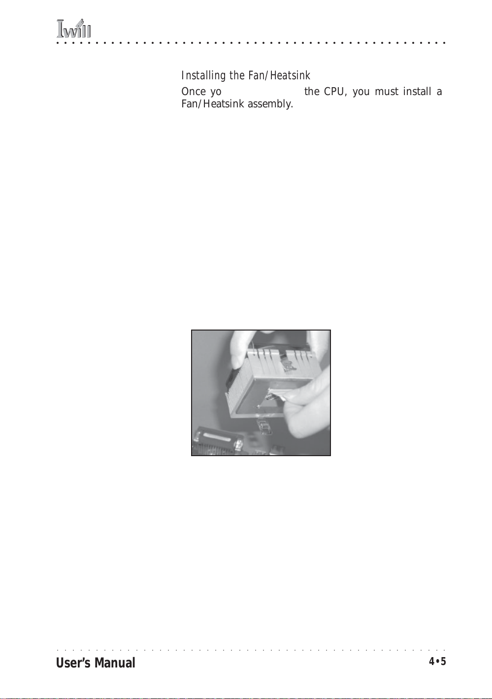
Installing the Fan/Heatsink
Once you have installed the CPU, you must install a
F an/Heatsink assembly. The Fan/Heatsink clips onto to
the CPU socket.
Prepare th e Heatsink
Before you install the Fan/Heatsink you must prepare
the F an/Heatsink assembly . The heatsink has a patch of
thermal interface material on the underside that is covered with protective tape or b y a plastic cover that covers the entire bottom of the heatsink. You must remove
the tape before you install the Fan/Heatsink assembly.
To remove the plastic cover, just pull it off. To remove
the tape do as follows:
1. Hold the free end of the tape at a 90° to the surface
of the heatsink. Pull the tape off with a smooth
quick movement that removes the tape only and
not the underlying thermal interface material.
Remove Protective Tape:
Remove the protective
tape covering the therm al
interface material on the
underside of the heatsink
by quickly pulling it off
pulling it off at an angle
of 90° to the heatsink.
Remove protective tape
from the Thermal
Interface Materi al
Next, install the processor Fan/Heatsink assembly as detailed below.
○○○○○○○○○○○○○○○○○○○○○○○○○○○○○○○○○○○○○○○○○○○○○○○○○○
User’s Manual
4•5

MPX2 Motherboard
○○○○○○○○○○○○○○○○○○○○○○○○○○○○○○○○○○○○○○○○○○○○○○○○○○
Install the Fan/Heatsink
To install the processor Fan/Heatsink assembly do as
follows:
1. Place the Fan/Heatsink on top of the CPU so that it
is sitting evenly on the pads on top of the CPU and
it does not contact the socket. The assembly retention clip mechanism should align with the corresponding lug extensions on the socket.
Step 1:
Place the Fan/Heatsink assembly on top of the CPU,
aligning the r etaining clip
mechanism to the m atching socket extensions.
Important:
Rest the heatsink evenly
Position the heatsink
evenly on the CPU so
that one edge hangs
over, but does not
contact the socket
on the pads on top of the
CPU so that the heatsink
is not in contact with the
socket.
2. Hold the Fan/Heatsink steady and press one end of
the retention clip down over the matching socket
lug extension so that the opening in the clip fits
over the lug securely and will not slip off.
Step 2:
Press one end of the retention clip over the
matching socket lug.
○○○○○○○○○○○○○○○○○○○○○○○○○○○○○○○○○○○○○○○○○○○○○○○○○○
4•6
Press the retention clip over
the socket lug with a flathead
screwdriver
Insert the tip in the slot in
the clip to hold it securely
User’s Manual

○○○○○○○○○○○○○○○○○○○○○○○○○○○○○○○○○○○○○○○○○○○○○○○○○○
4: Installing The Motherboard
3. Repeat the process on the opposite side . K eep hold-
ing the Fan/Heatsink steady. Press the end of the
retention clip over the corresponding lug extension
so that it snaps over the lug securely. Make sure the
Step 3:
Hold the Heatsink/Fan as-
Fan/Heatsink assembly is positioned directly over
the CPU and is not in contact with the socket.
sembly steady and press
the other retention clip
end over the other m atching lug extension so that
it clips on securely.
Connect Fan/Heatsink Power Lead
Plug the fan power lead onto the CPU F an po wer connector near the CPU socket. When you do this the CPU installation is complete.
Step 4:
Plug the Fan power lead
onto the CPU fan power
connector
Fan power lead plugs
onto the closest CPU
fan power connector.
If you are installing a dual CPU configuration, repeat this
procedure to install a second Athlon MP CPU in the second CPU socket.
○○○○○○○○○○○○○○○○○○○○○○○○○○○○○○○○○○○○○○○○○○○○○○○○○○
User’s Manual
4•7

MPX2 Motherboard
○○○○○○○○○○○○○○○○○○○○○○○○○○○○○○○○○○○○○○○○○○○○○○○○○○
Installing System Memory
This section details the procedure for installing system
memory on the motherboard. Correct memory configuration is critical for proper system operation. Please review this section carefully and follow the configuration
guidelines precisely.
Memory Specifications
Unbuffered Memory:
If you install unbuffered
DDR memory, the chipset
supports upto 2GB total
system memory only installed in the DIMM1 &
DIMM2 sockets.
The motherboard has four DIMM module sockets. This
motherboard uses DDR SDRAM DIMM modules for system memory. The system memory specifications are:
• PC1600 or PC2100 DDR SDRAM DIMM modules.
• Uses 64MB, 128MB, 256MB, 5 12MB or 1GB DIMMs .
• Maximum 2GB unbuffered and 3.5GB registered total system memory.
Memory Configuration Options
Registered Memory:
If you install registered
DDR memory, the chipset
supports upto 3.5GB total
system memory . If you install four 1GB modules,
the system will only recognize 3.5GB.
This motherboard has flexible memory configuration
options. Please note the following:
• Supports any mix of 64MB, 128MB, 256MB, 512MB
and 1GB modules.
• Any capacity DIMM may be used in any socket as
long as the total memory limit is not exceeded.
• Modules should be the same speed for best system
performance.
• Both unbuffered and and registered DDR SDRAM
are supported.
• Do not mix unbuffered and registered memory.
○○○○○○○○○○○○○○○○○○○○○○○○○○○○○○○○○○○○○○○○○○○○○○○○○○
4•8
User’s Manual

○○○○○○○○○○○○○○○○○○○○○○○○○○○○○○○○○○○○○○○○○○○○○○○○○○
4: Installing The Motherboard
Installing Memory Modules
Installing DIMM modules is simple. The modules insert
in the sockets and are held in place by the sock et retaining arms. The edge connectors on the modules are of
different widths and there are key notches in each module. These ensure that y ou can not insert a module incorrectly.
Before you install any modules, you should choose a
configuration. You should then prepare the requir ed number and type of DDR modules.
To install either type of module follow this procedure:
1. Align the module to the socket so that the edge
connectors on the module match the socket sections.
2. Hold the module perpendicular to the motherboard
and press the edge connector into the socket.
3. Press the module fully into the socket so that the
socket retaining arms swing up and engage the retention notches at each end of the module.
Follo wing the configuration y ou hav e chosen, repeat this
procedure if necessary so that all modules are installed.
Once the modules are installed, system memory installation is complete.
Module Installation:
Module retaining notch
Modules will only insert in
one orientati on. The width
of the two edge connector sections varies sli ghtly
Module retaining notch
and prevents in correct insertion.
Socket retaining arm
Socket retaining arm
○○○○○○○○○○○○○○○○○○○○○○○○○○○○○○○○○○○○○○○○○○○○○○○○○○
User’s Manual
4•9

MPX2 Motherboard
○○○○○○○○○○○○○○○○○○○○○○○○○○○○○○○○○○○○○○○○○○○○○○○○○○
Module Installation:
All modules insert in the
DIMM sockets in the same
way:
1. Align the mod ule to the
socket.
2. The socket retaining
arms should r otate up and
engage the module’s retaining notches as you
press it into the socket.
3. The retaining arm s must
engage for the module to
be properly installed.
PC1600 Memory Configuration
Only use PC1600 memory with a single CPU configuration where the CPU has a 200MHz Frontside Bus speed.
You must also set jumper JP5 to the 100MHz setting for
this configuration.
System Memory Recognition
The BIOS will automatically recognize the installed
memory configuration and configure the CMOS Setup
Utility. No other action is required to complete system
memory installation.
○○○○○○○○○○○○○○○○○○○○○○○○○○○○○○○○○○○○○○○○○○○○○○○○○○
4•10
User’s Manual

○○○○○○○○○○○○○○○○○○○○○○○○○○○○○○○○○○○○○○○○○○○○○○○○○○
4: Installing The Motherboard
Installing the Motherboard in a System Housing
This section explains the basic requirements for installing this motherboard in a system housing or “chassis”.
Since housing designs vary widely , y ou will need to consult the housing documentation for specific information.
This motherboard can be installed in any housing that
supports the EX-ATX form factor.
To install the motherboard in a system housing you will
need to do the following:
• Install a rear I/O panel shield
• Attach the board to the housing
• Connect leads from the housing’s front panel
You can then connect other internal system components
as described later in this chapter.
Motherboard Installation Procedure
This section assumes you are installing the board in a
suitable EX-ATX housing. We also assume y ou have prepared the board for installation as previously described
in this manual. If the housing you are using normally
stands vertically, place the open housing on it’s side before you start.
Please follow this procedure to install this motherboard:
1. Review any instructions that came with the system
housing and prepare the necessary mounting hardware that came with it.
2. Identify the mounting holes on the board and con-
firm that the housing has standoffs that match them.
3. Install the rear I/O panel shield that came with the
motherboard in the housing’s I/O panel opening.
This should fit in the housing.
○○○○○○○○○○○○○○○○○○○○○○○○○○○○○○○○○○○○○○○○○○○○○○○○○○
User’s Manual
4•11

MPX2 Motherboard
○○○○○○○○○○○○○○○○○○○○○○○○○○○○○○○○○○○○○○○○○○○○○○○○○○
4. Insert the board in the housing and align the mounting holes to the standoffs on the housing’s
motherboard mounting plate. Make sure all of the
rear I/O ports are properly aligned with the openings in the I/O panel shield.
5. Attach the board to the housing by inserting mounting screws in all the holes and tightening them
snugly.
Mounting Holes
There are 12 mounting
holes on the moth erboard
that should correspond to
mounting stan doffs on the
system housing’s motherboard mounting plate.
Required Tool:
• Philips-head screw d river
(Crosshead)
AMD-768
AMD
J24
Socket462
FDD(J23)
IDE2(J22)
IDE1(J21)
MPX2
J8
JP8
Secondary CPU
J13
Socket462
J11
J3
PCI1
PCI2
PCI3
PCI4
J5
PCI5
J6
PCI6
JP2
AGP PRO
+
J34A1
Primary CPU
JP5
JP3
DIMM1,2,3,4
J25
J30
J27
J26
J28
Mounting holes
○○○○○○○○○○○○○○○○○○○○○○○○○○○○○○○○○○○○○○○○○○○○○○○○○○
4•12
User’s Manual

○○○○○○○○○○○○○○○○○○○○○○○○○○○○○○○○○○○○○○○○○○○○○○○○○○
4: Installing The Motherboard
Connecting Front Panel Components
After the motherboard is installed in the system housing,
you should connect whatever front panel components
the housing has to the Front Panel feature connector on
the motherboard.
The figure below indicates the pin assignments of the
connector for your reference.
Front Panel Connector:
Leads from the fron t panel
features connect to this
header.
Power Connectors:
The power connectors are
for use with either an ATX
or EPS minimum 350W
power supply.
Please note that A TX connectors plug into only part
of the larger connectors,
as noted in the illustration. the motherboard
comes with stickers over
the unused section s. if you
will use an EPS power supply, remove the stickers.
Power On
System LED
IDE LEDACPI Reset
Front Panel feature connector
Speaker
Completing System Configuration
Once the motherboard is installed in the system housing,
you can proceed to connect or install whatever internal
devices you will use to complete the system. These will
at least include an AGP displa y car d and disk driv es and
connecting the housing power supply leads.
Cover sticker –
remove to use EPS
power supply
ATX connectors
plug into the
indicated
positions
Cover sticker –
remove to use EPS
power supply
24-pin EPS/ATX connector
(ATX uses 20 pins)
EPS/ATX 12V connector
(ATX uses 4 pins)
○○○○○○○○○○○○○○○○○○○○○○○○○○○○○○○○○○○○○○○○○○○○○○○○○○
User’s Manual
4•13
MPX2 Motherboard
○○○○○○○○○○○○○○○○○○○○○○○○○○○○○○○○○○○○○○○○○○○○○○○○○○
After that, having replaced the s ystem housing cover, you
can connect external peripherals to complete the pr ocess
of preparing the system for use. These will include at
least a video display monitor, a keyboard and a pointing
device such as a mouse. Please see the next chapter for
information on completing these final hardware installation steps and installing Operating System and support
software.
○○○○○○○○○○○○○○○○○○○○○○○○○○○○○○○○○○○○○○○○○○○○○○○○○○
4•14
User’s Manual

○○○○○○○○○○○○○○○○○○○○○○○○○○○○○○○○○○○○○○○○○○○○○○○○○○
5: System Configuration
In This Chapter:
Installing or Connecting Internal Peripherals
Installing an AGP Card
Connecting Internal Devices
Connecting External System Peripherals
Configuring the CMOS Setup Utility
Installing an OS & Support Software
5: System Configuration
This chapter explains what you need to do to assemble a
complete system after you ha ve installed the motherboard
in a system housing. This will include installing or connecting internal devices, connecting external s ystem components. Once the system is assembled, you’ll need to
check and possibly configure the motherboard’s CMOS
Setup Utility, install an Operating System and install the
support software supplied on the Power Installer support CD-ROM disc.
Installing or Connecting Internal Peripherals
To complete the assembly of a working system you will
need to at least install an AGP video display card and
connect whatever disk drives y ou will use in the sy stem.
This section covers what you need to know on the
motherboard side to do this. You will also need to consult the documentation that comes with your internal system peripherals for additional installation instructions and
information. This section covers the minimum components you will need to connect to the motherboard to
create a functioning system. You may plan to add other
devices as well.
○○○○○○○○○○○○○○○○○○○○○○○○○○○○○○○○○○○○○○○○○○○○○○○○○○
User’s Manual
5•1

MPX2 Motherboard
○○○○○○○○○○○○○○○○○○○○○○○○○○○○○○○○○○○○○○○○○○○○○○○○○○
Installing an AGP Card
The AGP connector on the board supports AGP 4X 1.5volt display cards . Follo w the instructions that come with
the display card for installing the card hardware in the
AGP slot.
AGP Configuration
Y ou can configure the amount of s ystem memory the A GP
card will use as auxiliary memory by adjusting the AGP
Aperture Size setting in the Advanced Chipset Features
section of the CMOS Setup Utility. The default aperture
setting is 64MB the maximum setting is 256MB, the minimum is 32MB.
Display Drivers
You should install the display card’s display driver software according to the instructions that come with the
card after you hav e completed system assembly and hav e
installed an OS and the support software for this
motherboard.
AGP Aperture Setting
You can set th e AGP aperture size in the Advanced
Chipset Features AGP &
P2P Bridge Con trol section
of the CMOS Setup Utility
○○○○○○○○○○○○○○○○○○○○○○○○○○○○○○○○○○○○○○○○○○○○○○○○○○
5•2
User’s Manual

○○○○○○○○○○○○○○○○○○○○○○○○○○○○○○○○○○○○○○○○○○○○○○○○○○
5: System Configuration
Connecting Internal Devices
To assemble a complete system capable of completing
the installation of this motherboard you will need to install and connect the following internal devices:
• Hard Disk Drive
• CD-ROM or other optical drive
• Floppy disk drive
The floppy disk drive is not strictly necessary, but is a
standard system component and is needed if you will
create driver floppy disks from the Power Installer 2.
We assume here, in the absence of an alternative drive
controller that any hard disk or optical driv es will be IDE
devices connected to the motherboard’s IDE channels.
Connecting IDE Devices
This motherboard supports two IDE channels, Primary
and Secondary . It has two IDE device connectors onboar d
which support IDE devices running in any data transfer
mode up to ATA-100. Each IDE connector supports two
drives, a Master and a Slave. The drives connect to the
motherboard with an IDE ribbon cable. IDE cables have
three connectors on them, one that plugs into a drive
connector on the board and the other two that connect to
IDE devices. The connector at the end of the cable is for
the Master drive. The connector in the middle of the cable
is for the Slave drive.
There are three types of IDE ribbon cable, supporting
transfer modes up through ATA-33, ATA-66 or ATA-100.
You must use a cable that supports the transfer mode of
the fastest device connected to it. F or example , if both an
A TA -66 mode and an A TA -1 00 mode device ar e connected
to the same cable, the cable must support ATA-100 mode
to achieve maximum performance.
To install an IDE drive, connect the drive to one of the
drive connectors on a suitable ribbon cable . Plug the board
end of the cable into one of the IDE connectors on the
motherboard.
○○○○○○○○○○○○○○○○○○○○○○○○○○○○○○○○○○○○○○○○○○○○○○○○○○
User’s Manual
5•3

MPX2 Motherboard
○○○○○○○○○○○○○○○○○○○○○○○○○○○○○○○○○○○○○○○○○○○○○○○○○○
IDE Drive Positioning
Normally the system’s primary hard disk drive should
be in the Primary Master position. If you will use only
the supplied ribbon cable, connect a CD-ROM drive to
the Primary Slave position.
If you obtain an additional IDE ribbon cable, you can
install a second hard disk drive in the Primary Slave position and install the CD-ROM as the Secondary Master.
This is a good idea if the CD-ROM drive uses a slower
data transfer mode than the hard disk drive.
Follo w any instructions that come with the drives to configure and install them. IDE devices generally can be set
to one of three operation modes:
• Master
• Slave
• Cable Select
Many drives come set to the Master setting. If you will
use the drive in a Slave position, y ou must r econfigur e it
as either Slave or use the Cable Select setting to allow the
drives position on the cable to define the mode, if the
drives support that mode.
Connecting a Floppy Disk Drive
This motherboard has one Floppy Drive connector for
connecting one or two floppy disk drives . Most computer
systems use one 3.5-inch 1.44MB floppy disk drive. The
drive connector is for a standard floppy drive ribbon cable .
To install a floppy disk drive, connect the drive to the
end of the cable, which is the Drive A: position. Plug the
other end of the cable into the floppy disk drive connector on the motherboard.
○○○○○○○○○○○○○○○○○○○○○○○○○○○○○○○○○○○○○○○○○○○○○○○○○○
5•4
User’s Manual

○○○○○○○○○○○○○○○○○○○○○○○○○○○○○○○○○○○○○○○○○○○○○○○○○○
5: System Configuration
Onboard IDE Connectors
Each channel connector
supports one IDE channel
J8
JP8
Primary CPU
J24
J27
with two drives, a Master
and a Slave. The Master
drive connects to the connector on the end of the
J13
Secondary CPU
Socket462
Socket462
ribbon cable. The Slave
drive connects to the con-
J11
nector in the middle of
the ribbon cable.
Note:
The ribbon cable used
must support the transfer
mode of the f astest device
connected to it to avoid
degraded perf orman ce.
J3
PCI1
PCI2
PCI3
PCI4
J5
PCI5
J6
PCI6
JP2
AGP PRO
+
J34A1
DIMM1,2,3,4
JP5
AMD-768
AMD
JP3
MPX2
FDD(J23)
IDE2(J22)
IDE1(J21)
J25
J26
J30
J28
Floppy Drive Connector
The floppy drive connector supports two floppy
disk drives. The first drive ,
Drive A:, connects to the
connector on the end of
the floppy drive connector cable. A second drive,
Drive B:, would connect to
the middle connector on
the cable although systems now commonly only
have one floppy disk drive .
IDE2 Secondary Channel
Floppy connector
IDE1 Primary Channel
○○○○○○○○○○○○○○○○○○○○○○○○○○○○○○○○○○○○○○○○○○○○○○○○○○
User’s Manual
5•5

MPX2 Motherboard
○○○○○○○○○○○○○○○○○○○○○○○○○○○○○○○○○○○○○○○○○○○○○○○○○○
Connecting External System Peripherals
To complete the assembly of functioning system you will
need at minimum to connect the following external system components to the system housing:
• Video Display Monitor
• Keyboard
• Mouse or other Pointing Device
Connecting a Display Monitor
You can connect any display monitor supported by the
AGP display card you installed in the system. This may
include either a CRT or LCD monitor, depending on the
card’s specifications.
Connect the display monitor cable to the appropriate display connector on the A GP card accor ding to the instructions that come with the card and monitor.
Connecting a Keyboard & Mouse
You can use either PS/2 or USB input devices with this
motherboard.
Connecting PS/2 Devices
Connect a PS/2 keyboard and mouse to the Keyboard
and Mouse PS/2 ports on the rear I/O port panel. Don’t
connect or disconnect a device while the system is turned
on. Doing so can damage the board.
Connecting USB Devices
You can use a USB keyboard and mouse with this
motherboard. They plug into two of the USB ports. The
Operating System you use must support USB to use any
USB devices. You can plug and unplug USB devices when
the system is turned on.
○○○○○○○○○○○○○○○○○○○○○○○○○○○○○○○○○○○○○○○○○○○○○○○○○○
5•6
User’s Manual
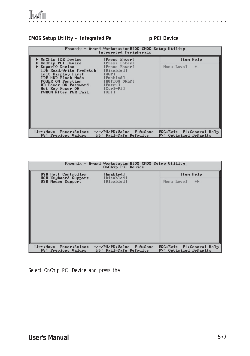
○○○○○○○○○○○○○○○○○○○○○○○○○○○○○○○○○○○○○○○○○○○○○○○○○○
5: System Configuration
CMOS Setup Utility – Integrated Peripherals: OnChip PCI Device
Integrated Peripherals: OnChip PCI Device
Select OnChip PCI Device and press the Enter key to bring up the
OnChip PCI Device screen. The “USB K eyboard Support” and “USB Mouse
Support” defaults are Disabled. If you want to use a USB keyboard or
pointing device, set the approrpiate item to the Enabled setting. The
keyboard setting allows you to use a U SB keyboar d befor e th e operating system loads. Your OS must also support USB to use a USB keyboard with it.
○○○○○○○○○○○○○○○○○○○○○○○○○○○○○○○○○○○○○○○○○○○○○○○○○○
User’s Manual
5•7

MPX2 Motherboard
○○○○○○○○○○○○○○○○○○○○○○○○○○○○○○○○○○○○○○○○○○○○○○○○○○
Configuring the CMOS Setup Utility
The motherboard Award BIOS includes the CMOS Setup
Utility that creates a system configuration record that is
stored in CMOS memory on the board and is requir ed by
the system to operate properly.
Most of the configuration settings are either predefined
by the BIOS Optimized Default settings which are stored
with the BIOS or are automatically detected and configured without requiring User action. There are a few settings that you may need to change depending on your
system configuration.
This section gives a brief profiles of the several sections
of the CMOS Setup Utility and indicates settings you might
need to change and those which you should not.
The CMOS Setup Utility User Interface
The CMOS Setup Utility user interface is simple and largely
self evident. The utility can only be operated from the
keyboard and all commands are keyboard commands.
The utility does not support mouse use. The commands
are straightforward and those available for the program
section you are in are listed at the bottom of the screen.
The main screen has few commands, other sections hav e
more. Gener al Help, which lists the commands and their
functions is available at any time b y pr essing the F1 k ey.
Running the CMOS Setup Utility
The CMOS Setup Utility does not require an operating
system to run. You run the utility by typing the Del or
Delete key when the computer is starting to boot up. The
utility’s main screen will then appear.
○○○○○○○○○○○○○○○○○○○○○○○○○○○○○○○○○○○○○○○○○○○○○○○○○○
5•8
User’s Manual

○○○○○○○○○○○○○○○○○○○○○○○○○○○○○○○○○○○○○○○○○○○○○○○○○○
5: System Configuration
CMOS Setup Utility – Interface commands
○○○○○○○○○○○○○○○○○○○○○○○○○○○○○○○○○○○○○○○○○○○○○○○○○○
User’s Manual
5•9

MPX2 Motherboard
○○○○○○○○○○○○○○○○○○○○○○○○○○○○○○○○○○○○○○○○○○○○○○○○○○
CMOS Setup Utility Program Sections
The CMOS Setup Utility is divided into several subsections and some top level commands including the following sections:
• Standard CMOS Features
• Advanced BIOS Features
• Advanced Chipset features
• Integrated Peripherals
• Power Management Setup
• PnP/PCI Configurations
• PC Health Status
• IWILL Smart Setting
The main screen also has these command options:
• Load Fail-Safe Defaults
• Load Optimized Defaults
• Set Supervisor Password
• Set User Password
• Save & Exit Setup
• Exit Without Saving
Please see the following sections for a brief profile of
what each section does, information on settings you
might want to change and things to leave alone.
To open one of the program sections, highlight the item
you want and press the Enter key. To change a setting,
highlight an item and use the “Value” keys indicated to
change the setting. Alternatively, press the Enter key
and all options for that item will display and you can
choose from those listed.
○○○○○○○○○○○○○○○○○○○○○○○○○○○○○○○○○○○○○○○○○○○○○○○○○○
5•10
User’s Manual

○○○○○○○○○○○○○○○○○○○○○○○○○○○○○○○○○○○○○○○○○○○○○○○○○○
5: System Configuration
CMOS Setup Utility – Main Screen
○○○○○○○○○○○○○○○○○○○○○○○○○○○○○○○○○○○○○○○○○○○○○○○○○○
User’s Manual
5•11

MPX2 Motherboard
○○○○○○○○○○○○○○○○○○○○○○○○○○○○○○○○○○○○○○○○○○○○○○○○○○
Standard CMOS Features
Main Section Functions
This section has the real time clock settings, the IDE and
floppy device settings.
Default & Autodetected Settings
The IDE device settings are autodetected. You shouldn’t
need to change this. The floppy and other settings are
standard defaults.
Setting Options & Constraints
You can reset the time and date settings if they are not
correct for your location.
CMOS Setup Utility – Standard CMOS Features
Note:
In operation, the screen
will display the detected
IDE devices
○○○○○○○○○○○○○○○○○○○○○○○○○○○○○○○○○○○○○○○○○○○○○○○○○○
5•12
User’s Manual

○○○○○○○○○○○○○○○○○○○○○○○○○○○○○○○○○○○○○○○○○○○○○○○○○○
5: System Configuration
Advanced BIOS Features
Main Section Functions
This section mainly configures boot options including
boot devices and their boot order and some power functions. There are also some miscellaneous boot configur ation settings.
Default & Autodetected Settings
The screen illustration shows the default settings. These
do not need to be changed. You can customize the settings to suit your purposes if necessary and you know
what you’re doing.
Setting Options & Constraints
You can change the boot device assignments and order,
the boot options and the power on settings as you like.
You can select which security option applies, Setup or
System. You must set a password for it at the main level
or it will have not effect.
CMOS Setup Utility – Advanced BIOS Features
○○○○○○○○○○○○○○○○○○○○○○○○○○○○○○○○○○○○○○○○○○○○○○○○○○
User’s Manual
5•13

MPX2 Motherboard
○○○○○○○○○○○○○○○○○○○○○○○○○○○○○○○○○○○○○○○○○○○○○○○○○○
Advanced Chipset Features
Main Section Functions
Configures the chipset, BIOS caching and the A GP Aperture size.
Default & Autodetected Settings
Everything on this screen is an optimized default or is
autodetected.
Setting Options & Constraints
Don’t change the autodetected DRAM settings in the
Advanced DRAM Control subsection unless you know
what you are doing. Incorrect settings can cause system
instability or result in the system not working.
You can the AGP settings in the AGP & P2P Bridge Control subsection. The default mode is 4X. Change it to 1X/
2X if your display card isn’t a 4X card.
Don’t change the Cacheable settings.
Don’t chnage the Memory Hole setting.
Leave the two Throttling settings as they are.
CMOS Setup Utility – Advanced Chipset Features
○○○○○○○○○○○○○○○○○○○○○○○○○○○○○○○○○○○○○○○○○○○○○○○○○○
5•14
User’s Manual

○○○○○○○○○○○○○○○○○○○○○○○○○○○○○○○○○○○○○○○○○○○○○○○○○○
5: System Configuration
Integrated Peripherals
Main Section Functions
Configures the peripheral features integrated onto the
motherboard.
Default & Autodetected Settings
Everything on this screen is an optimized default. IDE
transfer mode settings are autodetected. The settings in
the SuperIO Device subsection are standard PC settings.
Setting Options & Constraints
You can disable the onboard IDE channels in the OnChip
IDE Device subsection and manually configured transfer
modes if necessary.
You can change USB settings in the OnChip PCI Device
subsection including enabling the use of a USB keyboard
and mouse.
The SuperIO Device subsection configures serial parallel
and IR ports and enables the Floppy Disk Drive controller . You can change these settings as needed. Set the P arallel Port mode according to the mode supported b y your
printer. If you install an IR port module, you have to set
the UART Mode Select line to the appropriate IR setting.
Most newer ATA (IDE) hard disk drives will support the
enabled IDE HDD Block Mode. Disable this if any drive
you will use doesn’t support this mode.
The last four items control how the power on function
works. If you set the Keyboard Power On jumper J8 to
Enabled, you can use the alternate Power On features.
CMOS Setup Utility – Integrated Peripherals
○○○○○○○○○○○○○○○○○○○○○○○○○○○○○○○○○○○○○○○○○○○○○○○○○○
User’s Manual
5•15

MPX2 Motherboard
○○○○○○○○○○○○○○○○○○○○○○○○○○○○○○○○○○○○○○○○○○○○○○○○○○
Power Management Setup
Main Section Functions
Configures power management settings. These are overridden by ACPI power management in Windows when
ACPI Function is set to the default, Enabled.
Default & Autodetected Settings
Everything on this screen is an optimized default.
Setting Options & Constraints
You can set a variety of Wake Up events in the WakeUp
Event subsection. These include setting a date and time
for the system to turn on or wake up from a Suspend
state and several other wake up features.
The Reload Global timer subsection lets you set what
hardware events will trigger a reset of the power management timer which determines system timeouts. By default all items in the subsection are set to Disabled.
For the P ow er Management line you can select Minimum
or Maximum configurations rather than the User Defined
defaults. You can customize all settings in User Defined
mode. If your OS supports power management, configure it there.
The Soft-Off by PBTN line sets what happens when you
push the system housing power button. The default is
Instant-Off which turns of the system immediately. The
alternate setting is Delay 4 Sec, which requires pushing
the button for four seconds befoe the system turns off.
CMOS Setup Utility – Power Management Setup
○○○○○○○○○○○○○○○○○○○○○○○○○○○○○○○○○○○○○○○○○○○○○○○○○○
5•16
User’s Manual

○○○○○○○○○○○○○○○○○○○○○○○○○○○○○○○○○○○○○○○○○○○○○○○○○○
5: System Configuration
PnP/PCI Configurations
Section Function
Configures Plug and Play and other PCI bus settings.
Default & Autodetected Settings
The default is for the BIOS to control these functions.
Setting Options & Constraints
Don’t change the resource settings, they’re set to be
handled automatically by the BIOS. If you have a problem after you install an expansion card, set Reset Configuration Data to Enabled to rewrite the ESCD. You can
set them manually by setting the Resources Controlled
By line to the Manual setting.
Normally you should leave the PCI/VGA Palette Snoop
feature disabled unless you have a PCI display card installed and it has a display problem at startup.
CMOS Setup Utility – PnP/PCI Configurations
○○○○○○○○○○○○○○○○○○○○○○○○○○○○○○○○○○○○○○○○○○○○○○○○○○
User’s Manual
5•17

MPX2 Motherboard
○○○○○○○○○○○○○○○○○○○○○○○○○○○○○○○○○○○○○○○○○○○○○○○○○○
PC Health Status
Section Function
Configures the Shutdown Temperature and displays detected system information including CPU temperature,
cooling fan status, CPU Vcore voltage and various other
voltage levels.
Default & Autodetected Settings
The CPU Shutdown Temperature setting is an optimized
default. The list of system information is autodetected
and displayed.
Setting Options & Constraints
You can select a CPU Shutdown Temperature setting. If
the detected CPU temperature reaches that point, the s ystem will automatically shut down to protect the CPU.
CMOS Setup Utility – PC Health Status
Note:
The screen illustration
does not display the detected information you
will see on a live screen.
○○○○○○○○○○○○○○○○○○○○○○○○○○○○○○○○○○○○○○○○○○○○○○○○○○
5•18
User’s Manual

○○○○○○○○○○○○○○○○○○○○○○○○○○○○○○○○○○○○○○○○○○○○○○○○○○
5: System Configuration
IWILL Smart Setting
Section Function
Configures CPU settings.
Default & Autodetected Settings
The default is to autodetect CPU settings.
Clock Ratio Setting:
You m ust set the CPU Clock
Ratio setting manu ally for
Athlon MP CPUS. The ratio settings are as f ollows:
MP 1500+: x10
MP 1600+: x10.5
MP 1700+: x11
MP 1800+: x11.5
MP 1900+: x12
MP 2000+: x12.5
Setting Options & Constraints
Don’t change the “Spread Spectrum” setting.
Don’t change the auto-detected settings unless you really
know what you are doing. You can use the three CPU
items to configure the CPU settings yourself, but we do
not recommend this. Configuring CPU settings at variance with AMD’s specifications may damage the CPU
and void the warranty. See the section on Overclocking
in Chapter 6 for more information.
Set the Aux FAN item to ON if you want to connect additional system cooling fans to the AUX fan connectors on
the motherboard.
CMOS Setup Utility – IWILL Smart Setting
○○○○○○○○○○○○○○○○○○○○○○○○○○○○○○○○○○○○○○○○○○○○○○○○○○
User’s Manual
5•19

MPX2 Motherboard
○○○○○○○○○○○○○○○○○○○○○○○○○○○○○○○○○○○○○○○○○○○○○○○○○○
Load Fail-Safe Defaults
This loads a set of minimum configuration defaults. It is
used to allow the system to start and then troubleshoot
hardware problems. You shouldn’t need to use this, it’s
mainly for technicians.
Load Optimized Defaults
This loads the Optimized Defaults. Do this if the configuration record has been corrupted or mistakenly configured or after the Clear CMOS procedure has been performed. See Chapter 3 for more information on this procedure. To load the defaults, select this item, press the
Enter key, type a Y and press Enter again.
○○○○○○○○○○○○○○○○○○○○○○○○○○○○○○○○○○○○○○○○○○○○○○○○○○
5•20
User’s Manual

○○○○○○○○○○○○○○○○○○○○○○○○○○○○○○○○○○○○○○○○○○○○○○○○○○
5: System Configuration
Set Supervisor/User Password
These two items set passwords for system access.
Setting a Password
You can install a Supervisor or User Passwor d. The password prevents access to the CMOS Setup Utility (Supervisor) or the entire system (User).
To install a password, follow these steps:
1. Highlight either Set Passw ord item in the main menu
and press Enter.
2. The password dialog box will appear.
3. If you are entering a new password, carefully type
in the password. You cannot use more than eight
characters or numbers. Passwords are case-sensitive. Press Enter after you have typed in the password. If you ar e deleting a passw or d that is already
installed just press Enter when the password dialog
box appears.
4. The system will ask you to confirm the new pass-
word by asking y ou to type it in a second time. Car efully type the password again and press Enter, or
just press Enter if you are deleting a password that
is already installed.
5. If you have used the correct format, the password
will be installed.
If you decide not to set a password after bringing up the
password entry window, press the Enter key, not Esc to
exit the password entry window.
○○○○○○○○○○○○○○○○○○○○○○○○○○○○○○○○○○○○○○○○○○○○○○○○○○
User’s Manual
5•21

MPX2 Motherboard
○○○○○○○○○○○○○○○○○○○○○○○○○○○○○○○○○○○○○○○○○○○○○○○○○○
Save & Exit Setup
This saves the current utility configur ation as a new configuration record, e xits the utility and r estarts the sy stem
using the saved configuration record.
Exit Without Saving
Exits the utility and restarts the system without changing
the saved configuration record.
In general, it should not be necessary to use the CMOS
Setup Utility once you have fully configured it. In the
event you do need to change or re-establish the settings,
always make sure to save the settings when you exit the
utility or the new settings will not be stored.
○○○○○○○○○○○○○○○○○○○○○○○○○○○○○○○○○○○○○○○○○○○○○○○○○○
5•22
User’s Manual

○○○○○○○○○○○○○○○○○○○○○○○○○○○○○○○○○○○○○○○○○○○○○○○○○○
5: System Configuration
Installing an OS & Support Software
This section covers installing Operating System softw are
and the support software on the Power Installer support
CD-ROM disc. Once y ou have configured the CMOS Setup
Utility, you should install an OS. If you install a supported Microsoft OS, you should also install the driver
software on the Power Installer disc.
Installing an Operating System
This motherboard can use the following Operating Systems:
• Microsoft Windows 9X
• Microsoft Windows NT
• Microsoft Windows 2000
• Microsoft Windows XP
• Linux (Kernel 2.x.x or later)
• Novell Netware 5.0 or later
• Solaris 7.0 or later
Prepare the hard disk drive and install an OS according
to the instructions that come with the OS you will use.
Installing the Support Software
The Power Installer CD-ROM disc comes with required
hardware driv er s for Microsoft Windo w s and some additional utility software , as noted in Chapter 2. If y ou ha v e
installed a supported Microsoft OS, you must install the
required drivers. If you have installed Linux, you can
create Linux support disks.
○○○○○○○○○○○○○○○○○○○○○○○○○○○○○○○○○○○○○○○○○○○○○○○○○○
User’s Manual
5•23

MPX2 Motherboard
○○○○○○○○○○○○○○○○○○○○○○○○○○○○○○○○○○○○○○○○○○○○○○○○○○
Installing Windows Drivers
This section assumes you have installed one of the supported Microsoft Operating Systems on the system hard
disk drive.
To install Windows drivers, insert the Power Installer
support CD-ROM disc in the system’s CD-ROM (or other
optical drive) and wait for the Power Installer interface
to automatically load. If it doesn’t start, run the Power
Installer interface directly from the disc by running Setup.
The Power Installer main screen will appear. Click on
this motherboard’s model number to open the section
for this board.
Power Installer:
Main Screen
Click on the model name
for this board in the
Socket A section.
○○○○○○○○○○○○○○○○○○○○○○○○○○○○○○○○○○○○○○○○○○○○○○○○○○
5•24
User’s Manual

○○○○○○○○○○○○○○○○○○○○○○○○○○○○○○○○○○○○○○○○○○○○○○○○○○
5: System Configuration
The main screen will appear with the items for this
motherboard listed. Click on Driver Intsllation to install
the AMD Driver Pack first.
Power Installer:
MPX2 Main Screen
You should install the required AMD driver pack
first from the Driver installation section.
Power Installer:
Driver Installation
Click on Service Pack
Driver to run the AMD
Driver Pack installation
program.
The Driver Installation screen will appear. Click on “Service Pack Driver” to run the AMD Driver Pack installation program.
User Manual
This item simply directs you to look on the IWILL web
site – www .iwill.net – to get a copy of this User’s Manual
in Adobe Acrobat PDF format.
○○○○○○○○○○○○○○○○○○○○○○○○○○○○○○○○○○○○○○○○○○○○○○○○○○
User’s Manual
5•25

MPX2 Motherboard
○○○○○○○○○○○○○○○○○○○○○○○○○○○○○○○○○○○○○○○○○○○○○○○○○○
Installing the Utility Software
To install the utility software bundled on the Power Installer disc, click on Software Utility in the main screen
to open the Software Utility window.
To install the the supplied utility software packages, click
on the item you want to install and follow the install
program’s instructions.
Power Installer:
Software Utility Section
and follow the in stall program instructions.
The Make Driver Utility
The “Make Driver” utility makes driver floppy disks.
There aren’t any disks you need for this board in the
program list, so you don’t need to use this program.
Making a Linux Support Disk
You can boot the system from the Power Installer disc.
The system will boot from a Linux k ernel on the disc and
you can use the disk creator that loads to create a Linux
support disk. You can then use it to install any necessary
modules according to your Linux distribution’s instructions for module installation.
○○○○○○○○○○○○○○○○○○○○○○○○○○○○○○○○○○○○○○○○○○○○○○○○○○
5•26
User’s Manual

○○○○○○○○○○○○○○○○○○○○○○○○○○○○○○○○○○○○○○○○○○○○○○○○○○
6: Using The Motherboard
In This Chapter:
Using System Features
Front Panel Controls & Indicators
Additional System Features
Installing & Configuring An IR Port
Performance Optimization
Troublesh ooting
6: Using the Motherboard
This chapter covers several topics related to using this
motherboard once it is installed in a working system.
These include external system features that connect to
the motherboard, things you can do to optimize the performance of a system based on this board and some
troubleshooting tips you can revie w in the event any pr oblems arise.
Using System Features
This section explains the system controls and indicators
that connect to the motherboard. It also explains how
the other system level features on the board work.
Front Panel System Controls & Indicators
The front panel of the system housing will ha v e some or
all of the front panel features that connect to the
motherboard. These enable the User to determine some
information on the systems operational status and provide some system controls.
System Controls
The front panel connector on the motherboard supports
several system controls that mount on the front panel of
the system housing.
○○○○○○○○○○○○○○○○○○○○○○○○○○○○○○○○○○○○○○○○○○○○○○○○○○
User’s Manual
6•1

MPX2 Motherboard
○○○○○○○○○○○○○○○○○○○○○○○○○○○○○○○○○○○○○○○○○○○○○○○○○○
Power Button
Function: Turns the system On and Off.
Use: This button is configured by the CMOS Setup Utility
by the “Soft-Off by PB TN” line in the Pow er Management
section. Depending on the setting, the power button will
function in one of two modes, instant on/off or instant
on/4 second delay off. In the delay mode , when you push
the power button for less than 4 seconds when the system is turned on, the system goes into the Suspend pow er
conservation mode. In this configuration, you have to
push the power button for more than 4 seconds to turn
the system power off.
Reset Switch
Function: Restarts the system to cold boot.
Use: Press the button to restart the system. This forces a
restart under all conditions. Don’t use the R eset button if
you can shut the system do wn from within the Operating
System.
Note On Reset & Rebooting:
You should always restart or shut down the system by
using the OS command for this. This procedure allows
the OS to shut down properly, minimizing the possibility
of hard disk drive problems or data loss. If the system
crashes or “hangs”, you may have to restart the system
at the hardware level. There are two hardware reboot
options, a keyboard command and the Reset button.
You can effect a “warm” reboot with a key command if
the OS supports it. For e x ample , all ver sions of Micr osoft
Windows support restarting the computer with the CtrlAlt-Del (Delete) command. You can try this command
first if it is supported. Otherwise, you will need to use
the Reset button.
Suspend Button
Function: Toggles system in and out of Suspend mode.
Use: Press the button to cause the system to enter or
resume from Suspend mode.
Note: The front panel feature connector supports a sys-
tem Suspend button (the ACPI connector) but not all s ystem housings have this button. The same function can
be performed at the Operating System lev el if the OS supports the feature.
○○○○○○○○○○○○○○○○○○○○○○○○○○○○○○○○○○○○○○○○○○○○○○○○○○
6•2
User’s Manual

○○○○○○○○○○○○○○○○○○○○○○○○○○○○○○○○○○○○○○○○○○○○○○○○○○
6: Using The Motherboard
Indicator LEDs
The motherboard front panel features connector supports
three system status indicator LEDs:
• Power Status LED Indicator
Lights when the system is turned on.
• Hard Disk Drive Activity LED Indicator
Flashes during hard disk drive access.
• Power Conservation Mode LED Indicator
Lights to indicate the system is in a Suspend state
power conservation mode.
Most system housings will hav e all of these LEDs mounted
in the housing’s front panel.
Wake Up Featur es
There are two system wake up features, Wake On LAN
and W ake On Ring. These ar e set to Diabled by default in
the W ak eUp Event Control subsection of the P ow er Management section of the CMOS Setup Utility . You must set
the RI Event/WOL line to Enabled to use these features.
Wake On LAN (WOL)
Function: The system wakes up in response to a signal
arriving over a LAN that it is connected to.
Use: The onboard WOL connector supports connection
to a PCI Network Interface Card. The WOL cable from
the card connects to the WOL connector on the board.
Wake On Ring(WOR)
Function: The system wakes up in response to a “ring
in” signal from a telephone line an internal modem is
connected to.
Use: The onboard WOR connector supports connection
to an internal PCI modem card. The W OR cable from the
modem card connects to the W OR connector on the board.
○○○○○○○○○○○○○○○○○○○○○○○○○○○○○○○○○○○○○○○○○○○○○○○○○○
User’s Manual
6•3

MPX2 Motherboard
○○○○○○○○○○○○○○○○○○○○○○○○○○○○○○○○○○○○○○○○○○○○○○○○○○
Installing & Configuring An IR Port
There is a pin header connector for an Infrared communications port module on the motherboard. An IR port
enable wireless communication between the sy stem and
another device with IR capability. Common examples of
such devices are a PD A or notebook computer. Installing
an IR port module requires disabling the COM2 serial
port on the rear I/O panel and reconfiguring it for IR use
in the CMOS Setup Utility.
Installing an IR port module requires an expansion slot
opening unless the system housing has a built-in IR port
with a cable to connect to the motherboard.
Follo w the instructions that come that come with the port
module you want to install. The basic installation procedure is as follows if the module installs in an expansion
slot opening:
1. Turn off and unplug the system if necessary.
2. Remove the system housing cover.
3. Locate the JP2 IR pin header connector on the
motherboard. It is below the lowest PCI slot.
4. Remove the e xpansion slot cover in the system housing that corresponds to the PCI slot. There may be a
slot cover retaining screw to remove and put aside
for later use.
5. Insert the port module in the expansion slot access
opening and align the module’s mounting bracket
with the screw hole for the retaining scre w (if ther e
is one). Insert the screw and tighten it to secure the
port module in place.
6. Plug the module’s connector cable onto the IR connector on the motherboard.
7. Replace the system housing cover.
8. Plug in and turn on the computer.
9. Run the CMOS Setup Utility and pen the Integrated
Peripherals section. Set the “UART Mode Select” to
the required mode, IrDA or ASKIR, and configure
the port settings below it if necessary. Save the settings and reboot.
○○○○○○○○○○○○○○○○○○○○○○○○○○○○○○○○○○○○○○○○○○○○○○○○○○
6•4
User’s Manual

○○○○○○○○○○○○○○○○○○○○○○○○○○○○○○○○○○○○○○○○○○○○○○○○○○
6: Using The Motherboard
CMOS Setup Utility – Integrated Peripherals – SuperIO Device
UART Mode Select – IR mode selection for COM2
The supported Microsoft Operating Systems should automatically detect and configure the port module after
you restart the sy stem. Consult the OS documentation or
online Help for more information if necessary. You may
also need to install support software that came with the
IR port module in order to use it. Consult the installation
instructions that came with the module for additional
instructions.
○○○○○○○○○○○○○○○○○○○○○○○○○○○○○○○○○○○○○○○○○○○○○○○○○○
User’s Manual
6•5

MPX2 Motherboard
○○○○○○○○○○○○○○○○○○○○○○○○○○○○○○○○○○○○○○○○○○○○○○○○○○
Performance Optimization
This section covers things you can do to increase the
performance of a system based on this motherboard. The
topics covered include system memory, disk subsystems
and processor upgrades or adjustments.
System Memory
Adding sy stem memory will increase system performance
Warning:
Do not install a mix of
PC1600 and PC2100 DDR
DIMMs.
and capability under any of the supported Operating System. This motherboard supports a total of 2GB of unbuffered DDR memory (in DIMM1 & DIMM2 only) or 3.5GB
of registered DDR memory in all sockets . If y ou ha ve not
installed the maximum, you can consider increasing the
amount of installed system memory. Additional system
memory speeds up system operation and in some cases
produces additional stability in the Operating System.
Disk Subsystems
This motherboard supports IDE drives using data transfer modes up through ATA-100. If you use IDE drives as
the primary disk subsystem, selecting drives that support ATA-100 and have a high rotation speed (at least
7,200rpm) will maximize performance.
If you need even better performance from a disk subsystem, you can consider adding a SCSI controller card
and SCSI disk drive. A SCSI disk controller with highspeed SCSI hard disk drives will provide a substantial
performance enhancement.
Processor Upgrades & Adjustments
Processor speed has a significant effect on over all system
performance. To increase system performance, you can
consider using or upgrading to a faster processor.
The AMD Athlon processors used by this motherboard
come in a variety of clock speeds. To maximize performance, select a processor with the fastest clock speed
the system budget or specification allows.
○○○○○○○○○○○○○○○○○○○○○○○○○○○○○○○○○○○○○○○○○○○○○○○○○○
6•6
User’s Manual

○○○○○○○○○○○○○○○○○○○○○○○○○○○○○○○○○○○○○○○○○○○○○○○○○○
6: Using The Motherboard
You can install a duall CPU configuration on this
motherboard using Athlon MP CPUs. This will significantly increase system performance with Operating Systems that support SMP (Symetrical Multiprocessing), such
as Microsoft Windows XP, Linux or FreeBSD.
The CMOS Setup Utility’s IWILL Smart Setting feature
will automatically detect and configure whatever pr ocessors are installed. Manual configuration settings are also
available, but setting the processor to operating parameters outside those specified by AMD can damage the
CPU and void the warranty.
Overclocking
It is possible to adjust the CPU configuration beyond r ated
parameters using the IWILL Smart Setting section of the
CMOS Setup Utility . This procedure is commonly referr ed
to as “overclocking” the CPU. While it is possible to
overclock the CPU on this motherboard, IWILL does not
assure reliable system performance if you do so and doing this may violate your CPU warr anty. Improperly configured, overclocking can shorten the life of the CPU or
even cause damage to the CPU, the motherboard, or both
and possibly damage other components as well. If you
are going to over clock the CPU, please make certain you
know what you are doing.
There are three items in the IWILL Smart Setting section
that configure the CPU clock:
• CPU Clock
Sets the CPU external clock speed. The default is
133MHz. The setting is adjustable from 100MHz to
250MHz.
• CPU Clock Ratio
Sets the multiplier for the CPU Clock. The Auto setting detects the CPU’s rated multiplier. Manual settings range from x 5 to x 15.
• CPU Vcore Setting
Sets the CPU’s core voltage. The Auto setting detects the CPU’s rated voltage . Manual settings r ange
from 1.125V to 1.850V.
To adjust a setting, you highlight the item and press the
Enter key to bring up the setting options window. These
settings affect both CPUs in a dual CPU configuration.
○○○○○○○○○○○○○○○○○○○○○○○○○○○○○○○○○○○○○○○○○○○○○○○○○○
User’s Manual
6•7

MPX2 Motherboard
○○○○○○○○○○○○○○○○○○○○○○○○○○○○○○○○○○○○○○○○○○○○○○○○○○
CMOS Setup Utility – IWILL Smart Setting
CPU Configuration Options
○○○○○○○○○○○○○○○○○○○○○○○○○○○○○○○○○○○○○○○○○○○○○○○○○○
6•8
User’s Manual

○○○○○○○○○○○○○○○○○○○○○○○○○○○○○○○○○○○○○○○○○○○○○○○○○○
6: Using The Motherboard
Troubleshooting
This section details some things you can do to evaluate
problems that could possibly occur in the course of using this motherboard. The topics covered include possible hardware problems and problems with the CMOS
Setup Utility’s system configuration record.
Hardware Problems
A hardware problem may occur either after you install
additional hardware or because some e xisting har dw ar e
has failed or has a disconnected or loose connection.
This section has some pointers on things you can check
before seeking assistance.
General Hardware Troubleshooting
If the motherboard does not operate properly when you
first try to use it in the system, it is likely that it is either
configured incorrectly, there are problems with external
connections. It os also possible the board or some other
system component is defective. Always check the most
obvious possibilities first.
First check the external components:
• Make sure the system, the monitor and any other
external peripherals are plugged in and turned on.
Confirm that the system and the power LEDs on
any external peripherals are on.
• Check that the monitor, keyboard and mouse are
properly connected.
Next check the CMOS Setup Utility:
• Run the CMOS Setup Utility and load the Optimized
Defaults. Reset any other custom settings. Remember to “Save & Exit Setup” to restart the computer.
○○○○○○○○○○○○○○○○○○○○○○○○○○○○○○○○○○○○○○○○○○○○○○○○○○
User’s Manual
6•9

MPX2 Motherboard
○○○○○○○○○○○○○○○○○○○○○○○○○○○○○○○○○○○○○○○○○○○○○○○○○○
If there is still a problem, check the internal components.
Turn off and unplug the system before you remove the
system housing cover.
• Press all installed DIMMs into the module sockets
to make sure they’re fully inserted.
• Make sure you used the correct cables to connect
the internal peripherals and that the peripherals are
properly connected to the motherboard. Check the
Master/Slave positions on all IDE cables. If you installed a device that uses ATA-100 mode, mak e sure
it is connected to the motherboard with an AT A-100
cable to ensure maximum performance.
• Check that all expansion cards are corr ectly installed
and fully inserted in the expansion slots. Pay particular attention to the AGP display card.
• Make sure the processor and its cooling assembly
are properly installed.
• Check all the hardwar e settings on the motherboard
and make sure they are correct.
When you’re done, r eassemble the s ystem and try again.
If the problem persists after you have checked all of the
above, there may be a hardware conflict or bug. See the
next section for additional information.
○○○○○○○○○○○○○○○○○○○○○○○○○○○○○○○○○○○○○○○○○○○○○○○○○○
6•10
User’s Manual

○○○○○○○○○○○○○○○○○○○○○○○○○○○○○○○○○○○○○○○○○○○○○○○○○○
6: Using The Motherboard
Hardware Configuration Problems
It is possible for system hardw are components to conflict
with each other . While all the components and subsystems
on the motherboard are designed and tested to work together, expansion cards and peripheral devices can be a
problem.
Assuming you have gone through the general troubleshooting procedures and the system still will not start, if
you have just added new har dw are to y our sy stem, there
may be a hardware conflict or bug or a problem with a
device driver. Try removing the new hardware and see if
the system will start. If it does, consult with the device
manufacturer for information on solving the problem. In
some cases, a firmware or driver upgrade may resolve
the problem.
Plug and Play Problems
This motherboard supports the automatic recognition and
configuration of expansion cards that support the Plug
and Play (PnP) specification. Most currently available
expansion cards support PnP. PnP simplifies card installation by allowing the system to handle system resource
allocation. If you install an expansion card that is not
PnP compliant, you may still need to configure the card
manually. Consult the card’s documentation for instructions or other information.
Replacing the System Configuration Record
As noted previously, the CMOS Setup Utility creates a
system configuration record and stores it in CMOS
memory on the motherboard. This record must be correct and uncorrupted for the system to operate properly.
It is possible for the system configuration record can become corrupted or lost. If this occurs, the system will not
operate properly or at all. This is not a serious problem.
You can restore a working configuration using the CMOS
Setup Utility to create a new configur ation record by loading the Optimized Defaults and reentering any other settings you had made.
○○○○○○○○○○○○○○○○○○○○○○○○○○○○○○○○○○○○○○○○○○○○○○○○○○
User’s Manual
6•11

MPX2 Motherboard
○○○○○○○○○○○○○○○○○○○○○○○○○○○○○○○○○○○○○○○○○○○○○○○○○○
Loading Optimized Defaults
The CMOS Setup Utility does not require an operating
system to run. You run the utility by typing the Del or
Delete key while the system is starting up to brings up
the utility’s main screen.
There are two sets of defaults listed, Optimized and FailSafe. The F ail-Safe Defaults are a minimum configur ation
set for use by technicians when troubleshooting system
problems. The Optimized Defaults are what the system
normally operates on. If a corrupted system configuration record caused the problem you experienced, once
you load the Optimized Defaults and reboot, the system
should function normally. The following instructions illustrate this procedure.
You can easily restore a working system configuration
record from the main screen of the CMOS Setup Utility.
To do so, do as follows:
1. Select the “Load Optimized Defaults” item.
2. Press the Enter Key. A confirmation message will ap-
pear on the screen. Type a “Y” to accept loading the Optimized Default settings. Now make any other settings
you need to.
○○○○○○○○○○○○○○○○○○○○○○○○○○○○○○○○○○○○○○○○○○○○○○○○○○
6•12
User’s Manual

○○○○○○○○○○○○○○○○○○○○○○○○○○○○○○○○○○○○○○○○○○○○○○○○○○
6: Using The Motherboard
3. Select “Save & Exit Setup” and press the Enter key. A
confirmation message will appear. Press the Enter key
again to confirm.
The CMOS Setup Utility will close and the system will
reboot. The system should then start properly and run
normally.
○○○○○○○○○○○○○○○○○○○○○○○○○○○○○○○○○○○○○○○○○○○○○○○○○○
User’s Manual
6•13

MPX2 Motherboard
○○○○○○○○○○○○○○○○○○○○○○○○○○○○○○○○○○○○○○○○○○○○○○○○○○
○○○○○○○○○○○○○○○○○○○○○○○○○○○○○○○○○○○○○○○○○○○○○○○○○○
6•14
User’s Manual

○○○○○○○○○○○○○○○○○○○○○○○○○○○○○○○○○○○○○○○○○○○○○○○○○○
7: T echnical Specifications
In This Chapter:
Techni cal Specificati ons
7: T echnical Specifications
This chapter lists some technical information about this
motherboard.
○○○○○○○○○○○○○○○○○○○○○○○○○○○○○○○○○○○○○○○○○○○○○○○○○○
User’s Manual
7•1

MPX2 Motherboard
○○○○○○○○○○○○○○○○○○○○○○○○○○○○○○○○○○○○○○○○○○○○○○○○○○
Processor I/F (Socket A)
Supports 2 processor through Socket A (462pin)
Supports 266MHz FSB (Front Side Bus)
Supports Dual AMD Athlon MP processors or single AMD Athlon XP & Duron processor
(For Dual purpose, required the same CPU ID processors)
CPU Frequency/Voltage Select
Supports Vcore selection by BIOS
Supports VIO selection by Jumper
Supports CPU Ratio Speed selection by BIOS (5X to 15X)
Supports CPU External Frequency selection by BIOS (up to 250MHz)
Support FSB 100/133MHz Jumper setting
Chipset:
AMD760MPX Chipsets
North Bridge AMD762
South Bridge AMD768
Memory
Supports DDR200 (PC1600) /DDR266 (PC2100)
Supports Unbuffered DDR Memory up to 2GB (1GB x2 using DIMM1 & DIMM2 only)
Supports 64M/128M/256M/512MB/1GB DDRAM Module
Supports Registered DDR Memory, Up to 3.5GB (1GB x 3, 512MB x 1)
Display Graphics:
Supports AGP2X (3.3V)/AGP4X (1.5V) and AGP Pro
General I/O
PCI Slots:
PCI 2.2 compliance
Supports 32-bit/33MHz PCI interface
Supports 64-bit/66MHz (3.3V)
Supports ATA33/ATA66/ATA100 IDE interface
Supports Floppy interface
Supports 16550A UART interface
Supports ECP/EPP interface
Supports PS2 interface
Supports SIR interface
Supports USB1.1 interface
Management
○○○○○○○○○○○○○○○○○○○○○○○○○○○○○○○○○○○○○○○○○○○○○○○○○○
7•2
User’s Manual
 Loading...