

Iwatsu VOAC760, VOAC7502 User Manual
Remote Control Manual
Digital Multimeter
VOAC7602
VOAC7502

Ⓒ 2013_2015 IWATSU TEST INSTRUMENTS CORPORATION.All rights reserved.

Introduction
◇ Thank you for purchasing this instrument. We appreciate your continued patronage of
Iwatsu’s instrument.
◇ Please read this manual carefully before using the instrument, and keep it handy for future
reference.
◇ In this manual, it explains based on VOAC7602. Especially, handle VOAC7502 based on it
as long as it doesn't refuse.
Safety Precautions
To ensure safe operation of this instrument and to prevent personal injury or damage to
property, read and carefully observe the warnings and cautions in the following section and
associated symbols marked on the panels.
Precautions
◇ Parts of the contents of this manual may be changed without notice following improvements
in performance and function.
◇ Reproduction or reprinting of the contents of this manual without prior permission from
Iwatsu is prohibited.
◇ Since the display panel of this instrument contains a fluorescent tube, when discarding it, be
sure to comply with the appropriate dumping regulations.
◇ Microsoft & MS-DOS are trademarks of Microsoft Corporation in the U.S.
◇ Windows is registered trademark of Microsoft Corporation in the U.S.and / or other
countries.
◇ The names of actual companies and instruments mentioned herein may be the trademarks
of their respective owners.
◇ For questions about this instrument, contact IWATSU TEST INSTRUMENTS
CORPORATION listed at the end of this manual or our sales distributors.
◇ Use a LAN cable to connect this instrument to a computer.
Note: A cable for noise reduction (shielding) may be required and is recommended when
operating this instrument through remote controls using a LAN in a problematic noise
environment. For more information, contact an Iwatsu sales representative or a service
center.
Revision History
◇ October 2013 : 1st edition
◇ May 2014 : 2nd edition
◇ August 2014 : 3rd edition
◇ February 2015 : 4th edition
◇ November 2015 : 5th edition
KML090251 A717-722400(N)
i

Memo
ii

Table of Contents
Introduction........................................................................................................................................................ i
Safety Precautions ............................................................................................................................................ i
1. General........................................................................................................................................................ 1
2. Remote Control ........................................................................................................................................... 1
2.1 Restrictions of remote control .................................................................................................................. 1
2.2 Remote/local control ................................................................................................................................ 1
2.3 Remote control using USB ...................................................................................................................... 4
2.3.1 Settings for this instrument ............................................................................................................... 4
2.3.2 Remote/local controls ....................................................................................................................... 4
2.4 Remote control using a LAN .................................................................................................................... 5
2.4.1 Settings for this instrument ............................................................................................................... 5
2.4.2 Communication settings on computer............................................................................................... 6
2.4.3 Connect to network ........................................................................................................................... 6
2.4.4 Check IP connection ......................................................................................................................... 6
2.4.5 Communication mode ....................................................................................................................... 8
2.4.6 Remote/local control ......................................................................................................................... 8
2.5 Remote control through RS-232 interface ............................................................................................... 9
2.5.1 Settings for this instrument ............................................................................................................... 9
2.5.2 Connection with external instruments ............................................................................................. 10
2.5.3 Communication mode ..................................................................................................................... 11
2.5.4 Synchronization ............................................................................................................................... 11
2.5.5 Remote/local control ....................................................................................................................... 11
2.6 Remote control through GPIB interface ................................................................................................. 12
2.6.1 Settings for this instrument ............................................................................................................. 12
2.6.2 Interface functions ........................................................................................................................... 13
2.6.3 Connections .................................................................................................................................... 13
2.6.4 Remote/local control ....................................................................................................................... 14
2.6.5 GET (Group Execute Trigger) ......................................................................................................... 15
2.6.6 DCL・SDC ...................................................................................................................................... 15
2.6.7 Handshake ...................................................................................................................................... 15
3. Remote Control Commands...................................................................................................................... 16
3.1 Command system .................................................................................................................................. 16
3.2 Message rules ........................................................................................................................................ 16
3.2.1 Input/output buffer ........................................................................................................................... 17
3.2.2 Message format .............................................................................................................................. 18
3.2.3 Multi-commands .............................................................................................................................. 18
3.2.4 Query .............................................................................................................................................. 20
3.2.5 Mnemonic ........................................................................................................................................ 20
3.2.6 Data format ..................................................................................................................................... 21
3.3 Status report structure ........................................................................................................................... 24
3.3.1 Service requests (SRQ) .................................................................................................................. 24
3.3.2 Status byte register ......................................................................................................................... 25
Remote control - 1

3.3.3 Service request enable register ...................................................................................................... 26
3.3.4 Standard event status register ........................................................................................................ 27
3.3.5 Standard event status enable register ............................................................................................ 28
3.3.6 Output queue .................................................................................................................................. 28
3.3.7 Instrument specific error occurrence event status register ............................................................. 29
3.3.8 Instrument specific error occurrence event enable register ............................................................ 30
3.3.9 Measurement event status register................................................................................................. 31
3.3.10 Measurement event enable register ............................................................................................. 32
3.3.11 Operation condition status register ............................................................................................... 32
3.3.12 Operation event status register ..................................................................................................... 33
3.3.13 Operation event enable register .................................................................................................... 33
3.3.14 Questionable condition status register .......................................................................................... 34
3.3.15 Questionable event status register ............................................................................................... 35
3.3.16 Questionable event enable register .............................................................................................. 36
3.4 Common commands .............................................................................................................................. 37
3.4.1 List of Common Commands ........................................................................................................... 37
3.4.2 IDN? query (Identification Number)............................................................................................... 38
3.4.3 RST command (Reset) ................................................................................................................. 38
3.4.4 TST? query (Test) ......................................................................................................................... 38
3.4.5 OPC/OPC? command/query (Operation Complete) ................................................................... 39
3.4.6 WAI command (Wait) .................................................................................................................... 39
3.4.7 CLS command (Clear Status) ....................................................................................................... 39
3.4.8 ESE/ESE? command/query (Event Status Enable) .................................................................... 40
3.4.9 ESR? query (Event Status Register)............................................................................................. 41
3.4.10 PSC/PSC? command/query (Power on Status Clear) .............................................................. 42
3.4.11 SRE/SRE? command/query (Service Request Enable) ........................................................... 43
3.4.12 STB? query (Status Byte) ........................................................................................................... 44
3.4.13 TRG command (Trigger) ............................................................................................................. 44
3.4.14 RCL command (Recall) ............................................................................................................... 45
3.4.15 SAV command (Save) ................................................................................................................. 45
3.5 Instrument-specific commands (SCPI conforming form) ....................................................................... 46
3.5.1 List of Instrument-specific Commands ............................................................................................ 46
3.5.1.1 List of Instrument-specific Commands (Math calculation relation) .......................................... 46
3.5.1.2 List of Instrument-specific Commands (Graph display relation) .............................................. 47
3.5.1.3 List of Instrument-specific Commands (Trigger relation) ......................................................... 48
3.5.1.4 List of Instrument-specific Commands List (Measurement/measured value setting relation) . 48
3.5.1.5 List of Instrument-specific Commands (DCV - direct current voltage measurement relation) . 49
3.5.1.6 List of Instrument-specific Commands (ACV - alternating current voltage measurement
relation) ................................................................................................................................................ 49
3.5.1.7 List of Instrument-specific Commands (DCI - deirec current measurement relation) .............. 50
3.5.1.8 List of Instrument-specific Commands (ACI - alternating current measurement relation) ....... 50
3.5.1.9 List of Instrument-specific Commands (2WΩ - 2 terminal register measurement relation) ..... 50
3.5.1.10 List of Instrument-specific Commands (4WΩ - 4 terminal register measurement relation) ... 51
3.5.1.11 List of Instrument-specific Commands (CONT - continuity test measurement relation) ........ 51
Remote control - 2

3.5.1.12 List of Instrument-specific Commands (FREQ - frequency measurement relation) .............. 51
3.5.1.13 List of Instrument-specific Commands (PER - period measurement relation) ....................... 52
3.5.1.14 List of Instrument-specific Commands (TEMP - temperature measurement relation)........... 52
3.5.1.15 List of Instrument-specific Commands (DIOD - diode measurement relation) ...................... 52
3.5.1.16 List of Instrument-specific Commands (Other commands) .................................................... 53
3.5.1.17 List of status register control related commands ................................................................... 54
3.5.2 Route command .............................................................................................................................. 55
3.5.2.1 ABORt command ..................................................................................................................... 55
3.5.2.2 INITiate[:IMMediate] command ................................................................................................ 55
3.5.2.3 FETCh? query .......................................................................................................................... 56
3.5.2.4 READ? query ........................................................................................................................... 56
3.5.2.5 R? query ................................................................................................................................... 57
3.5.3 CALCulate subsystem .................................................................................................................... 58
3.5.3.1 CALCulate1:LIMit subsystem ................................................................................................... 58
3.5.3.1.1 CALCulate[1]:LIMit:LOWer:STATe command/query ......................................................... 58
3.5.3.1.2 CALCulate[1]:LIMit:LOWer[:DATA] command/query ........................................................ 59
3.5.3.1.3 CALCulate[1]:LIMit:UPPer:STATe command/query ......................................................... 59
3.5.3.1.4 CALCulate[1]:LIMit:UPPer[:DATA] command/query ......................................................... 60
3.5.3.2 CALCulate1:SMOothing subsystem ........................................................................................ 61
3.5.3.2.1 CALCulate[1]:SMOothing:STATe command/query ........................................................... 61
3.5.3.2.2 CALCulate[1]:SMOothing:POINts command/query .......................................................... 61
3.5.3.3 CALCulate1:SCALing subsystem ............................................................................................ 62
3.5.3.3.1 CALCulate[1]:SCALing:STATe command/query............................................................... 62
3.5.3.3.2 CALCulate[1]:SCALing:MODE command/query ............................................................... 62
3.5.3.3.3 CALCulate[1]:SCALing:VALA command/query ................................................................. 63
3.5.3.3.4 CALCulate[1]:SCALing:VALB command/query ................................................................. 63
3.5.3.3.5 CALCulate[1]:SCALing:VALC command/query ................................................................ 64
3.5.3.3.6 CALCulate[1]:SCALing:VALD command/query ................................................................ 64
3.5.3.4 CALCulate1:DB subsystem ...................................................................................................... 65
3.5.3.4.1 CALCulate[1]:DB:STATe command/query ........................................................................ 65
3.5.3.4.2 CALCulate[1]:DB:MODE command/query ........................................................................ 66
3.5.3.4.3 CALCulate[1]:DB:RELative:STATe command/query ........................................................ 66
3.5.3.4.4 CALCulate[1]:DB:RELative:VALue command/query ........................................................ 67
3.5.3.4.5 CALCulate[1]:DBM:REFerence command/query .............................................................. 67
3.5.3.4.6 CALCulate[1]:DBV:REFerence command/query .............................................................. 68
3.5.3.5 CALCulate1:AVERage subsystem ........................................................................................... 69
3.5.3.5.1 CALCulate[1]:AVERage:STATe command/query ............................................................. 69
3.5.3.5.2 CALCulate[1]:AVERage:CLEar command ........................................................................ 69
3.5.3.5.3 CALCulate[1]:AVERage:COUNt query ............................................................................. 69
3.5.3.5.4 CALCulate[1]:AVERage:AVERage query ......................................................................... 70
3.5.3.5.5 CALCulate[1]:AVERage:MAXimum query ........................................................................ 70
3.5.3.5.6 CALCulate[1]:AVERage:MINimum query .......................................................................... 70
3.5.3.5.7 CALCulate[1]:AVERage:SDEViation query ....................................................................... 71
3.5.3.5.8 CALCulate[1]:AVERage:PTPeak query ............................................................................ 71
Remote control - 3

3.5.3.6 CALCulate2:TRANsform:HISTogram subsystem .................................................................... 72
3.5.3.6.1 CALCulate2:TRANsform:HISTogram:CLEar command ................................................... 72
3.5.3.6.2 CALCulate2: TRANsform: HISTogram:COUNt query ....................................................... 72
3.5.3.6.3 CALCulate2:TRANsform:HISTogram:ALL query .............................................................. 72
3.5.3.6.4 CALCulate2:TRANsform:HISTogram:DATA query ........................................................... 73
3.5.3.6.5 CALCulate2:TRANsform:HISTogram:POINts command/query ........................................ 73
3.5.3.6.6 CALCulate2:TRANsform:HISTogram:RANGe:MODE command/query ........................... 74
3.5.3.6.7 CALCulate2:TRANsform:HISTogram:RANGe:CENTer command/query ...................... 74
3.5.3.6.8 CALCulate2:TRANsform:HISTogram:RANGe:BWIDth query ........................................... 75
3.5.3.6.9 CALCulate2:TRANsform:HISTogram:RANGe:SPAN command/query .......................... 75
3.5.3.7 CALCulate2:TRANsform:TCHart subsystem ........................................................................... 76
3.5.3.7.1 CALCulate2:TRANsform:TCHart:CLEar command .......................................................... 76
3.5.3.7.2 CALCulate2:TRANsform:TCHart:RANGe:MODE command/query .................................. 76
3.5.3.7.3 CALCulate2:TRANsform:TCHart:RANGe[:UPPer] command/query ................................ 77
3.5.3.7.4 CALCulate2:TRANsform:TCHart:RANGe:OFFSet[:DIV] command/query ....................... 77
3.5.3.7.5 CALCulate2:TRANsform:TCHart:RANGe:OFFSet:VALue command/query .................... 78
3.5.3.8 CALCulate2:TRANsform:AMETer subsystem ......................................................................... 79
3.5.3.8.1 CALCulate2:TRANsform:AMETer:RANGe:MODE command/query ................................. 79
3.5.3.8.2 CALCulate2:TRANsform:AMETer:RANGe[:UPPer] command/query ............................... 79
3.5.3.8.3 CALCulate2:TRANsform:AMETer:RANGe:OFFSet[:DIV] command/query ...................... 80
3.5.3.8.4 CALCulate2:TRANsform:AMETer:RANGe:OFFSet:VALue command/query ................... 81
3.5.3.8.5 CALCulate2:TRANsform:AMETer:RANGe:LOG:MAX command/query ........................... 82
3.5.3.8.6 CALCulate2:TRANsform:AMETer:RANGe:LOG:MIN command/query ............................ 83
3.5.3.8.7 CALCulate2:TRANsform:AMETer:TITLE:MODE command/query ................................... 84
3.5.3.8.8 CALCulate2:TRANsform:AMETer:TITLE:TEXT command/query ..................................... 84
3.5.3.9 CALCulate2:TRANsform:METEr subsystem ........................................................................... 85
3.5.3.9.1 CALCulate2:TRANsform:METEr:RANGe:AUTO command/query ................................... 85
3.5.3.9.2 CALCulate2:TRANsform:METEr:RANGe:MODE command/query ................................... 86
3.5.3.9.3 CALCulate2:TRANsform:METEr:RANGe[:UPPer] command/query ................................. 86
3.5.3.9.4 CALCulate2:TRANsform:METEr:RANGe:OFFSet[:DIV] command/query ........................ 87
3.5.3.9.5 CALCulate2:TRANsform:METEr:RANGe:OFFSet:VALue command/query ..................... 88
3.5.3.9.6 CALCulate2:TRANsform:METEr:RANGe:LOG:MAX command/ query ............................ 89
3.5.3.9.7 CALCulate2:TRANsform:METEr:RANGe:LOG:MIN command/ query ............................. 90
3.5.4 TRIGger subsytem .......................................................................................................................... 91
3.5.4.1 TRIGger:SOURce command/query ......................................................................................... 92
3.5.4.2 TRIGger:COUNt command/query ............................................................................................ 93
3.5.4.3 TRIGger:DELay command/query ............................................................................................. 94
3.5.4.4 TRIGger:SLOPe command/query ............................................................................................ 94
3.5.5 SAMPle subsytem ........................................................................................................................... 95
3.5.5.1 SAMPle:COUNt command/query ............................................................................................. 95
3.5.5.2 SAMPle:TIMer command/query ............................................................................................... 95
3.5.6 CONFigure subsystem .................................................................................................................... 96
3.5.6.1 CONFigure[:VOLTage][:DC] command ................................................................................... 97
3.5.6.2 CONFigure[:VOLTage]:AC command ...................................................................................... 98
Remote control - 4

3.5.6.3 CONFigure:CURRent[:DC] command ..................................................................................... 99
3.5.6.4 CONFigure:CURRent:AC command ...................................................................................... 100
3.5.6.5 CONFigure:RESistance command ........................................................................................ 101
3.5.6.6 CONFigure:FRESistance command ...................................................................................... 102
3.5.6.7 CONFigure:CONTinuity command......................................................................................... 102
3.5.6.8 CONFigure:FREQuency command........................................................................................ 103
3.5.6.9 CONFigure:PERiod command ............................................................................................... 104
3.5.6.10 CONFigure:TEMPerature command .................................................................................... 104
3.5.6.11 CONFigure:DIODe command .............................................................................................. 105
3.5.6.12 CONFigure query ................................................................................................................. 105
3.5.7 MEASure subsystem .................................................................................................................... 106
3.5.8 SENSe subsystem ........................................................................................................................ 107
3.5.8.1 [SENSe]:FUNCtion[:ON] command/query ............................................................................. 108
3.5.8.2 SENSe:VOLTage:DC subsystem .......................................................................................... 109
3.5.8.2.1 [SENSe]:VOLTage[:DC]:NPLCycles command/query .................................................... 109
3.5.8.2.2 [SENSe]:VOLTage[:DC]:SRATE command/query .......................................................... 110
3.5.8.2.3 [SENSe]:VOLTage[:DC]:APERture command/query ...................................................... 111
3.5.8.2.4 [SENSe]:VOLTage[:DC]:RESolution command/query .................................................... 112
3.5.8.2.5 [SENSe]:VOLTage[:DC]:RANGe:AUTO command/query .............................................. 112
3.5.8.2.6 [SENSe]:VOLTage[:DC]:RANGe[:UPPer] command/query ............................................ 113
3.5.8.2.7 [SENSe]:VOLTage[:DC]:ZERO:AUTO command/query ................................................. 114
3.5.8.2.8 [SENSe]:VOLTage[:DC]:NULL:STATe command/query ................................................ 114
3.5.8.2.9 [SENSe]:VOLTage[:DC]:NULL:VALue command/query ................................................. 115
3.5.8.2.10 [SENSe]:VOLTage[:DC]:IMPedance:AUTO command/query ....................................... 115
3.5.8.3 SENSe:VOLTage:AC subsystem ........................................................................................... 116
3.5.8.3.1 [SENSe]:VOLTage:AC:NPLCycles command/query ...................................................... 116
3.5.8.3.2 [SENSe]:VOLTage:AC:SRATE command/query ............................................................ 117
3.5.8.3.3 [SENSe]:VOLTage:AC:APERture command/query ........................................................ 118
3.5.8.3.4 [SENSe]:VOLTage:AC:RANGe:AUTO command/query ................................................. 119
3.5.8.3.5 [SENSe]:VOLTage:AC:RANGe[:UPPer] command/query .............................................. 120
3.5.8.3.6 [SENSe]:VOLTage:AC:NULL:STATe command/query ................................................... 121
3.5.8.3.7 [SENSe]:VOLTage:AC:NULL:VALue command/query ................................................... 121
3.5.8.3.8 [SENSe]:VOLTage:AC:BANDwidth command/query ...................................................... 122
3.5.8.3.9 [SENSe]:VOLTage:AC:FREQuency command/query .................................................... 122
3.5.8.4 SENSe:CURRent:DC subsystem........................................................................................... 123
3.5.8.4.1 [SENSe]:CURRent[:DC]:NPLCycles command/query .................................................... 123
3.5.8.4.2 [SENSe]:CURRent[:DC]:SRATE command/query .......................................................... 124
3.5.8.4.3 [SENSe]:CURRent[:DC]:APERture command/query ...................................................... 125
3.5.8.4.4 [SENSe]:CURRent[:DC]:RESolution command/query .................................................... 126
3.5.8.4.5 [SENSe]:CURRent[:DC]:RANGe:AUTO command/query .............................................. 126
3.5.8.4.6 [SENSe]:CURRent[:DC]:RANGe[:UPPer] command/query ............................................ 127
3.5.8.4.7 [SENSe]:CURRent[:DC]:ZERO:AUTO command/query ................................................. 128
3.5.8.4.8 [SENSe]:CURRent[:DC]:NULL:STATe command/query ................................................ 128
3.5.8.4.9 [SENSe]:CURRent[:DC]:NULL:VALue command/query ................................................. 129
Remote control - 5

3.5.8.5 SENSe:CURRent:AC subsystem ........................................................................................... 130
3.5.8.5.1 [SENSe]:CURRent:AC:NPLCycles command/query ...................................................... 130
3.5.8.5.2 [SENSe]:CURRent:AC:SRATE command/query ............................................................ 131
3.5.8.5.3 [SENSe]:CURRent:AC:APERture command/query ........................................................ 132
3.5.8.5.4 [SENSe]:CURRent:AC:RANGe:AUTO command/query ................................................. 133
3.5.8.5.5 [SENSe]:CURRent:AC:RANGe[:UPPer] command/query .............................................. 134
3.5.8.5.6 [SENSe]:CURRent:AC:NULL:STATe command/query ................................................... 135
3.5.8.5.7 [SENSe]:CURRent:AC:NULL:VALue command/query ................................................... 135
3.5.8.5.8 [SENSe]:CURRent:AC:BANDwidth command/query ...................................................... 136
3.5.8.6 SENSe:RESistance subsystem ............................................................................................. 137
3.5.8.6.1 [SENSe]:RESistance:NPLCycles command/query ......................................................... 137
3.5.8.6.2 [SENSe]:RESistance:SRATE command/query ............................................................... 138
3.5.8.6.3 [SENSe]:RESistance:APERture command/query ........................................................... 139
3.5.8.6.4 [SENSe]:RESistance:RESolution command/query ......................................................... 140
3.5.8.6.5 [SENSe]:RESistance:RANGe:AUTO command/query ................................................... 140
3.5.8.6.6 [SENSe]:RESistance:RANGe[:UPPer] command/query ................................................. 141
3.5.8.6.7 [SENSe]:RESistance:ZERO:AUTO command/query ...................................................... 142
3.5.8.6.8 [SENSe]:RESistance:NULL:STATe command/query ..................................................... 142
3.5.8.6.9 [SENSe]:RESistance:NULL:VALue command/query ...................................................... 143
3.5.8.7 SENSe:FRESistance subsystem ........................................................................................... 144
3.5.8.7.1 [SENSe]:FRESistance:NPLCycles command/query ....................................................... 144
3.5.8.7.2 [SENSe]:FRESistance:SRATE command/query............................................................. 145
3.5.8.7.3 [SENSe]:FRESistance:APERture command/query......................................................... 146
3.5.8.7.4 [SENSe]:FRESistance:RANGe:AUTO command/query ................................................. 147
3.5.8.7.5 [SENSe]:FRESistance:RANGe[:UPPer] command/query .............................................. 148
3.5.8.7.6 [SENSe]:FRESistance:NULL:STATe command/query ................................................... 149
3.5.8.7.7 [SENSe]:FRESistance:NULL:VALue command/query ................................................... 149
3.5.8.8 SENSe:CONTinuity subsystem .............................................................................................. 150
3.5.8.8.1 [SENSe]:CONTinuity:THReshold command/query ......................................................... 150
3.5.8.9 SENSe:FREQuency subsystem............................................................................................. 151
3.5.8.9.1 [SENSe]:FREQuency:APERture command/query .......................................................... 151
3.5.8.9.2 [SENSe]:FREQuency:NULL:STATe command/query..................................................... 152
3.5.8.9.3 [SENSe]:FREQuency:NULL:VALue command/query ..................................................... 152
3.5.8.9.4 [SENSe]:FREQuency:VOLTage:RANGe:AUTO command/query .................................. 153
3.5.8.9.5 [SENSe]:FREQuency:VOLTage:RANGe[:UPPer] command/query ............................... 154
3.5.8.9.6 [SENSe]:FREQuency:ACV command/query ................................................................... 155
3.5.8.10 SENSe:PERiod subsystem .................................................................................................. 156
3.5.8.10.1 [SENSe]:PERiod:APERture command/query ............................................................... 156
3.5.8.10.2 [SENSe]:PERiod:NULL:STATe command/query .......................................................... 157
3.5.8.10.3 [SENSe]:PERiod:NULL:VALue command/query .......................................................... 157
3.5.8.10.4 [SENSe]:PERiod:VOLTage:RANGe:AUTO command/query ....................................... 158
3.5.8.10.5 [SENSe]:PERiod:VOLTage:RANGe[:UPPer] command/query ..................................... 159
3.5.8.10.6 [SENSe]:PERiod:ACV command/query ........................................................................ 160
3.5.8.11 SENSe:TEMPerature subsystem ......................................................................................... 161
Remote control - 6

3.5.8.11.1 [SENSe]:TEMPerature:NPLCycles command/query .................................................... 161
3.5.8.11.2 [SENSe]:TEMPerature:SRATE command/query .......................................................... 162
3.5.8.11.3 [SENSe]:TEMPerature:APERture command/query ...................................................... 163
3.5.8.11.4 SENSe]:TEMPerature:NULL:STATe command/query .................................................. 164
3.5.8.11.5 [SENSe]:TEMPerature:NULL:VALue command/query ................................................. 164
3.5.8.11.6 [SENSe]:TEMPerature:ZERO:AUTO command/query ................................................. 165
3.5.8.11.7 [SENSe]:TEMPerature:TRANsducer:TYPE command/query ....................................... 166
3.5.8.11.8 [SENSe]:TEMPerature:TRANsducer:TC:TYPE command/query ................................. 166
3.5.8.11.9 [SENSe]:TEMPerature:TRANsducer:TC:CJUNCtion command/query......................... 167
3.5.8.11.10 [SENSe]:TEMPerature:TRANsducer:RTD:TYPE command/query ............................. 168
3.5.8.11.11 [SENSe]:TEMPerature:TRANsducer:FRTD:TYPE command/query .......................... 168
3.5.9 DISPlay subsystem ....................................................................................................................... 169
3.5.9.1 DISPlay[:WINDow[1|2][:STATe]] command/query ................................................................. 169
3.5.9.2 DISPlay:WINDow[1|2]:BACKground:COLor command/query ............................................... 169
3.5.9.3 DISPlay:WINDow[1]:MODE command/query ........................................................................ 170
3.5.9.4 DISPlay:WINDow2:MODE command/query .......................................................................... 170
3.5.9.5 DISPlay:MENU:ANIMation[:STATe] command/query............................................................ 171
3.5.9.6 DISPlay:NUMeric:DIGIts command/ query ............................................................................ 171
3.5.9.7 DISPlay:NUMeric:FONT command/ query ............................................................................ 172
3.5.9.8 DISPlay:NUMeric:SIZE command/ query .............................................................................. 172
3.5.10 SYSTem subsystem ................................................................................................................... 173
3.5.10.1 SYSTem:BEEPer[:IMMediate] command ............................................................................ 173
3.5.10.2 SYSTem:BEEPer:LIMit:STATe command/query ................................................................. 173
3.5.10.3 SYSTem:BEEPer:KEY:STATe command/query.................................................................. 173
3.5.10.4 SYSTem:BEEPer:CAUTion:STATe command/query .......................................................... 174
3.5.10.5 SYSTem:LFRequency:AUTO command/query ................................................................... 174
3.5.10.6 SYSTem:LFRequency:ACTual query .................................................................................. 175
3.5.10.7 SYSTem:LFRequency command/query .............................................................................. 175
3.5.10.8 SYSTem:PRESet command ................................................................................................ 176
3.5.10.9 SYSTem:HEADer:TYPE command/query ........................................................................... 176
3.5.10.10 SYSTem:DATEtime command/query ................................................................................ 177
3.5.11 OUTPut subsystem ..................................................................................................................... 178
3.5.11.1 OUTPut[:STATe] command/query ....................................................................................... 178
3.5.12 HCOPy subsystem ...................................................................................................................... 179
3.5.12.1 HCOPy[:SDUMp]:DATA query ............................................................................................. 179
3.5.12.2 HCOPy[:SDUMp]:DATA:STORe:DIRectory command/query .............................................. 179
3.5.12.3 HCOPy[:SDUMp]:DATA:STORe command ......................................................................... 180
3.5.12.4 HCOPy[:SDUMp]:DATA:FORMat command/query ............................................................. 180
3.5.12.5 HCOPy[:SDUMp]:DATA:COLor command/query ................................................................ 181
3.5.13 MEMory subsystem .................................................................................................................... 182
3.5.13.1 MEMory:NSTates query ....................................................................................................... 182
3.5.13.2 MEMory:STATe:CATalog query........................................................................................... 182
3.5.13.3 MEMory:STATe:NAME query .............................................................................................. 182
3.5.13.4 MEMory:STATe:RECall:AUTO command/query ................................................................. 183
Remote control - 7

3.5.13.5 MEMory:STATe:RECall:SELect command/query ................................................................ 183
3.5.14 SETUP subsystem ...................................................................................................................... 184
3.5.14.1 SETUP:NAME command/query ........................................................................................... 184
3.5.14.2 SETUP:LOAD:DIRectory command/query .......................................................................... 185
3.5.14.3 SETUP:LOAD command ...................................................................................................... 185
3.5.14.4 SETUP:STORe:DIRectory command/query ........................................................................ 186
3.5.14.5 SETUP:STORe command ................................................................................................... 186
3.5.14.6 SETUP:TRANsfer command/query ..................................................................................... 187
3.5.15 DATA subsystem ........................................................................................................................ 188
3.5.15.1 DATA:MODE command/query ............................................................................................. 188
3.5.15.2 DATA:REMove query ........................................................................................................... 189
3.5.15.3 DATA:LAST query ................................................................................................................ 189
3.5.15.4 DATA:POINts query ............................................................................................................. 190
3.5.15.5 DATA:DELete command ...................................................................................................... 190
3.5.15.6 DATA:BULK:LENGth command/query ................................................................................ 190
3.5.15.7 DATA:BULK:POST command/qury ..................................................................................... 191
3.5.15.8 DATA:BULK:EVENt command/query .................................................................................. 191
3.5.15.9 DATA:BULK:LEVel[:VALue] command/query ...................................................................... 192
3.5.15.10 DATA:BULK:LEVel:SLOPe command/query ..................................................................... 192
3.5.15.11 DATA:BULK:LIMit command/query ................................................................................... 193
3.5.15.12 DATA:BULK:STATe query ................................................................................................. 194
3.5.15.13 DATA:DIRectory command/query ...................................................................................... 194
3.5.15.14 DATA:COPY command ...................................................................................................... 195
3.5.16 STATus subsystem ..................................................................................................................... 196
3.5.16.1 STATus:OPERation:CONDition query ................................................................................. 196
3.5.16.2 STATus:OPERation[:EVENt] query ..................................................................................... 196
3.5.16.3 STATus:OPERation:ENABle command/query ..................................................................... 197
3.5.16.4 STATus:OPERation:CONDition query ................................................................................. 197
3.5.16.5 STATus:QUEStionable[:EVENt] query ................................................................................ 198
3.5.16.6 STATus:QUEStionable:ENABle command/query ................................................................ 198
3.5.17 Status register control related command of instrument-specific ................................................. 199
3.5.17.1 DDER query ......................................................................................................................... 199
3.5.17.2 DDEE command/query ........................................................................................................ 199
3.5.17.3 MESR query ......................................................................................................................... 200
3.5.17.4 MESE command/query ........................................................................................................ 200
3.5.18 Lists of compatible commands in other instruments ................................................................... 201
3.6 Adjustment by Remote ........................................................................................................................ 204
3.6.1 Remote adjustment command/query List ..................................................................................... 204
3.6.2 Shift to adjustment mode and return to normal (measurement) mode ......................................... 206
3.6.3 Adjusted value writing ................................................................................................................... 206
3.6.4 Each adjustment menu ................................................................................................................. 206
3.6.5 Adjustment menu required parameter .......................................................................................... 206
3.7 Instrument-specific command (VOAC752x series compatible) ........................................................... 207
3.7.1 Main differences ............................................................................................................................ 207
Remote control - 8

3.7.1.1 Expanded functions ................................................................................................................ 207
3.7.1.2 Limited function ...................................................................................................................... 208
3.7.1.3 Non-supported function .......................................................................................................... 208
3.7.1.4 Setting item for each measurement function ......................................................................... 209
3.7.1.5 Deffernce of data store/recall function ................................................................................... 209
3.7.2 MAIN related commands .............................................................................................................. 210
3.7.3 SUB-related commands ................................................................................................................ 212
3.7.4 Measurement function-related commands ................................................................................... 212
3.7.5 DUAL-relate commands ................................................................................................................ 212
3.7.6 Other commands........................................................................................................................... 213
3.7.7 Measures for sampling rate .......................................................................................................... 215
3.7.8 About temperature measurement ................................................................................................. 215
3.7.9 Response message of measurement result ................................................................................. 216
3.7.9.1 Short format............................................................................................................................ 216
3.7.9.2 Long format ............................................................................................................................ 216
Remote control - 9

MEMO
Remote control - 10

1. General
This instrument can be operated by remote control through an external controller (usually a personal
computer) in almost the same way as when you operate it manually using buttons.
Data on measurement results and panel setup can also be transferred by remote control. So you can
collect data using a personal computer and configure the automatic measurement system.
2. Remote Control
There are four methods for operating this instrument by remote control:
(1) Remote control by using the standard USB with which this instrument is equipped
(2) Remote control by using the standard LAN (TCP/IP) with which this instrument is equipped
(3) Remote control by using the RS-232 interface
(4) Remote control by using the GPIB interface
The following interfaces are factory options.
RS-232LAN interface :SC-361
GPIB interface :SC-363
Interfaces used remotely are set by using REMOTE from the SYSTEM menu of this instrument. Refer
to the following sections for the setting and control methods of each interface.
USB interfaces are standard on the majority of personal computers and are therefore a useful method
of remote control. However, note that the connection cable length poses a limitation.
LAN interfaces are also standard on the majority of personal computers, and can be used by
connecting to an existing network environment instead of by directly connecting a cable. However,
this method requires a unique IP address to be assigned to this instrument.
2.1 Restrictions of remote control
It is possible to remotely control almost all of the functions provided on this instrument.
However, the power switch ON/OFF, various settings about remote interface in the SYSTEM menu,
offline browse function and VALUE TO USBMEM function etc. cannot be controlled remotely.
For details about functions operated through the remote control and control commands, see Chapter
3, Remote control commands.
2.2 Remote/local control
A state, in which each function of this instrument is remotely controlled by messages sent through the
interface, is called “remote mode”. On the contrary, a state, in which the instrument is operated by
panel key entries, is called “local mode.”
In the remote mode, all panel keys except for the LOCAL(SHIFT]) key become invalid. At this time,
the REMOTE indicator is displayed in the annunciator.
1

Shift to remote mode
< SCPI conforming >
When the command system shifts to remote mode in accordance with SCPI (When "SCPI" has
been selected with COMMAND of the SYSTEM-REMOTE menu), this instrument does the
following behavior.
- It becomes a measurement halt state. Use the command (INITiate command and READ? query,
etc.) that changes to the trigger waiting state when measuring. (Refer to "3.5.4 TRIGger
subsystem" for details.)
- Offline browse state is released.
- If the bulk log is being executed, the bulk log is stopped.
- The setting of an external trigger is changed according to the remote setting of the trigger
source.
< VOAC752x series conforming >
When the command system shifts to remote mode in accordance with IWATSU (When "IWATSU"
has been selected with COMMAND of the SYSTEM-REMOTE menu), this instrument does the
following behavior.
- It is changed to the value that can be set for the item to which use remotely in accordance with
the VOAC752x series like a part of sampling rate and the bulk log, etc. is limited. (Refer to
"3.7.1.2 Limited function " for details.)
- The preservation of the log (Depend on the SAVE:STAT command) is changed according to the
ON/OFF setting of the data store.
Shift to local mode
Execute after confirming the action of all command/query transmitted till then is completed by
using * OPC? query (Refer to section 3.4.5) etc. when switching to the local mode. The
unanticipated operation may be caused when shifting to the local mode without waiting for the
completion of processing.
< SCPI conforming >
When the command system shifts to local mode in accordance with SCPI (When "SCPI" has been
selected with COMMAND of the SYSTEM-REMOTE menu), this instrument does the following
behavior.
- The setting of an external trigger returns to the state when not depending on the setting of the
trigger source remotely, and having set it in the local at the end.
< VOAC752x series conforming >
When the command system shifts to local mode in accordance with IWATSU (When "IWATSU"
has been selected with COMMAND of the SYSTEM-REMOTE menu), this instrument does the
following behavior.
- It doesn't depend on the ON/OFF setting of the store of data (Depend on the SAVE:STAT
command), and it becomes log mode NORMAL operation (always preservation operation).
In the method of switching local mode / remote mode, there are different parts in each interface.
2

Refer to the following for details.
- USB : Section 2.3.2
- LAN : Section 2.4.6
- RS-232 : Section 2.5.5
- GPIB : Section 2.6.4
3

2.3 Remote control using USB
This instrument can be operated through remote controls by using a USB interface by
connecting the USB port on the back panel and a computer. You can obtain the driver and
sample application that can be used with the computer from the Iwatsu website (URL:
http://www.iti.iwatsu.co.jp). See the website for details.
Use a USB 2.0 A/B cable to connect this instrument to a computer.
Note: A cable for noise reduction (shielding) may be required and is recommended when operating
this instrument through remote controls using a LAN in a problematic noise environment. For more
information, contact an Iwatsu sales representative or a service center.
2.3.1 Settings for this instrument
From the SYSTEM menu, set REMOTE to “USB”.
2.3.2 Remote/local controls
a. Local mode
In local mode, the instrument is operated by using keys from a panel.
REMOTE icon is off.
This instrument is in local mode when the power is turned on.
There are three ways to return to an instrument that is running in remote mode to local mode.
Restart the power.
Press the LOCAL ([SHIFT]) key.
Close the corresponding COM port on the computer.
b. Remote mode
In remote mode, this instrument is remotely controlled by messages sent through an interface. All
panel keys except for the LOCAL ([SHIFT]]) key become invalid.
The REMOTE icon is ON during the remote period.
This instrument switches to remote mode when the COM port described above has been opened
and a message has been received from a computer.
c. Local lock out mode
This instrument does not support local lock out mode other than for the GPIB interface. When a
lock out operation is necessary, use the GPIB interface.
4

Setting
Function
IP ADDRESS
The IP address can be set when DHCP is “OFF”.
The default setting is 10.102.102.102.
The IP address allocated can be confirmed when DHCP is “ON”.
SUBNET
MASK
The subnet mask can be set when DHCP is “OFF”.
The default setting is 255.255.255.0.
The subnet mask allocated can be confirmed when DHCP is “ON”.
DEFAULT
GW
The default gateway can be set when DHCP is “OFF”.
The default setting is 10.102.102.100.
The default gateway allocated can be confirmed when DHCP is “ON”.
DHCP
Sets the DHCP function to “On” or “Off”.
When set to “On”, the required connection information is obtained automatically.
When set to “OFF”, set the “IP ADDRESS”, “SUBNET MASK”, and “DEFAULT GW” separately.
The default setting is “OFF”.
MAC
ADDRESS
The MAC address value that is unique to each instrument unit can be confirmed.
This MAC address is an instrument-specific value and cannot be modified.
2.4 Remote control using a LAN
This instrument’s remote control can be used with a LAN interface when connected to a computer via
the Ethernet port on the rear panel. The driver and sample application that can be used with a
computer are available at the Iwatsu website (URL: http://www.iti.iwatsu.co.jp). See the website for
details.
This instrument can be plugged into a network or connected directly to a host computer.
This instrument has an Auto-MDIX function, so a cross or straight Ethernet cable can be used to
connect it.
Note: A cable for noise reduction (shielding) may be required and is recommended when operating
this instrument through remote controls using a LAN in a problematic noise environment. For more
information, contact an Iwatsu sales representative or a service center.
LAN interface is a factory option (RS-232LAN interface: SC-361).
2.4.1 Settings for this instrument
In the SYSTEM menu, set REMOTE to “LAN”.
When set to LAN, the following settings can be entered (these settings cannot be modified by remote
control).
Table 2-1. Communication Settings when LAN is Selected for REMOTE
When settings have been changed, new LAN settings become valid when the power supply to this
instrument is turned back ON.
For details of the settings, check with the administrator of the network to be connected.
5

Item
Setting
TCP/IP port number (connect to)
5198
Delimiter (transmit
Note 1
)
LF or CR+LF
Delimiter (receive
Note 2
)
LF or CR+LF
2.4.2 Communication settings on computer
The communication settings for control software when using remote control with the TCP/IP interface
are described below.
Table 2-2. Communication Settings when LAN is Selected for REMOTE
Note 1) This means a computer sends data to this instrument.
Note 2) This means a computer receives data from this instrument.
2.4.3 Connect to network
Before this instrument is connected to a network, a query for information must be sent to the network
administrator. If an incorrect address is specified for the network, unexpected operations may occur
both on the network and in this instrument.
Note) If the computer and this instrument are included in the different networks (i.e. not exist on the
same subnet), it is necessary to set the gateway correctly.
To check the physical connection between this instrument and a computer, perform the following
steps.
1. When a cable has not been connected, set the network connection settings correctly, and
turn OFF the power temporarily
2. Leave the power OFF and connect the cable.
Use a cable to connect to the network terminal such as a hub on this instrument or a
computer. This instrument has an Auto-MDIX function, and either a cross or straight cable
can be used for this connection.
3. Turn ON the power to this instrument.
2.4.4 Check IP connection
A “ping” command from the computer can be used to check connections on the IP network. This
command sends IP packets to the network equipment, and normal status of the IP network is
confirmed when the corresponding response is received.
The “ping” command can be used in a Windows or UNIX environment. In the case of Windows, enter
a command such as the following at the command prompt.
C:¥>ping 10.102.102.102 ()
() The arguments that follow “ping” in this command specify the network equipment whose
connection will be checked, so enter the IP address assigned to this instrument. In this input example,
“10.102.102.102” is used, but this part should be replaced to match the target use environment. Also,
6

if DHCP is used to validate auto assignment of IP addresses, set the actually allocated IP address in
the REMOTE setting under the SYSTEM menu.
When the connection is normal, the execution result of the “ping” command appears as follows.
C:¥>ping 10.102.102.102
Pinging 10.102.102.102 with 32 bytes of data:
Reply from 10.102.102.102: bytes=32 time<10ms TTL=128
Reply from 10.102.102.102: bytes=32 time=20ms TTL=128
Reply from 10.102.102.102: bytes=32 time=20ms TTL=128
Reply from 10.102.102.102: bytes=32 time=30ms TTL=128
Ping statistics for 10.102.102.102:
Packets: Sent = 4, Received = 4, Lost = 0 (0% loss),
Approximate round trip times in milli-seconds:
Minimum = 2ms, Maximum = 4ms, Average = 3ms
C:¥>
Alternatively, when there is some kind of obstacle in the network, so that a timeout occurs without
receiving a response, the execution result of the “ping” command appears as follows.
C:¥ >ping 10.102.102.102
Pinging 10.102.102.102 with 32 bytes of data:
Request timed out.
Request timed out.
Request timed out.
Request timed out.
Ping statistics for 10.102.102.102:
Packets: Sent = 4, Received = 0, Lost = 4 (100% loss),
C:¥ >
When a timeout has occurred, there may be a problem in this instrument or the computer, such as the
IP address setting or the network connection.
7

2.4.5 Communication mode
Communication between this instrument and a computer uses TCP/IP. Perform the following steps to
make a TCP/IP connection.
Steps
1. After power-on, this instrument waits for a TCP/IP connection request from the computer at the
specified port number (see Table 2-2).
2. The computer issues a TCP/IP connection request to this instrument.
3. This instrument receives the TCP/IP connection request, and establishes a connection.
4. After the TCP/IP connection is established, communication is operated by sending and receiving a
simple 7-bit ASCII character string.
5. A command or query is sent in the direction of computer this instrument.
The command or query message is a character string that ends with either CRLF or LF.
6. This instrument, having received a command or query, selects and executes it, and if the query is
received normally, it will return a response message.
The response message is a character string to which a delimiter (by DELIMITER setting of
SYSTEM-REMOTE menu) has been added.
Moreover, note that only one computer unit can be connected to this instrument at one time.
2.4.6 Remote/local control
a. Local mode
When in local mode, this instrument’s operations can be controlled using the keys on the panel.
The REMOTE LED is OFF.
At power-on, this instrument is set to local mode.
The following are three ways to return this instrument to local mode when it is operating in remote
mode.
Turn the power supply OFF and then ON again.
Press the LOCAL ([RES]) key.
Disconnect the TCP connection from the computer.
When this instrument’s power is turned OFF and ON again to return from remote mode to local mode,
the computer’s TCP connection is not broken.
b. Remote mode
In remote mode, this instrument’s operations are controlled by messages via an interface. All key
input from the panel is ignored, except for the LOCAL ([SHIFT]) key.
The REMOTE LED is ON during the remote period.
This instrument switches to remote mode when the COM port described above has been opened and
a message has been received from a computer.
c. Local lock out mode
This instrument does not support local lock out mode other than for the GPIB interface. When a lock
out operation is necessary, use the GPIB interface.
8

Setting
Function
Rate
Sets baud rate.
Select one of the following: 300, 600, 1200, 2400, 4800, 9600,
19200, 38400 (bps).
Parity
Sets parity bit.
Select one of the following: None, Even, Odd.
Stop-bit
Sets stop bit.
Select one of the following: 1, 2.
DELIM
Sets delimiter.
Select one of the following: CRLF, LF.
2.5 Remote control through RS-232 interface
An RS-232 interface can be used to enable remote control of this instrument by connecting the
RS-232 port on the rear panel to an external instrument. Applications that can be used with
computers as an external instrument can be obtained from the Iwatsu website (URL:
http://www.iti.iwatsu.co.jp).
The RS-232 interface is a factory option (RS-232LAN interface: SC-361).
2.5.1 Settings for this instrument
Set “RS232” for REMOTE under the SYSTEM menu.
Before connecting this instrument to an external instrument for communications, settings for serial
communications must be entered on both this instrument and the external instrument.
The following types of settings can be entered as RS232 settings (these settings cannot be changed
via remote control).
Table 2-3. Communication Settings when RS232 Is Selected for REMOTE
Note that the number of data bits is fixed as 8 bits and the number of start bits is fixed as 1 bit.
For details about how to set the external instrument, see the instruction manual supplied with the
external instrument to perform the setup necessary to communicate with the instrument.
If the baud rate is set at a high speed, an overrun error may occur. In such cases, try operating it at a
lower baud rate.
9
Pin No.
Abbreviation
of signal
Function
Remarks
1
DCD
Receive carrier detection
Not used in this instrument.
2
RXD
Receive data
3 TXD
Send data
4
DTR
Data terminal ready
Not used in this instrument.
5
GND
Signal ground
6
DSR
Data set ready
Not used in this instrument.
7
RTS
Transmission request
8 CTS
Transmission enable
9
RI
Called signal
Not used in this instrument.
Pin No.
Abbreviation of
signal
Abbreviation of
signal
1
DCD
DCD
2
RXD
RXD
3
TXD
TXD
4
DTR
DTR
5
GND
GND
6
DSR
DSR
7
RTS
RTS
8
CTS
CTS 9 RI
RI
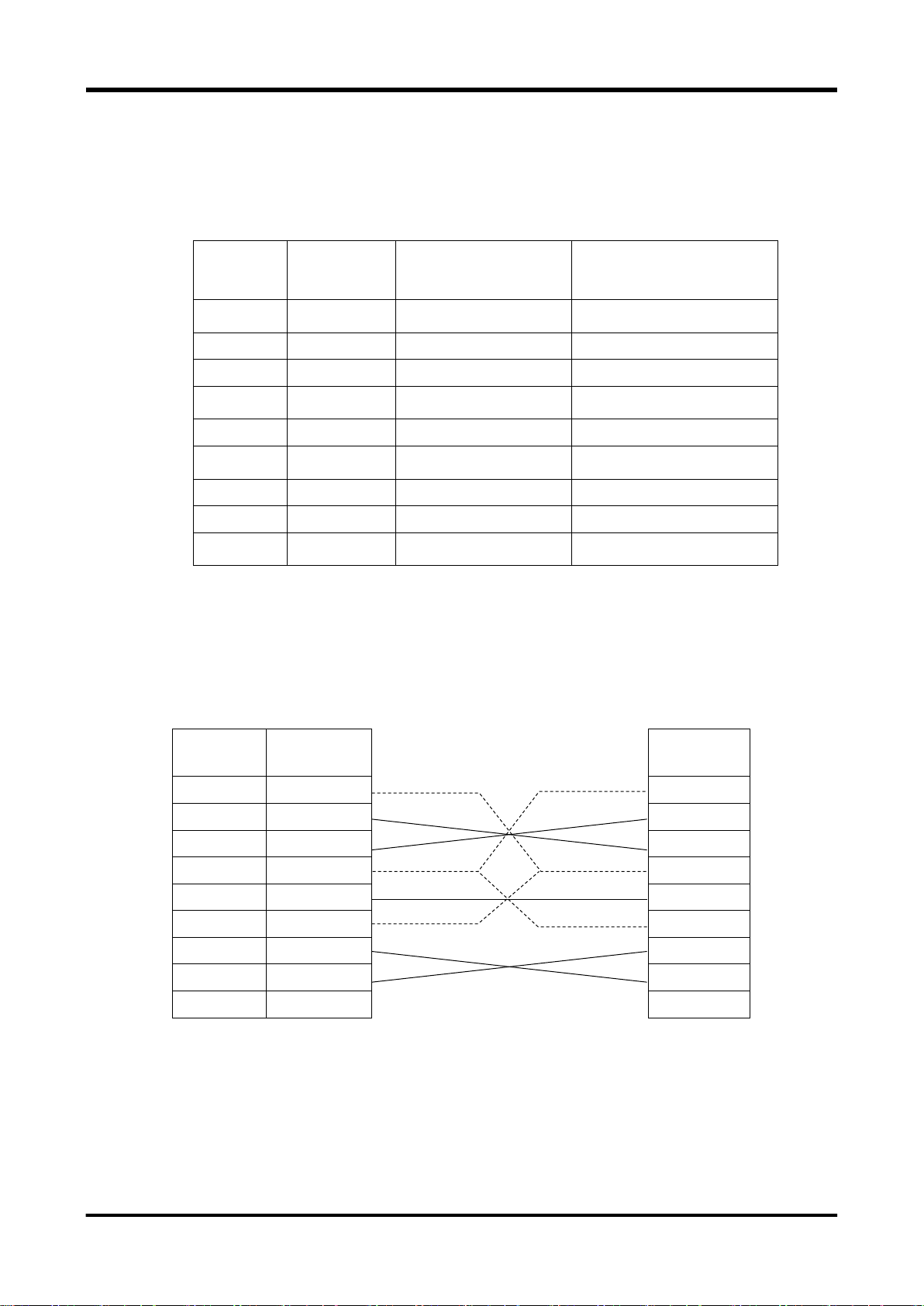
2.5.2 Connection with external instruments
The RS-232 port of this instrument uses a 9-pin D-SUB connector and inch screws (4-40 UNC).
The following Table shows the signal lines and functions of the RS-232 interface.
When connecting the instrument to a personal computer, use of cable generally called “cross cable”
makes it possible to perform the remote control. However, to ensure safe operation, check the
connector shape and pin assignments of both the instrument and computer before connecting to the
personal computer, and then prepare a proper cable.
This instrument External instrument
10

2.5.3 Communication mode
This instrument uses the full-duplex communication method. Therefore, the instrument may start
sending the response message even while it is receiving the message. Normally, this is not a problem
since the data receive buffer is provided. However, if any problem is foreseen, the flow control must
be taken into consideration.
This instrument performs the hardware flow control. The instrument does not have other flow controls
and the hardware flow control cannot be made invalid.
With this instrument, when internal processing lacks the space to obtain input data, the RTS signal is
set to low level. When there is room for this processing, the RTS signal is set to high level.
This instrument is unable to transmit data when the CTS signal is at low level.
2.5.4 Synchronization
This instrument can use only hardware flow control for the synchronization in the serial
communication with the external instrument.
To perform the synchronization with the software, it is recommended to create a remote program that
the last message unit of the message to be sent to this instrument is used as a query (command that
requests the response message from this instrument) and the next message is sent after the
response has been received from this instrument. OPC? query (see section 3.4.5), etc. can be used.
2.5.5 Remote/local control
a. Local mode
In the local mode, operation of the instrument is controlled through panel key operation.
The REMOTE LED is off.
This instrument enters the local mode when the power is turned on.
The following two kinds of methods are provided to return the mode from the remote mode to the local
mode.
Turn off the power, and turn it on again.
Press the LOCAL ([RES]) key.
b. Remote mode
In the remote mode, operation of the instrument is controlled by messages sent through the interface.
All panel key entries except for the LOCAL ([SHIFT]) key become invalid.
The REMOTE icon is lit during remote control.
If the instrument receives the message from the external instrument, it then enters the remote mode.
At this time, as soon as the instrument receives the start byte of the message correctly, it then enters
the remote mode.
c. Local lock out mode
This instrument does not support local lock out mode other than for the GPIB interface. When a lock
out operation is necessary, use the GPIB interface.
11

Setting
Function
Address
Sets instrument address (listener address, talker address).
Values from 0 to 30 can be set.
DELIM
Set delimiter. (For transmission)
Select one of the following: CRLF, LF.
EOI is sent regardless of the setting.
2.6 Remote control through GPIB interface
Remote control of this instrument via a GPIB interface is enabled by connecting the GPIB port on the
rear panel to a computer.
The electrical, mechanical, and functional specifications conform to the IEEE Std.488.1-1987 and JIS
C 1901-1987.
Specifications related to commands, formats, protocols, etc., conform to IEEE Std. 488.2-1987.
The GPIB interface is a factory option (GPIB interface: SC-363).
2.6.1 Settings for this instrument
Set “GPIB” for REMOTE under the SYSTEM menu.
The following types of settings can be entered as GPIB settings (these settings cannot be changed
via remote control).
Table 2-4. Communication Settings when GPIB Is Selected for REMOTE
When this instrument receives a message, it is recognized as a delimiter, regardless of whether the
message is LF, CRLF, or EOI.
12

SH1
Supports all source handshake functions.
AH1
Supports all acceptor handshake functions.
T5
Specifies and cancels the talker by means of basic talker, serial poll, and MLA.
TE0
Does not support the extended talker function.
L4
Specifies and cancels the listener by means of basic listener and MTA.
LE0
Does not support the extended listener function.
SR1
Supports all the service request functions.
RL1
Supports all the remote local functions.
PP0
Does not support the parallel poll function.
DC1
Supports all instrument clear functions.
DT1
Supports all instrument trigger functions.
C0
Does not support the controller function.
E2
Uses the 3-state driver.
2.6.2 Interface functions
This instrument has the IEEE488.1 subsets about GPIB as shown in Table 2-5.
Table 2-5. GPIB interface functions
2.6.3 Connections
CAUTION
Before connecting or disconnecting the cables, always turn off the power to all the instruments
connected to the GPIB cable.
To operate the GPIB system, turn on all the instruments connected to the system bus.
a. Up to 15 GPIB instruments can be connected to one system.
b. The total length of the cables used to connect instruments in the system is 20m or less and 2m
(the number of instruments making up the system) or less.
c. The length of each cable used in the system is freely decided by the person in charge of
system configuration.
However, if the length of the cable connecting two instruments is 4m or more, noise margin
shall be taken into consideration.
d. A desired cable connection method (star or daisy chain, etc.) can be selected by the user.
However, use of the connection that creates the ground loop is not allowed.
e. The number of cable stacks on the connector located on the rear panel of the instrument shall
be 3 or less due to mechanical strength.
f. The connection cable applicable to the IEEE 488.1 or JIS C 1901 standard shall be used.
To improve the reliability of the system, it is recommended to use the cable, on which the EMS
measures are taken (connector with metallic housing).
g. The GPIB system needs to be operated in an electrically and mechanically good environment.
Before configuring the system, see clause 6 and appendix J of JIS C 1901-1987.
13

2.6.4 Remote/local control
This instrument has all the remote and local functions defined in the IEEE Std. 488.1-1987 and JIS C
1901-1987. For details about transition of the remote and local modes, see the section, RL function, in
the specification.
a. Local mode
In the local mode, operation of the instrument is controlled through panel key operation.
The REMOTE LED is off.
This instrument enters the local mode when the power is turned on.
The following four kinds of methods are provided to return the mode from the remote mode to the
local mode (if the GP-IB interface is used).
Turn off the power, and turn it on again.
Set the REN line to “false” (electrically high level).
Press the LOCAL ([SHIFT]) key.
Set this instrument to listener and send the address command GTL.
b. Remote mode
In the remote mode, operation of the instrument is controlled by messages sent through the
interface. All panel key entries except for the LOCAL ([SHIFT]) key become invalid.
The REMOTE icon is lit during remote control.
To change the operation mode of the instrument from the local mode to the remote mode, it is
necessary to set this instrument to listener (MLA is received) with the REN line set at “true”
(electrically low level).
c. Local lock out mode
This instrument enters the local lock out mode in any of the following cases.
The universal command LLO is received in the remote mode.
The instrument enters the remote mode after the universal command LLO has been received.
In the local lock out mode, it is prevented that the mode is returned to the local mode even though
the operator presses the LOCAL ([SHIFT]) key.
The operation and response except for that the LOCAL ([SHIFT]) key input is ignored are the
same as those in the remote mode.
To return the instrument from the local lock out mode to the local mode, set the instrument to
listener and send the GTL message. However, when the mode is changed to the remote mode
again, the instrument enters the local lock out mode even though the LLO command is not
received newly.
To cancel the local lock out mode completely (to return to the remote mode), it is necessary to
temporarily change the mode to the local mode in any of the following manner.
Turn off the power, and turn it on again.
Set the REN line to “false” (electrically high level).
14

2.6.5 GET (Group Execute Trigger)
This instrument starts measurement when the address command GET was received in which
measuring status is trigger wait status and the trigger source is BUS.
When the instrument receives the GET command, the NDAC signal is held to hold the handshake off
until the internal process (starting of measurement) is completed.
2.6.6 DCL・SDC
Upon receiving the universal command DCL (Instrument Clear), this instrument initializes the
instrument function. The same initialization occurs when this instrument is being set to “listener” and
receives the address command SDC (Selected Instrument Clear).
The DCL or SDC message shows that the following initialization is being executed.
Data input/output is terminated, and the input buffers and the output queue are cleared. The
MAV bit of status byte register is also cleared. (As a result, the MSS bit may be affected by
these operations.) See section “3.3 Status report structure.”
If the instrument is performing the measurement, the measurement is stopped and the
instrument is put in the HOLD mode.
When this instrument receives the DCL or SDC interface message, the NDAC signal is held to hold
the handshake off until the internal microprocessor recognizes the signal receive.
2.6.7 Handshake
If the delimiter or EOI reception detects the end of the message, interpretation of the command in the
buffer starts. During command interpretation or execution, the next message is not received. At the
beginning byte of the next message, handshake is held off. If command interpretation or execution
ends, handshake restarts.
15

<PROGRAM MESSAGE>
→<PROGRAM MESSAGE>
<CHARACTER PROGRAM DATA>
→<CHARACTER PROGRAM DATA>
<DECIMAL NUMERIC PROGRAM DATA>
→<NUMERIC PROGRAM DATA>
<SUFFIX PROGRAM DATA>
→<SUFFIX PROGRAM DATA>
<STRING PROGRAM DATA>
→<STRING PROGRAM DATA>
<RESPONSE MESSAGE>
→<RESPONSE MESSAGE>
<CHARACTER RESPONSE DATA>
→<CHARACTER RESPONSE DATA>
<NR1 NUMERIC RESPONSE DATA>
→<NR1 NUMERIC RESPONSE DATA>
<NR2 NUMERIC RESPONSE DATA>
→<NR2 NUMERIC RESPONSE DATA>
<NR3 NUMERIC RESPONSE DATA>
→<NR3 NUMERIC RESPONSE DATA>
<STRING RESPONSE DATA>
→<STRING RESPONSE DATA>
<ARBITRARY ASCII RESPONSE DATA>
→<ARBITRARY ASCII RESPONSE DATA>
3. Remote Control Commands
3.1 Command system
This instrument supports two command systems below. Before using this instrument, use COMMAND
of SYSTEM-REMOTE menu to select which command system is used.
- SCPI compliance (default)
It is the command system in accordance with SCPI which is widely used for instrument
control. It allows all functions of this instrument to be used.
- VOAC752 x series compliance
This command system is compatible with VOAC752x series; i.e. Iwatsu existing product. It
cannot use all functions of this instrument. Use it to divert the existing control program.
3.2 Message rules
For remote control of this instrument, the controller (computer) sends program messages according
to the format structure.
The remote commands used by this instrument conform to general-purpose interface bus (GPIB)
IEEE Std. 488.2. With regard to USB, LAN, and RS-232 interfaces as well, all applicable parts are
similar to the GPIB interface.
Remarks:
The elements defined in IEEE 488.2 are given as follows.
In this instruction manual, Command syntax/Query syntax are to write as following rules:
Parameter choices are to enclose by brace “{}” and each choice is to punctuate by vertical bar
“|.” Only one choice can be used from the choices. Both brace/vertical bar do not send as program
message.
16
 Loading...