

Iwatsu SS-7804, SS-7805, SS-7810 Service Manual

Service Manual
Oscilloscope
SS-7810/05/04
Introduction
◇ Thank you very much for your purchase of Iwatsu electronic measuring instruments.
◇ Please adjust or calibrate your instrument after throughly reading this service manual
and understanding its contents. After reading this manual, please keep it for future
reference.
Cautions for safe use
Matters that must be observed for operation of this instrument and for prevention of injury to
humans and damage to property are described as “ warnings” and “ cautions” in this
service manual.
Explanation of “ Warnings” and “ Cautions” coulmns in this manual
Warning
Incorrect operation or failure to need warnings may result in death
or serious injury.
Incorrect operation or failure to need cautions may result in injury
Caution
or damage to equipment.
Cautions
◇ Parts of the contents of this service manual may be modified without notice to
accommodate improvements in performance and function.
◇ Reproduction of the contents of this service manual without previous consent is
prohibited.
History
◇ Jan. 2004 : Issue of the 1st edition
KML045311 A1-523150(B)
0-1
Warnings
Use care when servicing with power on:
Dangerous voltages exist at several points in this product. To avoid personal injury, do not
touch exposed connections or components while power is on.
Disconnect power before removing protective panels, soldering, or replacing components.
Cautions
●●
● Never place a heavy substance on the power cord:
●●
It will cause an electric shock or fire.
●●
● Prior to connecting or disconnecting the power cord, set the power supply to STBY:
●●
Its negligence will cause an electric shock or trouble.
●●
● Use the specified AC power to operate the instrument:
●●
Use of non-specified power will cause an electric shock, fire, or trouble. The available AC
power supplies are as follows:
・ Supply voltage : 90 to 132V AC/180 to 250V AC
・ Frequency : 48 to 440Hz
・ Power consumption : Max. 110VA
●●
● Use a 3-core power cord suitable to the supply voltage:
●●
Use of other cord will an electric shock or fire.
●●
● When replacing a fuse, be sure to use our specified one (
●●
Use of other fuse will cause a fire or trouble.
●●
● Do not place any substance near the air vent of this instrument or fan:
●●
It will cause a fire or trouble.
●●
● Use the instrument within the specified operating range:
●●
Otherwise, it will cause a trouble. An available temperature range is as follows:
・ Temperature : 0 to 40℃
・ Relative humidity : 90% RH(40℃)
●●
● Do not apply an overvoltage to the input terminal:
●●
It will cause a trouble. A maximum allowable input voltage is as follows:
・ CH1, CH2, CH3 (EXT):
Directly : Max. ±400V
・ When the SS-087R (10:1) or SS-088 (1:1, 10:1) probe is used:
At 10:1 : Max. ±600V
At 1:1 : Max. ±400V
[NOTE] The maximum input voltage decreases depending on frequency and high voltage pulse of the input signal.
φφ
××
φ5
×20mm, 250VA, 2A, slow):
φφ
××
0-2

Table of Contents
Introduction .................................................................................................................................................... 0- 1
Caution for safe use ...................................................................................................................................... 0- 1
Warnings ....................................................................................................................................................... 0- 2
Cautions ........................................................................................................................................................ 0- 2
Section 1 Specifications ................................................................................................................................. 1- 1
Section 2 Check and Adjustment
2.1 Knowledge Required before Beginning Adjustment .............................................................................. 2- 1
2.1.1 Introduction .................................................................................................................................... 2- 1
2.1.2 Check and Adjustment Intervals ..................................................................................................... 2- 1
2.1.3 Menu Screen .................................................................................................................................. 2- 1
① Menu Tree SS-7810/05/04 ........................................................................................................ 2- 2
② Manual Adjustment Menu ..........................................................................................................2- 3
③ Menu Screen (f:MAN-ADJ, AUTO-ADJ, AUTO-CONF) ............................................................. 2- 4
④ Key Function/Movement in Adjustment Menu............................................................................ 2- 5
2.1.4 Check and Adjustment Method....................................................................................................... 2- 6
① Check/Adjustment Procedure Flow Chart SS-78** ....................................................................2- 6
② Automatic Adjustment Items ......................................................................................................2- 7
③ Automatic Comfirmetion Items .................................................................................................. 2-8
④ The Check/Adjustment Items and Sequence With Jig IE-1066 ................................................. 2- 9
⑤ The Check/Adjustment Items and Sequence Without Jig IE-1066 ............................................ 2- 10
2.1.5 Check and Adjustment Affected Item.............................................................................................. 2- 11
2.1.6 Test Equipment Required ............................................................................................................... 2- 12
2.1.7 Preparation for Check and Adjustment ........................................................................................... 2- 14
2.1.8 Connection the Adjustment Jig IE-1066 to the SS-78** .................................................................. 2-15
2.1.9 Check and Adjustment Locations ................................................................................................... 2- 16
① POWER BOARD ....................................................................................................................... 2- 16
② ANA BOARDⅠ......................................................................................................................... 2-17
③ ANA BOARDⅡ......................................................................................................................... 2-18
④ HV BOARD ............................................................................................................................... 2- 19
⑤ V MAIN BOARD Ⅰ(SS-7810) .................................................................................................. 2- 20
2.2 DC Power Supply .................................................................................................................................. 2- 21
2.3 CRT Display .......................................................................................................................................... 2- 22
2.3.1 CRT Cathode Voltage .....................................................................................................................2- 22
2.3.2 CRT Heater Voltage ....................................................................................................................... 2- 22
2.3.3 Focus ............................................................................................................................................. 2- 23
2.3.4 Intensity .......................................................................................................................................... 2- 23
2.3.5 Trace Rotation ................................................................................................................................ 2- 24
2.3.6 Orthogonality ..................................................................................................................................2-25
2.4 Check the Key Function in Automatic Confirmation Mode ..................................................................... 2- 26
2.5 Gain (Coarse) ....................................................................................................................................... 2- 27
2.5.1 Vertical Gain ................................................................................................................................... 2- 27
2.5.2 Horizontal Gain ............................................................................................................................... 2- 28
2.5.3 △V Readout Gain .......................................................................................................................... 2- 28
2.5.4 △t Readout Gain ............................................................................................................................ 2- 29
2.6 Crystal Oscillation Frequency ................................................................................................................ 2- 29
2.7 Balance Coarse .................................................................................................................................... 2- 30
2.7.1 Balance Coarse (Automatic Adjustment Menu "D, L") .................................................................... 2- 30
2.7.2 Magnification Gain .......................................................................................................................... 2- 31
0-3

2.8 Vertical Deflection System .................................................................................................................... 2- 32
2.8.1 Flatness CHI/CH2/CH3 (SS-7810) ................................................................................................. 2- 32
2.8.2 Attenuator Compensation CH1/CH2 ............................................................................................... 2- 33
2.8.3 Attenuator Compensation CH3 (SS-7810)......................................................................................2-34
2.8.4 High-frequency Compensation CH1/CH2 .......................................................................................2-34
2.8.5 High-frequency Compensation CH3 (SS-7810) ..............................................................................2-35
2.8.6 Bandwidth ....................................................................................................................................... 2- 36
2.9 Horizontal Deflection System ................................................................................................................ 2- 37
2.9.1 High-speed Sweep Rate ................................................................................................................. 2- 37
2.9.2 Sweep Linearity at High-speed Sweep Rate (SS-7810) .................................................................. 2- 38
2.10 Calibrator Output ................................................................................................................................... 2- 39
2.11 Automatic Adjustment ........................................................................................................................... 2- 40
2.11.1 Automatic Adjustment Item ............................................................................................................. 2- 42
2.11.2 Error Message ................................................................................................................................ 2- 43
2.12 Automatic Confirmation ......................................................................................................................... 2- 50
2.12.1 Automatic Confirmation Items ........................................................................................................ 2- 51
2.13 Manual Adjustment Menu ..................................................................................................................... 2- 52
2.13.1 Manual Adjustment Items ............................................................................................................... 2- 53
2.13.2 Vertical Gain ...................................................................................................................................2-55
2.13.3 Trigger ............................................................................................................................................ 2- 56
2.13.4 X-Y Gain and Position .................................................................................................................... 2- 57
2.13.5 Manual Adjustment Procedure ....................................................................................................... 2- 58
2.14 Adjustment Jig IE-1066 .........................................................................................................................2- 72
2.14.1 Specifications .................................................................................................................................2-72
2.14.2 Preparation.....................................................................................................................................2-72
2.14.3 Adjustment of IE-1066.................................................................................................................... 2- 73
2.14.4 Schematic Diagram ........................................................................................................................ 2- 75
Section 3 Block Diagram
SS-7810 Block Diagram ........................................................................................................................ 3- 1
SS-7805/04 Block Diagram ................................................................................................................... 3- 7
Section 4 Electrical Parts List
SS-7810 Parts List
CH1 ATTENUATOR 1 ........................................................................................................................ 4- 10
CH2 ATTENUATOR 2 ........................................................................................................................ 4- 12
CH3 ATTENUATOR 3 ........................................................................................................................ 4- 14
CH1 1ST PREAMP 4 ......................................................................................................................... 4- 15
CH2 1ST PREAMP 5 ......................................................................................................................... 4- 17
CH1 2ND PREAMP 6 ......................................................................................................................... 4- 18
CH2 2ND PREAMP 7 ......................................................................................................................... 4- 19
CH3 PREAMP 8 ................................................................................................................................. 4- 20
CH SW & DRY LINE DRIV 9.............................................................................................................. 4- 22
V CHARA AMP 10 .............................................................................................................................. 4- 23
V MAIN AMP 11 ................................................................................................................................. 4- 24
V OUTPUT AMP 12 ........................................................................................................................... 4- 25
CH1 TRIG PREAMP 13 ..................................................................................................................... 4- 26
CH2 TRIG PREAMP 14 ..................................................................................................................... 4- 28
CH3 TRIG PREAMP 15 ..................................................................................................................... 4- 29
A/B TRIG SELECT 16 ........................................................................................................................ 4- 30
A TRIG AMP 17 .................................................................................................................................. 4- 31
B TRIG AMP 18 ................................................................................................................................. 4- 32
TV SYNC SEP 19 .............................................................................................................................. 4- 33
0-4

TLC CIRCUIT 20................................................................................................................................ 4- 34
A SAWTOOTH BUFF 21....................................................................................................................4-35
B SAWTOOTH BUFF 22 ................................................................................................................... 4- 36
A TIMING 23 ...................................................................................................................................... 4- 37
B TIMING 24 ...................................................................................................................................... 4- 38
H & Z SW 25 ...................................................................................................................................... 4- 39
H MAIN AMP 26 .................................................................................................................................4-41
H OUTPUT AMP 27 ........................................................................................................................... 4- 42
Z AMP 28 ........................................................................................................................................... 4- 43
PROBE SENCE 29 ............................................................................................................................ 4- 44
ANA BOARD CONTROL 30 ............................................................................................................... 4- 45
ANA BOARD 8 BIT D/A 31 .................................................................................................................4-45
CRT CONT BOARD 32 ...................................................................................................................... 4- 46
H.V. CIRCUIT 33 ................................................................................................................................ 4- 47
CPU BOARD 35 ................................................................................................................................. 4- 49
36 (missing number)
PANEL BOARD 37 ............................................................................................................................. 4- 51
KEY BOARD 38 ................................................................................................................................. 4- 51
POWER 39 ........................................................................................................................................4-52
OVER ALL 40 ..................................................................................................................................... 4- 54
SS-7805/04 Parts List
CH1 ATTENUATOR 1 ........................................................................................................................4-56
CH2 ATTENUATOR 2 ........................................................................................................................4-58
EXT TRIG IN 3 ................................................................................................................................... 4- 60
CH1 1st PREAMP 4 ...........................................................................................................................4-61
CH2 1st PREAMP 5 ...........................................................................................................................4-63
CH1 2nd PREAMP 6 .......................................................................................................................... 4- 65
CH2 2nd PREAMP 7 .......................................................................................................................... 4- 66
CH SW & DRY LINE DRIV 9.............................................................................................................. 4- 67
V CHARA AMP 10 .............................................................................................................................. 4- 68
V MAIN AMP 11 ................................................................................................................................. 4- 69
V OUTPUT AMP 12 ........................................................................................................................... 4- 71
CH1 TRIG PREAMP 13 ..................................................................................................................... 4- 72
CH2 TRIG PREAMP 14 ..................................................................................................................... 4- 73
A TRIG SELECT 16 ........................................................................................................................... 4- 74
A TRIG AMP 17 .................................................................................................................................. 4- 75
TV SYNC SEP 19 .............................................................................................................................. 4- 77
TLC CIRCUIT 20................................................................................................................................ 4- 78
A SAWTOOTH BUFF 21....................................................................................................................4-79
A TIMING 23 ...................................................................................................................................... 4- 80
H & Z SW 25 ...................................................................................................................................... 4- 81
H MAIN AMP 26 .................................................................................................................................4-83
H OUTPUT AMP 27 ........................................................................................................................... 4- 85
Z AMP 28 ........................................................................................................................................... 4- 87
PROBE SENCE 29 ............................................................................................................................ 4- 89
ANA BOARD CONTROL 30 ............................................................................................................... 4- 89
ANA BOARD 8 bit D/A 31 ................................................................................................................... 4- 89
CPU BOARD 35 ................................................................................................................................. 4- 89
PANEL BOARD 37 ............................................................................................................................. 4- 90
V MAIN BOARD .................................................................................................................................... 4- 90
CRT CONT BOARD 32 ...................................................................................................................... 4- 91
H.V. CIRCUIT 33 ................................................................................................................................ 4- 92
CPU BOARD 35 ................................................................................................................................. 4- 94
0-5

KEY BOARD 38 ................................................................................................................................. 4- 96
SS-78LVPS(100M) POWER 39 ......................................................................................................... 4- 97
OVER ALL 40 ..................................................................................................................................... 4-100
Selection 5 Schematic Diagrams
SS-7810
CH1/CH2 ATTENUATOR 1 2 .......................................................................................................... 5- 1
CH3 ATTENUATOR 3 ........................................................................................................................ 5- 2
CH1/CH2 1st PREAMP 4 5 .............................................................................................................5- 3
CH1 2nd PREAMP 6 .......................................................................................................................... 5- 4
CH2 2nd PREAMP 7 .......................................................................................................................... 5- 5
CH3 PREAMP 8 ................................................................................................................................. 5- 6
CH SW & DRY LINE DRIV 9.............................................................................................................. 5- 7
V CHARA AMP 10 .............................................................................................................................. 5- 8
V MAIN AMP 11 ................................................................................................................................. 5- 9
V OUTPUT AMP 12 ........................................................................................................................... 5- 10
CH1 TRIG PREAMP 13 ..................................................................................................................... 5- 11
CH2/3 TRIG PREAMP 14 15 .......................................................................................................... 5- 12
A/B TRIG SELECT 16 ........................................................................................................................ 5- 13
A/B TRIG AMP 17 18 ...................................................................................................................... 5- 14
TV SYNC SEP 19 .............................................................................................................................. 5- 15
TLC CIRCUIT 20................................................................................................................................ 5- 16
A/B SAWTOOTH BUFF 21 22 ........................................................................................................ 5- 17
A/B TIMING 23 24 ........................................................................................................................... 5- 18
H & Z SW 25 ...................................................................................................................................... 5- 19
H MAIN AMP 26 .................................................................................................................................5-20
H OUTPUT AMP 27 ........................................................................................................................... 5- 21
Z AMP 28 ........................................................................................................................................... 5- 22
PROBE SENCE 29 ............................................................................................................................ 5- 23
ANA BOARD CONTROL 30 ............................................................................................................... 5- 24
ANA BOARD 8 BIT D/A 31 .................................................................................................................5-25
CRT CONT BOARD 32 ...................................................................................................................... 5- 26
H.V. CIRCUIT 33 ................................................................................................................................ 5- 27
CPU BOARD 35 ................................................................................................................................. 5- 29
PANEL BOARD 37 ............................................................................................................................. 5- 33
KEY BOARD 38 ................................................................................................................................. 5- 34
POWER 39 ........................................................................................................................................5-35
OVER ALL 40 ..................................................................................................................................... 5- 36
SS-7805/04
CH1/CH2 ATTENUATOR 1 2 .......................................................................................................... 5- 38
EXT TRIG IN 3 ................................................................................................................................... 5- 39
CH1/2 1st PREAMP 4 5 .................................................................................................................. 5- 40
CH1 2nd PREAMP 6 .......................................................................................................................... 5- 41
CH2 2nd PREAMP 7 .......................................................................................................................... 5- 42
CH SW & DRY LINE DRIV 9.............................................................................................................. 5- 43
V CHARA AMP 10 .............................................................................................................................. 5- 44
V MAIN AMP 11 ................................................................................................................................. 5- 45
V OUTPUT AMP 12 ........................................................................................................................... 5- 46
CH1 TRIG PREAMP 13 ..................................................................................................................... 5- 47
CH2 TRIG PREAMP 14 ..................................................................................................................... 5- 48
A TRIG SELECT 16 ........................................................................................................................... 5- 49
A TRIG AMP 17 .................................................................................................................................. 5- 50
TV SYNC SEP 19 .............................................................................................................................. 5- 51
0-6

TLC CIRCUIT 20................................................................................................................................ 5- 52
A SAWTOOTH BUFF 21....................................................................................................................5-53
A TIMING 23 ...................................................................................................................................... 5- 54
H & Z SW 25 ...................................................................................................................................... 5- 55
H MAIN AMP 26 .................................................................................................................................5-56
H OUTPUT AMP 27 ........................................................................................................................... 5- 57
Z AMP 28 ........................................................................................................................................... 5- 58
PROBE SENCE 29 ............................................................................................................................ 5- 59
ANA BOARD CONTROL 30 ............................................................................................................... 5- 60
ANA BOARD 8 BIT D/A 31 .................................................................................................................5-61
CRT CONT BOARD 32 ...................................................................................................................... 5- 62
H.V. CIRCUIT 33 ................................................................................................................................ 5- 63
CPU BOARD 35 ................................................................................................................................. 5- 64
PANEL BOARD 37 ............................................................................................................................. 5- 68
KEY BOARD 38 ................................................................................................................................. 5- 69
POWER BOARD 39 .......................................................................................................................... 5- 70
OVER ALL 40 ..................................................................................................................................... 5- 71
Selection 6 Mechanical Parts Lists and Illstration ..........................................................................................6- 1
0-7


Section 1 Specifications
1
Section 2 Check and Adjustment
Section 3 Block Diagram
Section 4 Electrical Parts List
Section 5 Schematic Diagrams
2
3
4
5
Section 6 Mechanical Parts List
and Illustration
6

Section 1 Specifications
1

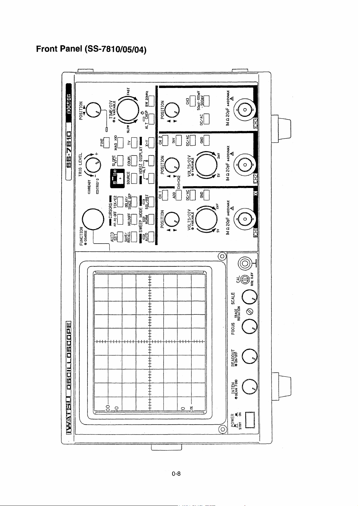
SS-7810
CRT
Type 6 inch, diagonal rectangular flat face, intemal graticule, meshelss
CRT with graticule illumination
Display area 8 div × 10 div (1 div =10 mm)
Accelerating voltage Approx. 16 kV
Vertical defection system (Y axis)
Vertical mode CH1, CH2, CH3, ADD, ALT/CHOP
CH1, CH2 CHOP mode switching rate 555 kHz ± 1 %
Deflection factor
Range 2 mV/div to 5 Vdiv, 1-2-5 sequence, 11 steps
Variable control range 2 mV/div to 12.5 V/div continuously variable
Accuracy ± 2%
Frequency characteristics
Bandwidth
5 mV to 5 V/div DC to 100 MHz −3 dB
2 mV/div DC to 50 MHz −3 dB
Band width limiter DC to approx. 20 MHz
[Note] AC coupled low cutoff frequency (−3 dB) is 4 Hz.
Rise time Approx. 3.5 ns
[Note] Rise time Tr is calculate from:
Tr = [ns]
Step response at 10 mV/div, with 50 Ω termination
Over shoot 3 %
Sag (at 1 KHz) 1 %
Signal delay At least 30 ns of the sweep is displayed before the triggering event.
Input coupling AC, DC, GND
Input RC 1 M Ω±1.5 % // 20pF ± 2pF
Maximum input voltage ± 400 V MAX
Position control range Approx. ±10 div from the center line of the screen
Invert Available on CH2
ADD
Accuracy of sum (at 1 kHz) ± 3%
Frequency characteristics DC to 60 MHz −3 dB
Common-mode rejection ratio at 10 mV/div
1 kHz sin wave 50:1
20 MHz sine wave 15:1
Dynamic range Overranging the screen at 100 MHz in the case of 10 mV/div
Probe sense 10:1, 100:1 detection
350
Bandwidth [MHz]
1-1
CH3
Deflection factor
Range 50 mV/div, 100 mV/div, 500 mV/div
Accuracy ± 2 %
Bandwidth DC to 100 MHz −3 dB
Rise time Approx. 3.5 ns
[Note] Rise time Tr is calculate from:
Tr = [ns]
Step response at 50 mV/div, with 50Ω termination
Over shoot 6 %
Sag (at 1 KHz) 1 % [Note] AC coupled low cutoff frequency (−3 dB) is 10 Hz
Imput coupling AC, DC
Input RC 1 M Ω±1.5 % // 20 pF ±3pF
Maximum input voltage ±400 V MAX
Position control range Approx. ± 10 div from the center line of the screen
Dynamic range Overranging the screen at 100 MHz
Probe sense 10:1, 100:1 detection
Triggering
A triggering
Trigger sensitivity Frequency P.P signal amplitude
DC to 10 MHz 0.4 div
10 MHz to 100 MHz 1.0 div
[Note] TV : The ratio between the composite video signal and
HF-REJ : Attenuates at 10 kHz or more
LF:REJ : Attenuates at 10 kHz or less
Trigger level range ±9.5 div or more (set range: ±10 div)
Signal source CH1, CH2, CH3, LINE, VERT
Coupling AC, DC, HF-REJ, LF-REJ
Slope +, −
B triggering
Trigger sensitivity Frequency P.P signal amplitude
DC to 10 MHz 0.4 div
10 MHz to 100 MHz 1.0 div
[Note] HF-REJ : Attenuates at 10 kHz or more
Trigger level range ± 9.5 div or more (set range: ±10 div)
Signal souroe CH1, CH2, CH3
Coupling AC, DC, HF-REJ, LF-REJ
Slope +, −
TV mode NTSC, PAL, (SECAM)
TV synchronization ODD, EVEN, BOTH TV-H
[Note] ODD/EVN, or BOTH can be seiected
NTSC: 5 H to 2000 H
PAL (SECAM), HDTV: 2 H to 1997 H
350
Bandwidth [MHz]
synchronization signal is 7:3 and synchronization signal
amplitude is 1.5 div or more.
LF-REJ : Attenuates at 10 kHz or less
1-2

AUTO SETUP
Channels Avallable CH1 and CH2
Frequency 50 Hz to 50 MHz
Horizontal deflection system (X axis)
Horizontal display A, ALT, B, X-Y
A sweep
Sweep mode AUTO, NORMAL SINGLE
Sweep rates
Maximum sweep 2 ns/div
Range 20 ns to 500 ms/div 1-2-5 sequence, 23 steps
Variable range 20 ns to 1.5 s/div
Accuracy Ⅰ± 2 % over center 8 div
Accuracy Ⅱ± 5 % over center any 2 div within center 8 div
Hold-off time Countinuously variable
B sweep
Delay Triggered delay or continuous delay (RUNS AFTER)
Sweep rates
Maximum sweep 2 ns/div
Range 20 ns to 5 ms/div 1-2-5 sequence, 17 steps
Accuracy Ⅰ± 2 % over center 8 div
Accuracy Ⅱ± 5 % over center any 2 div within center 8 div
Delay time
Position control range 0.2 to 10.2 div
Accuracy ± [(set value × 0.005)+(sweep rate × 0.1)]−55 ns with in range
of 1 μs/div to 500 ms/div
Delay pick off jitter 1/2000, at 1 ms/div of A sweep:, at 500 ns/div of B sweep
Sweep magnification
Magnifying ratio 10 times
Accuracy Ⅰ over center 8 div
20 ns/div, 50 ns/div ± 5 %
100 ns/div to 500 ms/div ± 3 %
1
*
Accuracy Ⅱ Over any 2 div within center 8 div
20 ns/div, 50 ns/div ± 8 %
100 ns/div to 500 ms/div ± 5 %
*1 30 ns or 1 div at the beginning of sweep and 30 ns at the end of sweep are excluded.
X-Y operation
X axis (CH1)
Deflection factor Same as CH1
Accuracy ± 4 %
Bandwidth DC to 2 MHz, −3 db
Y axis CH1, CH2, CH3, ADD
Phase difference between × axis and Y axis
3' or less (DC to 200 kHz)
CAL (Probe calibration signal)
Waveform Rectangular wave
Fraquency 1 kHz ± 0.1 %
Duty ratio 49 % to 51 %
Output voltage 0.6 V ± 1%
1-3

Measurement with cursors and counter
Measurement with cursors
Type of measurement Time difference ( △ t), Voltage difference ( △ V)
Cursor position control range
X axis ± (5 ± 0.2) div from the center line of the screen
Y axis ± (4 ± 0.2) div from the center line of the screen
Accuracy
Voltage difference ( △ V) ± [(2 % of reading) + (0.3 % of full scale)]
Time difference ( △ t)
MAG OFF ± [(2 % of reading) ± (0.3 % of full scale)]
MAG ON (MAG × 10)
500 ms to 100 ns/div ± [(3 % of reading) + (0.3 % of full scale)]
50 ns, 20 ns/div ± [(5 % of reading) + (0.3 % of full scale)]
Counter
Number of digits displayed 5 digits
Accuracy ± 0.01 %
Frequency measurement range 2 Hz to 100 MHz
Saving data Backup by built-in battery
Type of date to be saved Panel setup conditions immediately before turning power off *
Storing of panel setup conditions *3 (SS-7821/11)
*2 The state where the power cord is disconnected.
*3 The maximum number of date items that can be stored: 32
Data retention time Approx. 30000H (at approx. 25 ℃)
Power source
Voltage range 90 to 132 VAC / 180 to 250 VAC
Frequency range 48 to 440 Hz
Power consumption 110 VA MAX
2
Mass and Dimension
Mass Approx. 7.5 kg (without accessories)
Dimension Approx. 272W × 152 H × 390 L [mm]
[Note] Without accessories, and projections.
Environmental condtions
Specification assurance temperature 10 to 35 ℃
Operating
Temperature 0 to 40 ℃
Humidity 90 % RH or less (at 40 ℃)
Storage
Temperature −20 to 70 ℃
Humidlty 80 % RH or less (at 70 ℃)
Altitude
Operating 5000 m, atmospheric pressure: Approx. 55 kPa
Nunoperating 15000 m, atmospheric pressure: Approx. 12 kPa
Vibration 15 minutes along each of three axes at a total displacement of 0.67
mmp. p with frequency Varied from 10 Hz to 55 Hz in 1 minute sweep.
1-4

Shock Lifting a side to a height of 10 cm and dropping it naturally onto hard
wood: 4 times on each side.
Dropping packaged Dropping an instrument packaged for transportation from a height of
90 cm.
Warm up time The specifications for this instrument are the assured values after
more than 30 min of power on.
1-5

SS-7805/04
CRT
Type 6 inch, diagonal rectangular flat face, internal graticule, meshelss
CRT with graticule illumination
Display area 8 div × 10 div (1 div =10 mm)
Accelerating voltage Approx. 16 kV
Vertical deflection system (Y axis)
Vertical mode CH1, CH2, ADD, ALT/CHOP
CH1, CH2 CHOP mode switching rate 555 kHz ± 1 %
Deflection factor
Range 2 mV/div to 5 V/div, 1-2-5 sequence, 11 steps
Variable control range 2 mV/div to 12.5 V/div continuously variable
Accuracy ± 2%
Frequency characteristics
Bandwidth
5 mV to 5 V/div DC to 40 MHz −3 dB (SS-7804) / DC to 50 MHz −3 dB (SS-7805)
2 mV/div DC to 20 MHz −3 dB (SS-7804) / DC to 20 MHz −3 dB (SS-7805)
Rise time
SS-7804 Approx. 8.75 ns
SS-7805 Approx. 7.0 ns
[Note] Rise time Tr is calculate from:
Tr = [ns]
Step response at 10 mV/div, 50 Ω termination
Over shoot 3 % (SS-7804) / 8 % (SS-7805)
Sag (at 1 kHz) 1 % (SS-7804) / 1 % (SS-7805)
Signal delay At least 30 ns of the sweep is displayed before the triggering event.
Input coupling AC, DC, GND
Input RC 1 M Ω±1.5 % // 25 pF ± 2 pF
Maximum input voltage ± 400 V (DC+ACpeak)
Position control range Approx. ±10 div from the center line of the screen
Invert Available on CH2
ADD
Accuracy of sum (at 1 kHz) ± 3%
Frequency characteristics DC to 20 MHz −3 dB
Common-mode rejection ratio
50:1 1 kHz sine wave
15:1 20 MHz sine wave
Dynamic range Overranging the screen at 40 MHz (SS-7804)
Overranging the screen at 50 MHz (SS-7805)
Probe sense
Attached probe No function.
Optional probe 10:1, 100:1 detection
350
Bandwidth [MHz]
1-6

Triggering
Trigger sensitivity
Frequency CH1, CH2 EXT
DC to 5 MHz 0.4 div 80 mV
5 MHz to 40 MHz (SS-7804)
5 MHz to 50 MHz (SS-7805)
1.0 div 200 mV
[Note] TV : The ratio between the composite video signal and
synchronization signal is 7:3 and synchronization signal
amplitude is 1.5 div or more.
HF-REJ : Attenuates at 10 kHz or more
LF-REJ : Attenuates at 10 kHz or less
Trigger level range ±9.5 div or more (set range: ±10 div)
Signal source CH1, CH2, EXT, LINE, VERT
Coupling AC, DC, HF-REJ, LF-REJ
Slope +, −
TV mode NTSC, PAL (SECAM)
TV synchronization ODD, EVEN, BOTH TV-H
[Note] ODD, EVEN, or BOTH can be selected
NTSC: 5 H to 2000 H
PAL (SECAM): 2 H to 1997 H
EXTTRIG
Input RC 1 MW ±2 % // 25 pF ±3 pF
Input coupling DC
Maximum input voltage ±400 V (DC+ACpeak)
Probe sence 10:1 and 100:1 detection with an optional probe (SS-78R)
Horizontal deflection system (X axis)
Horizontal display A, X-Y
Sweep mode AUTO, NORMAL SINGLE
Sweep rates
Maximum sweep 10 ns/div
Range 100 ns to 500 ms/div
Variable range 100 ns to 1.25 s/div
Accuracy Ⅰ± 2 % over center 8 div
Accuracy Ⅱ± 5 % over center any 2 div within center 8 div
Hold-off time Countinuously variable
Sweep magnification
Magnifying ratio 10 times
Accuracy Ⅰ over center 8 div
100 ns/div to 200 ns/div ± 5 %
500 ns/div to 500 ms/div ± 3 %
1
*
Accuracy Ⅱ Over any 2 div within center 8 div
100 ns/div to 200 ns/div ± 8 %
500 ns/div to 500 ms/div ± 5 %
1-7

X-Y operation
X axis (CH1)
Deflection factor Same as CH1
Accuracy ± 3 %
Bandwidth DC to 2 MHz −3 dB
Y axis CH1, CH2, ADD
Phase difference between × axis and Y axis
3°or less (DC to 50 kHz)
CAL (Probe calibration signal)
Waveform Rectangular wave
Fraquency 1 kHz ± 0.1 %
Duty ratio 49 to 51 %
Output voltage 0.6 V ± 1%
Measurement with cursors and counter
Measurement with cursors
Type of measurement Time difference ( △ t), Voltage difference ( △ V)
Cursor position control range
X axis ± (5 ± 0.2) div from the center line of the screen
Y axis ± (4 ± 0.2) div from the center line of the screen
Accuracy
Voltage difference ( △ V) ± [(2 % of reading) + (0.3 % of full scale)]
Time difference ( △ t)
MAG OFF ± [(2 % of reading) + (0.3 % of full scale)]
MAG ON (MAG × 10)
100 ns, 200 ns/div ± [(5 % of reading) + (0.3 % of full scale)]
500 ns to 500 ms/div ± [(3 % of reading) + (0.3 % of full scale)]
Counter
Number of digits displayed 5 digits
Accuracy ± 0.01 %
Frequency measurement range
SS-7804 2 Hz to 40 MHz
SS-7805 2 Hz to 50 MHz
Saving data Backup by built-in battery
Type of date to be saved Panel setup conditions immediately before turning power off *
*2 The state where the power cord is disconnected.
Data retention time Approx. 30,000H (at approx. 25 ℃)
Power source
Voltage range 90 to 132 VAC / 180 to 250 VAC
Frequency range 48 to 440 Hz
Power consumption 110 VA MAX
Mass and Dimension
Mass Approx. 7.5 kg (without accessories)
Dimension Approx. 272W × 152 H × 390 L [mm]
[Note] Without accessories, and projections.
1-8
2

Environmental conditions
Specification assurance temperature 10 to 35 ℃
Operating
Temperature 0 to 40 ℃
Humidity 90 % RH or less (at 40 ℃)
Storage
Temperature ‑20 to 70 ℃
Humidity 80 % RH or less (at 70 ℃)
Altitude
Operating 5,000 m, atmospheric pressure : Approx. 55 kPa
Nunoperating 15,000 m, atmospheric pressure : Approx. 12 kPa
Vibration 15 minutes along each of three axes at a total displacement of 0.67
mmp. p with frequency Varied from 10 Hz to 55 Hz in 1 minute sweep.
Shock Lifting a side to a height of 10 cm and dropping it naturally onto hard
wood: 4 times on each side.
Dropping packaged Dropping an instrument packaged for transportation from a height of
90 cm.
Warm up time The specifications for this instrument are the assured values after
more than 30 min of power on.
1-9

SS-501 (CH2 OUT, Z AXIS IN)
Factory option for the SS-7800 series.
SS-501 : SS-7804/7805
CH2 OUT connector (rear panel)
Outputs a sample of the signal applied to the CH2 signal input.
Z AXIS IN connector (rear panel)
Input a signal for an intensity modulation on screen.
Specification
CH2 OUT
Deflection factor 45 mV ±20 % per one division screen amplitude (at 50 Ω load)
DC level ±100 mV (at 50 Ωload)
Output coupling DC
Bandwidth 20 MHz –3 dB (at 50 Ω load)
Output resistance 50 Ω±20 %
Z AXIS IN
Input voltage 0.5 Vp-p or more
Polarity Positive going signal decreases intensity and
negative going signal increases intensity
Input frequency DC to 5 MHz
Input resistance 4.5 k Ω±20 %
Maximum input voltage ±50 V (DC+ACpeak)
1-10

Section 2 Check and Adjustment
2

Table of Contents
Section 2 Check and Adjustment
2.1 Knowledge Required before Beginning Adjustment .............................................................................. 2- 1
2.1.1 Introduction .................................................................................................................................... 2- 1
2.1.2 Check and Adjustment Intervals ..................................................................................................... 2- 1
2.1.3 Menu Screen .................................................................................................................................. 2- 1
① Menu Tree SS-7810/05/04 ........................................................................................................ 2- 2
② Manual Adjustment Menu ..........................................................................................................2- 3
③ Menu Screen (f:MAN-ADJ, AUTO-ADJ, AUTO-CONF) ............................................................. 2- 4
④ Key Function/Movement in Adjustment Menu............................................................................ 2- 5
2.1.4 Check and Adjustment Method....................................................................................................... 2- 6
① Check/Adjustment Procedure Flow Chart SS-78** ....................................................................2- 6
② Automatic Adjustment Items ......................................................................................................2- 7
③ Automatic Comfirmetion Items .................................................................................................. 2-8
④ The Check/Adjustment Items and Sequence With Jig IE-1066 ................................................. 2- 9
⑤ The Check/Adjustment Items and Sequence Without Jig IE-1066 ............................................ 2- 10
2.1.5 Check and Adjustment Affected Item.............................................................................................. 2- 11
2.1.6 Test Equipment Required ............................................................................................................... 2- 12
2.1.7 Preparation for Check and Adjustment ........................................................................................... 2- 14
2.1.8 Connection the Adjustment Jig IE-1066 to the SS-78** .................................................................. 2-15
2.1.9 Check and Adjustment Locations ................................................................................................... 2- 16
① POWER BOARD ....................................................................................................................... 2- 16
② ANA BOARDⅠ......................................................................................................................... 2-17
③ ANA BOARDⅡ......................................................................................................................... 2-18
④ HV BOARD ............................................................................................................................... 2- 19
⑤ V MAIN BOARD Ⅰ(SS-7810) .................................................................................................. 2- 20
2.2 DC Power Supply .................................................................................................................................. 2- 21
2.3 CRT Display .......................................................................................................................................... 2- 22
2.3.1 CRT Cathode Voltage .....................................................................................................................2- 22
2.3.2 CRT Heater Voltage ....................................................................................................................... 2- 22
2.3.3 Focus ............................................................................................................................................. 2- 23
2.3.4 Intensity .......................................................................................................................................... 2- 23
2.3.5 Trace Rotation ................................................................................................................................ 2- 24
2.3.6 Orthogonality ..................................................................................................................................2-25
2.4 Check the Key Function in Automatic Confirmation Mode ..................................................................... 2- 26
2.5 Gain (Coarse) ....................................................................................................................................... 2- 27
2.5.1 Vertical Gain ................................................................................................................................... 2- 27
2.5.2 Horizontal Gain ............................................................................................................................... 2- 28
2.5.3 △V Readout Gain .......................................................................................................................... 2- 28
2.5.4 △t Readout Gain ............................................................................................................................ 2- 29

2.6 Crystal Oscillation Frequency ................................................................................................................ 2- 29
2.7 Balance Coarse .................................................................................................................................... 2- 30
2.7.1 Balance Coarse (Automatic Adjustment Menu "D, L") .................................................................... 2- 30
2.7.2 Magnification Gain .......................................................................................................................... 2- 31
2.8 Vertical Deflection System .................................................................................................................... 2- 32
2.8.1 Flatness CHI/CH2/CH3 (SS-7810) ................................................................................................. 2- 32
2.8.2 Attenuator Compensation CH1/CH2 ............................................................................................... 2- 33
2.8.3 Attenuator Compensation CH3 (SS-7810)......................................................................................2-34
2.8.4 High-frequency Compensation CH1/CH2 .......................................................................................2-34
2.8.5 High-frequency Compensation CH3 (SS-7810) ..............................................................................2-35
2.8.6 Bandwidth ....................................................................................................................................... 2- 36
2.9 Horizontal Deflection System ................................................................................................................ 2- 37
2.9.1 High-speed Sweep Rate ................................................................................................................. 2- 37
2.9.2 Sweep Linearity at High-speed Sweep Rate (SS-7810) .................................................................. 2- 38
2.10 Calibrator Output ................................................................................................................................... 2- 39
2.11 Automatic Adjustment ........................................................................................................................... 2- 40
2.11.1 Automatic Adjustment Item ............................................................................................................. 2- 42
2.11.2 Error Message ................................................................................................................................ 2- 43
2.12 Automatic Confirmation ......................................................................................................................... 2- 50
2.12.1 Automatic Confirmation Items ........................................................................................................ 2- 51
2.13 Manual Adjustment Menu ..................................................................................................................... 2- 52
2.13.1 Manual Adjustment Items ............................................................................................................... 2- 53
2.13.2 Vertical Gain ...................................................................................................................................2-55
2.13.3 Trigger ............................................................................................................................................ 2- 56
2.13.4 X-Y Gain and Position .................................................................................................................... 2- 57
2.13.5 Manual Adjustment Procedure ....................................................................................................... 2- 58
2.14 Adjustment Jig IE-1066 .........................................................................................................................2- 72
2.14.1 Specifications .................................................................................................................................2-72
2.14.2 Preparation.....................................................................................................................................2-72
2.14.3 Adjustment of IE-1066.................................................................................................................... 2- 73
2.14.4 Schematic Diagram ........................................................................................................................ 2- 75

2.1 Knowledge Required before Beginning Adjustment
2.1.1 Introduction
Periodic check and adjustment maintains reliable performance of this instrument for a long time.
2.1.2 Check and Adjustment Intervals
To measure signals accurately, it is necessary to periodically check and adjust the measuring instrument.
Recommended check and adjustment intervals for this instrument are approx. 6 months.
2.1.3 Menu Screen
For this instrument, there are three of menu screens for check and adjustment.
◇Adjustment Menu Screen
・Adjust 116 items manually on the adjust menu screen.
For further details, refer to "2.13" Manual Adjustment Items".
◇Automatic Adjustment Menu Screen
・Adjust the instrument automatically with the jig IE-1066.
For futrther details, refer to "2.11 Automatic Adjustment".
◇Automatic Confirmation Menu Screen
・Confirm and check the instrument functions and perfomances automatically with the jig IE-1066.
For furher details, refer to "2.12 Automatic Confirmation".
・For KEY confirmation, refer to "2.4 KEY".
Use IE-1066 when carrying out Automatic Adjustment or/and Automatic Confirmation.
・For connections, refer to "2.18 Connection the Adjustment Jig IE-1066.
・For calibration of IE-1066, refer to "2.14 Adjustment Jig IE 1066".
2-1
①①
①Menu Tree SS-7810/05/04
①①
QUIT
PRESS【FUNCTION】KNOB
SAVE ADJUST VALUE
PRESS【FUNCTION】KNOB
DETERMINE ITEM
PRESS
HOLD OFF
TURN【FUNCTION】KNOB
ADJUST VALUE
TURN【FUNCTION】KNOB
SELECT ADJUST ITEM
NORMAL SCOPE MODE
FUNCTION OFF
READ OUT OFF
PRESS SEVERALTIMES
CH2【VOLT/DIV】
MANUAL ADJUSTMENT
SCREEN
PRESS
NORM
DEPRESS 3 second
【FUNCTION】KNOB
SYSTEM MENU
PRESS AUTO
EXECUTE AUTO BAL CAL
QUIT
QUIT
PRESS
SGL/RST
PRESS TCK/C2
AUTOMATIC ADJUSTMENT
TURN【FUNCTION】KNOB
SELECT ADJUST ITEM
PRESS【FUNCTION】KNOB
DETERMINE ITEM
PRESS A
EXECUTE AUTO ADJ
PRESS
SGL/RST
PRESS △V•△t•OFF
AUTOMATIC CONFIRMATION
TURN【FUNCTION】KNOB
SELECT CONF ITEM
PRESS【FUNCTION】KNOB
DETERMINE ITEM
PRESS NORM EXECUTE
AUTO CONF
QUIT
2-2
②②
②Mannual Adjustment Menu
②②
The following describes how to enter the manual adjustment screen.
Procedure
────
──
Enter to Manual Adjustment Menu Screen
────
①Turn off all the functions to disable【FUNCTION】.*
1
*
Condition that f・XXXX is not being displayed at the upper
right of the screen (the delay time, number of TV lines, etc.)
②Press READOUT to set the charactors to OFF
(non-display).
③Press【VOLTS/DIV】of CH2 several times quickly.
・ Manual adjustment menu is displayed.
・ The function indication turns to f:MAN-ADJ.
・ Select the adjustment item by turrning【FUNCTION】.
The steps below describes an example when INTEN is to be
selected.
────
──
────
1
────
──
Selecting the Adjustment Item
────
────
──
────
④Turn【FUNCTION】to select INTEN.
・ For details of the adjustment menu items, refer to the "2.13.5
Manual Adjustment Procedure".
────
──
Setting the Value
────
────
──
────
⑤Press【FUNCTION】.
・ The adjustment item is determined.
⑥Turn【FUNCTION】to set the VALUE.
────
──
Saving the VALUE
────
────
──
────
⑦Press【FUNCTION】.
・ The set value is saved and "SAVED" appears at the lower
left of the screen.
────
──
Canceling the Adjustment Menu Screen
────
────
──
────
⑧To cancel the adjustment menu screen, press HOLD OFF .
2-3
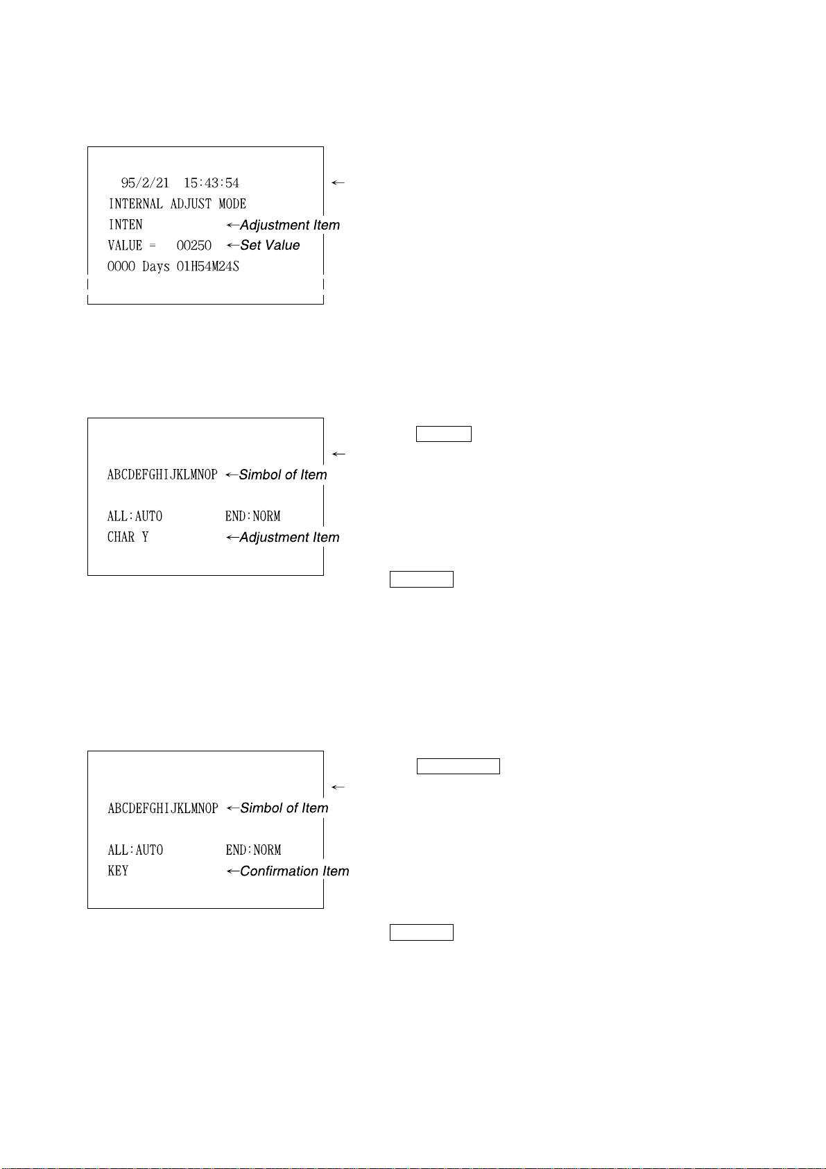
③③
③Menu Screen (f:MAN-ADJ, AUTO-ADJ, AUTO-CONF)
③③
◇Procedure ① to ③, refer to "2.1.3 ② Adjustment Menu".
・ Display the adjustment menu screen.
Automatic Adjustment Menu screen
◇Press TCK/C2 in the manual adjustment screen.
・ Display the automatic adjustment menu screen.
For the automatic adjustment menu, see "2.11 Automatic
Adjustment".
Automatic Confirmation Menu screen
────
──
Return to Manual Adjustment Menu Screen
────
・ To cancel the auto adjustment menu screen, press
SGL/RST .
◇Press △V-△t-OFF in the adjustment menu screen.
・ Display the automatic confirmation menu screen.
・ For the "KEY", see "2.4 KEY on automatic confirmation".
For the items except "KEY", see "2.14 Automatic Confirma-
tion".
────
──
Return to Manual Adjustment Menu Screen
────
・ To cancel the auto confirmation menu screen, press
SGL/RST .
────
──
────
────
──
────
2-4
 Loading...