

Iwatsu DS-8814 Operation Manual

i
Introduction
• Thank you for purchasing this IWATSU’s instrument.
• Please read this manual before using the instrument, then keep the manual handy for
future reference.
• To ensure safe operation of this instrument and to prevent injury to the user or damage
to property, read and carefully observe the warnings and cautions in the following
section.
• This operation manual mainly describes notes on use, operation method through the
panel, examples of use, and performance. For details about remote control through RS232C and GP-IB (special optional cable needs to be used), please refer to the Commands
Manual in the later part of this operation manual.
Note
• Parts of the contents of this manual may be modified without notice for improvements
in performance and functions.
• Reproduction or reprinting of the contents of this manual without prior permission
from IWATSU is prohibited.
• The TFT color LCD contains cold cathode fluorescent lamps. Observe local ordinances
and regulations when disposing of the LCD.
• Windows and MS-DOS are registered trademarks of Microsoft Corporation.
• For questions about this instrument, contact IWATSU TEST INSTRUMENTS
CORPORATION our Homepage listed at the end of this manual or our sales distributor.
Revision History
May 2002 : 1st edition
November 2002 : 2nd edition
KML042321 A201-422500(B)
ii
Safety precautions
To ensure safe operation of this instrument and to prevent injury to the user or damage to
property, read and carefully observe the warnings and cautions in the following section
and associated symbols marked on the panel diagrams.
Definitions of warnings and cautions used in this manual
STAND BY: Standby mode is set when the main power supply of this instrument is
turned OFF.
Explanation of the symbols on the panel
Symbol
Description
Symbols used throughout the manual together with descriptions, to protect
the operator from injury and this instrument from damage.
Indicates that this is a frame or chassis terminal.
Indicates that there is a danger of electric shock
Power ON
Stand by
Incorrect operation or failure to observe the warning may result in death or
serious injury.
Incorrect operation or failure to observe the caution may result in injury or
damage to instrument.
Caution
Warning
iii
Installation
• Do not use in an environment with explosive gases. It may cause an explosion.
• If you notice smoke, foul odor or abnormal noise, immediately stop measuring
to avoid electric shock or fire. Turn off the instrument to be measured and
disconnect the power cable from the power outlet. Please contact our Homepage
listed at the end of this manual or our sales distributor. Do not attempt to repair
the unit yourself.
Power Supply
• Always use this instrument only within the rated operating voltage. If used over
the rated range, electric shock, fire or failure may occur. The range of operating
voltage is stated on the rear panel.
This instrument runs on single-phase, 115 V (90 to 132 V) or 220 V (180 to 250
V), AC power source at 45 to 66 Hz. No voltage selection is required, as the
instrument automatically adapts to the line voltage.
• Use a 3-prong grounded power cord. By connecting the attached 3-prong power
cord to a 3-wire receptacle, the grounding wire of the power cord is connected
to ground. If this is not done, an electric shock or instrument damage could
result. When supplying power from a 2-wire receptacle using a 3-prong/2-prong
conversion adapter, connect the grounding terminal of the 3-prong/2-prong
conversion adapter to ground.
• Use of a 2-prong power cord may result in electric shock.
If the supply voltage is of a 200 V system (200 V to 240 V), use a 200 V system
(rated 250 V) 3-prong power cord.
Read the following safety information.
Warnings
iv
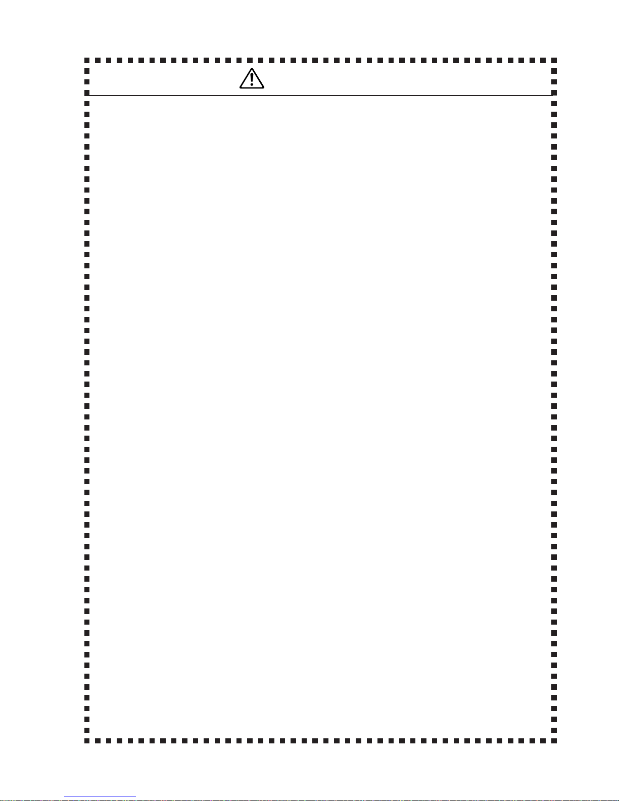
Probe
Probe
Probe
Grounding lead
The chassis is grounded.
Grounding lead
Grounding side
+100 V and the chassis are shorted.
This is dangerous because 100 V is
applied to the chassis.
When measuring
• Connect the probe ground and input connectors to the ground of the device
under test. Refer to “improper ground connections” shown below. Improper
ground connections may cause electric shock or failure of the instrument, the
device under test or other devices connected to the instrument.
[Improper ground connections]
When measuring a floating potential, measurement by the differential method (CH1,
CH2 input) is recommended as shown in the example below.
[Example of recommended measurement]
Read the following safety information.
Warnings
• Power cord
Do not use a damaged power cord or adapter, otherwise fire or electric shock
could result. If the power cord is damaged, please contact our Homepage listed
at the end of this manual or our sales distributor for repair.
• Do not modify the power cord. • Do not pull the power cord.
• Do not forcibly bend the power cord. • Do not heat the power cord.
• Do not twist the power cord. • Do not let the power cord get wet.
• Do not bundle the power cord.
• Do not put heavy objects on the power cord.
v
Operation
• Make sure no water gets on or inside the product
• Do not use the product if wet, otherwise electric shock or fire could result. If
water gets on or inside the unit, turn the power switch to STBY and remove the
power cord. Immediately contact our Homepage listed at the end of this manual
or our sales distributor.
• Do not touch the plug of the power cord with wet hands, otherwise electric
shock could result.
• Operate the instrument on a stable platform. Do not place the instrument on an
unstable support. Dropping the instrument during operation could result in electric
shock, injury, or fire. If the instrument is dropped, turn the power switch to
STBY and remove the power cord. Immediately contact our Homepage listed at
the end of the manual or our sales distributor.
• Do not remove the chassis covers or rear panel. Removing covers exposes lethal
high-voltage circuits within and could result in electric shock.
Please contact our Homepage listed at the end of the manual or our sales
distributor for inspection, calibration, or repair.
• Do not modify this instrument. Modification of this instrument could result in
electric shock, fire, or power failure, and repair of a modified instrument may be
refused.
• Do not operate the instrument in conditions where foreign particles such as metals
or inflammables could pass through the ventilation holes. Operation under these
conditions could result in fire, electric shock, or instrument damage. If any foreign
matter has contaminated the unit, turn the power switch to STBY and remove
the power cord. Immediately contact our Homepage listed at the end of the
manual or our sales distributor.
Warnings
Read the following safety information.
vi
Read the following safety information.
Installation
• Always use this instrument only within the rated operating range. If used over
the rated range, failure may occur.
Use this instrument only indoors.
Operating conditions
Temperature: 0 to +40°C
Humidity: 80% RH or less (non-condensing)
Height: 2,000 meters or less
• Do not block the air ventilation holes or exhaust fan of this instrument. Blocking
the airflow could result in excessive internal heating and fire or electric shock.
• Leave a space behind and to the sides of the instrument.
Be careful to avoid overheating of the instrument when installing the instrument
in a rack mount or on another measurement machine. Failing to observe this
precaution may result in faulty operation or performance.
• Do not place this instrument in a location with excessive moisture or dust,
otherwise fire or electric shock could result.
Power Supply
• Use only the specified fuse (φ5 × 20 mm, 250 V, T3.15 A) when replacing the
fuse. Failure to replace the fuse with the correct rating could result in fire, electric
shock or damage to the unit.
To replace the fuse:
a) Turn the power switch to STBY before disconnecting the power cord.
b) Disconnect the power cord before replacing the fuse.
When measuring
• Do not apply a voltage exceeding the specified value to the input terminals (CH1,
CH2, CH3, CH4). This may cause malfunction. The following is a maximum
voltage that can be input.
Direct
1 MΩ: ±400 V (DC+ACpeak≤5 k Hz)
When SS-0130R (10:1) equivalent probe is used: ±600 V (DC+ACpeak)
[Note]: Maximum voltage that can be input may decrease depending on the
frequency or high voltage pulse of the input signal.
• When a probe or measurement cable is connected, be careful so that you do not
pull the probe or measurement cable causing the instrument to overturn.
Letting the instrument overturn may cause electric shock, injury, fire or
malfunction.
Cautions

vii
Read the following safety information.
Handling
• Set the power switch to STAND BY before connecting or disconnecting the
power cord.
Connecting or disconnecting the power cord while the power is supplied to the
instrument may cause electric shock or malfunction.
• When disconnecting the power cord from the receptacle, remove it by grasping
the plug. Do not pull on the cord itself, as doing so may damage the cord and
could result in fire or electric shock.
• Inspect all cables prior to use. Do not use any damaged cable, otherwise fire or
electric shock could result.
• Do not place any objects on this instrument.
If any objects are placed on this instrument, the cover may be deformed and the
internal circuits shorted, which could result in electrical shock, fire, or damage
to the instrument.
• Be careful not to let the container fall over during set-up and use, otherwise
electric shock, injury, or fire could result.
• Do not use the instrument if broken, otherwise electric shock or fire could result.
Contact our Homepage listed at the end of the manual or our sales distributor for
repair.
• To avoid electric shock or fire, pull out the power supply plug from the outlet for
safety if the instrument will not be used for a long time.
Carrying the instrument
• Dropping the instrument could result in human injury or instrument failure. Be
careful not to drop the instrument and always firmly grasp the middle of the
handle.
(1) Disconnect the cables.
1. Disconnect the power cord and bundle it.
2. Turn counterclockwise and disconnect the connector
of the probe.
(2) Grasp the handle.
1. Raise the handle.
2. Grasp the middle of the handle when carrying
the instrument.
Cautions
+9#657 &+)+6#.15%+..15%12'&5

viii
Read the following safety information.
Cautions before using the floppy disk drive
• Before using the floppy disk drive, make the front panel of the instrument faced
forward. If the instrument is operated with its front panel made faced upward,
write or read error may occur.
Cautions
Good Bad
ix
Check the items included in the package.
When you receive the product, please check the items included. If any item is missing or
damaged , immediately contact our Homepage listed at the end of the manual or our sales
distributor.
Components
• Main unit ............................................................................ 1
• Accessories
10:1 10M Ω SS-0130R Passive Probe ............................. 4
(Accessories Includecl)
Fuse (250 V T3.15 A) ........................................................ 2
Operation・Commands Manual ......................................... 1
Thermal printer paper ......................................................... 1 pcs*
Power cord (3-prong type) ................................................. 1
* Option
Thermal printer paper 10 pcs
Type : TP80-1 Code : 21392-55-00
Adjusting screw-driver
Earth lead
Head
Arrow tip
IC test tip
Earth attachment
Accessories
㨯 Color ring
㨯 Adjusting screw-drive
r
㨯 IC test chip*
㨯 Earth attachment*
Color ring
x
Packing Diagram
Polyethylene bag
Bottom pad
Corner pats
Bottom packing
Figure 1 Main Unit Packing Diagram
Accessory
box
Figure 2 Packing
Main unit
Top packing

xi
Contents
Introduction ...................................................................................................... i
Safety precautions .......................................................................................... ii
Warnings ....................................................................................................... iii
Cautions ........................................................................................................ vi
Check the items included in the package ...................................................... ix
Components .................................................................................................. ix
Menu hierarchy and table of contents .......................................................... xiv
Section 1 Basic Operation ...................................................................................... 1
Appearance .................................................................................................... 2
Rear/Upper view ............................................................................................. 3
Operating buttons and knobs .......................................................................... 4
Menu (FUNCTION) operation ......................................................................... 5
Description of operation section ..................................................................... 6
How to read screen ........................................................................................ 8
Before starting the measurement ............................................................ 10-11
Contrast setting, Selection of language, HELP function, Setting of date ............. 10
Display date on the screen, Reverse display function (LCD),
How to restore the setting at time of purchase ................................................ 11
Displaying CAL waveform by AUTOSET ................................................. 12-13
Probe connection ................................................................................................. 12
Calibrating the probe ............................................................................................ 13
Operating vertical axis .............................................................................14-15
OFFSET, VOLTS/DIV, Zoom ................................................................................ 14
COUPLING, BW, How to use volts ...................................................................... 15
Operating the horizontal axis ................................................................... 16-17
TIME/DIV, DELAY, ZERO DELAY ......................................................................... 16
Sampling rate, Memory length, PERSISTENCE .................................................. 17
Trigger ..................................................................................................... 18-19
Trigger signal, Level ............................................................................................. 18
Trig Type, Slope, Source, Coupling, Hold off ....................................................... 19
Sweep mode ........................................................................................... 20-21

xii
AUTO/NORM/SGL, Sweep mode in roll function ................................................. 20
RUN/STOP ........................................................................................................... 21
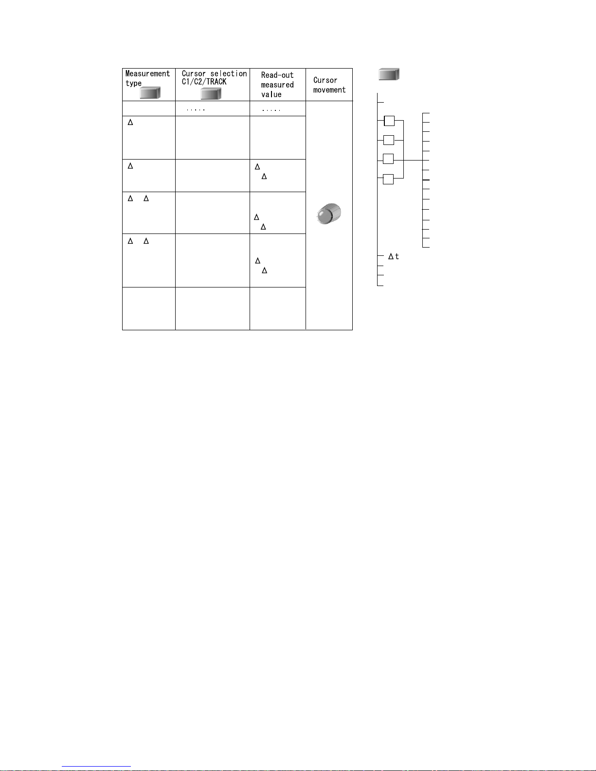
Cursor measurement ............................................................................... 22-23
∆V/∆t/∆V & ∆t/∆V at t/OFF, FUNCTION, C1/C2/TCK ........................................... 22
Type of cursor measurement ............................................................................... 23
Copy function...........................................................................................24-25
Making a hard copy .............................................................................................. 24
Loading printer roll paper ..................................................................................... 25
SAVE/UNDO of SETUP ................................................................................ 26
SETUP SAVE, SETUP UNDO .............................................................................. 26
SAVE/CLEAR button of REF ........................................................................ 27
REF SAVE, REF CLEAR, Display, Recall, Setup ................................................ 27
Acquisition menu ..................................................................................... 28-29
ACQUISITION mode/EQU Sample/Roll/Persist/Length setting ........................... 28
Acquisition mode vs. Sweep range ...................................................................... 29
DISPLAY menu ........................................................................................ 30-31
Contrast/Join/Display TYPE setting ..................................................................... 30
Scale/Math/M Source/Status setting .................................................................... 31
MEASURE (auto measurement) menu .................................................... 32-33
MEASURE, Setting measurement items .............................................................. 32
Measurement item, Auto-measurement parameter ............................................. 33
SAVE/RECALL menu ................................................................................... 36
SAVE/RECALL /Device/Type/Style/Function setting............................................ 36
Saving panel settings to floppy disk ..............................................................37
Recalling panel settings from floppy ............................................................. 37
Saving waveform to floppy disk .................................................................... 38
Recalling waveform data from floppy disk .................................................... 38
Save/Recall menu (continuation) .................................................................. 39
Format setting, Auto save, Default, Delete .......................................................... 39
UTILITIES menu ........................................................................................... 40
Copy/Interface menu setting ................................................................................ 40
Comment/Date/Config menu, Self cal/Auto cal/Update setting ........................... 41
Section 2 Explanation of Functions..................................................................... 43
Waveform display ......................................................................................... 44
Vertical axis .................................................................................................. 45

xiii
Horizontal axis .............................................................................................. 45
Triggering ..................................................................................................... 46
TV trigger...................................................................................................... 48
ACQUISITION .............................................................................................. 50
Peak detection (Peak Det) ................................................................................... 50
Average (Average) ............................................................................................... 51
Equivalent sampling (EQU SMPL) ....................................................................... 52
Roll (ROLL) .......................................................................................................... 53
Sweep mode in Roll operation ............................................................................. 54
Persistence (PERSISTENCE) .............................................................................. 55
Memory length (Length) ....................................................................................... 55
Interleave ...................................................................................................... 56
XY display ..................................................................................................... 57
Calculated waveform .................................................................................... 58
Automatic measurement (MEASURE) .......................................................... 60
Save/recall/delete ......................................................................................... 70
UTILITIES/Copy ........................................................................................... 73
Appendices
Appendix 1:
Sampling Period and On-Screen Data Count for Short Memory ................... 75
Appendix 2:
Sampling Rate and Display Memory Length for Long Memory ...................... 77
Appendix 3: AUTOSET measuring conditions ..................................................... 79
Appendix 4: <Panel setting> to be saved ............................................................ 80
Section 3 Daily Care .............................................................................................. 81
Maintenance method ............................................................................................ 82
Diagnostic guideline ............................................................................................. 84
Section 4 Specifications ....................................................................................... 87
Section 5 FFT Computation.................................................................................F-1
Index..................................................................................................................Index-1
xiv
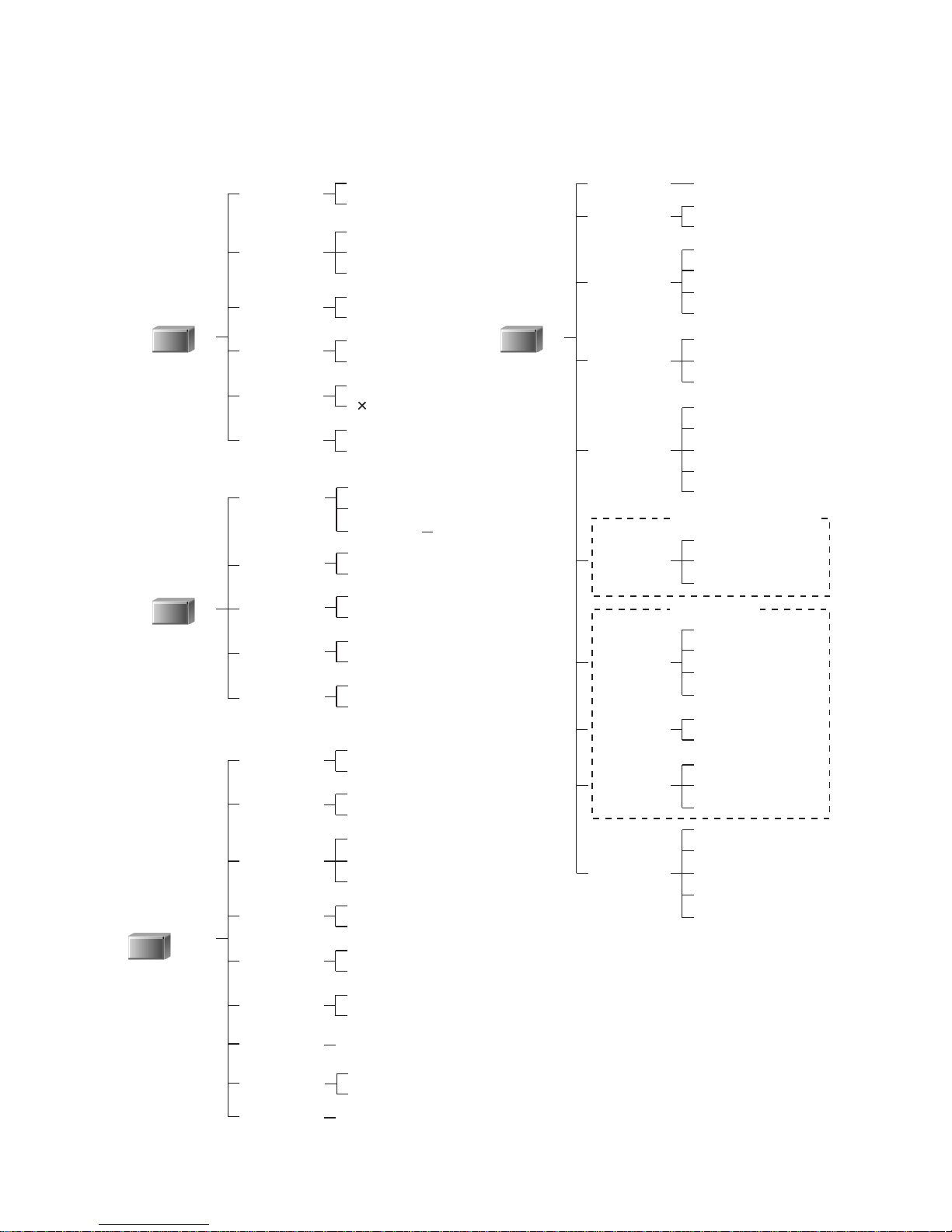
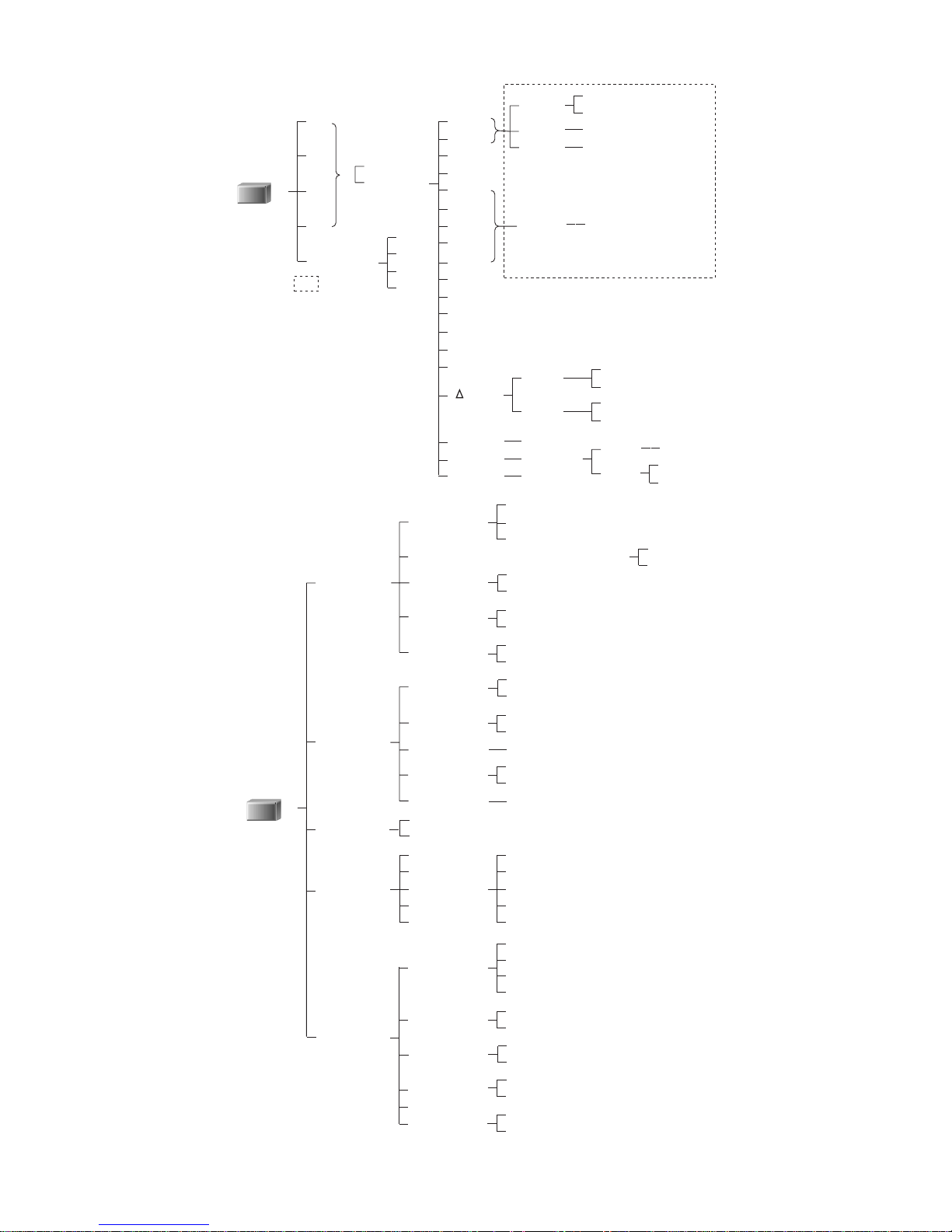
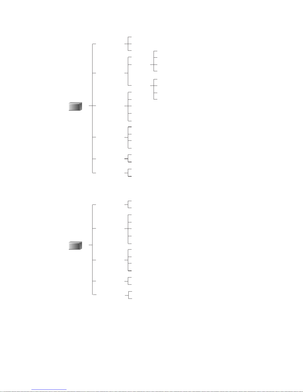
Menu hierarchy and table of contents
The numbers in parentheses indicate reference pages.
On
Off
AC
DC
GND
Auto
1:1 to 1000:1
On
Off
Off
1.01 to 2.50
Division
Volts
Trace
Coupling
Probe
BW
Zoom
Offset
CH1/CH2/
CH3/CH4
Norm Smpl
Peak Det(50)
Average
On
Off
On
Off
On
Off
Short
Long
Mode
Equ Smpl
Roll
Persist
Length
0 to 100%(10)
On
Off
YT
XY1&2
XY3&4
XY1&2/3&4
Grid
Axis
Frame
Off
Add
Sub
Mult
FFT
CH1&CH2
CH3&CH4
CH1&2/CH3&4
CH1
CH2
CH3
CH4
1024
4096
Hanning
Flat Top
Rect
Off
Counter
Date
Measure
Comment
Contrast
Join
Type
Scale
Math
M Source
F Source
F Points
F Window
Status
DISPLAY
ACQUISITION
Floppy
ATA Card
Setup
Waveform
Save
Recall
Delete
Floppy 1 to 200
ATA Card 1 to 9999
Floppy
ATA Card
On
Off
Device
Type
Function
File No
Format
Auto Save
SAVE/RECALL
Count
2 to 256(51)
Style
Step
Binary
ASCII
1, 2, 4, 8, 16, 32, 64, 128
Default
Setup
(12,14,15)
(30,31,44)
(58)
(52)
(53)
(17,55)
(55)
(28,29)
(34 to 39,63,64)
(11)
Math: Add/Sub/Mult
Math: FFT
xv
Tr
Tf
Vrms
Vmean
freq
Period
+PW
-PW
Duty
+Peak
-Peak
P-P
To p
Base
T-B
t
Skew12
Skew34
Skew13
A
B
C
D
Parameter
MEASURE
A
B
C
D
Off
CH1/CH2
/CH3/CH4
100%
Upper
Lower
Top-Base
P-P
11 to 90%
10 to 89%
10 to 90%
Rise
Fall
Set the parameter values
enclosed with dotted line.
Level
Edge
Level
10 to 90%
(32,33,58 to 62)
Edge
Level
Edge
Level
From
To
CH1/CH2
CH3/CH4
CH1/CH3
Copy
Interface
Comment
Date
Config.
UTILITIES
Device
Type, Function (Floppy, ATA Card only)
File No
Auto Copy
Source
Interface
Delimiter
Baud Rate
Data
Address
End
Cancel
Date
Month
Year
Hour
Minutes
Language
(10)
LCD
(11)
Self Cal
Auto Cal
System
Update
Printer
Floppy
ATA card
Floppy 1 to 200
ATA Card 1 to 9999
On
Off
Screen
Panel
RS232C
GP-IB
LF
CR/LF
RS232C only (2400 to 115.2k)
7bits
8bits
GP-IB only (0 to 30)
01 to 31
01 to 12
1999 to 2098
00 to 23
00 to 59
English
Japanese
Simplified Chinese
Traditional Chinese
Normal
Reverse
Cancel
OK
On
Off
Cancel
OK
(40,41)
(24,25,64,65)
(Commands)
(10)
TIFF
BMP
(RS232C only)
xvi
Auto
Normal
Single
Edge
Event
TV
CH1
CH2
CH3
CH4
Line
AC
DC
HF-R
LF-R
Pos
Neg
Off
200ns to 2s
Sweep
Trig Type
Source
Coupling
Slope
Hold off*
TRIGGER
(In any mode
other than
roll mode)
Count
Burst
Extra
Missing
Both
Odd
Even
TV-H
Endless
Trigger’d
CH1
CH2
CH3
CH4
Line
AC
DC
HF-R
LF-R
Pos
Neg
Off
200ns to 2s
Sweep
Source
Coupling
Slope
TRIGGER
(In roll mode)
* "Hold off" exclusively for when Edge of Trig Type is selected
Hold off*
* "Hold off" exclusively for when Edge of Trig Type is selected
(19,20,46)
(53,54)
(20,21)
(20)
xvii
Off
V
t
V/ t12
V/ t34
V at t
V-CI
V-C2
V-TRACK
CH1
CH2
CH3
CH4
H-CI
H-C2
H-TRACK
V-CI
V-C2
V-TRACK
H-CI
H-C2
H-TRACK
t
1/
t
CH1
CH2
t
1/
t
CH3
CH4
t
1/
t
t
CH1
CH2
CH3
CH4
H-C1
FUNCTION
V-CI
V-C2
V-TRACK
H-CI
H-C2
H-TRACK
CURSORS
Tr
Tf
Vrms
Vmean
freq
Period
+PW
-PW
Duty
+Peak
-Peak
P-P
To p
Base
T-B
Off
1
2
3
4
Skew12
Skew34
Skew13
MEASURE

xviii
Memo

Operation Manual

1
Section 1 Basic Operation
This section describes the basic operation including start-up.
See Section 2, “Explanation of Functions” for details.
2
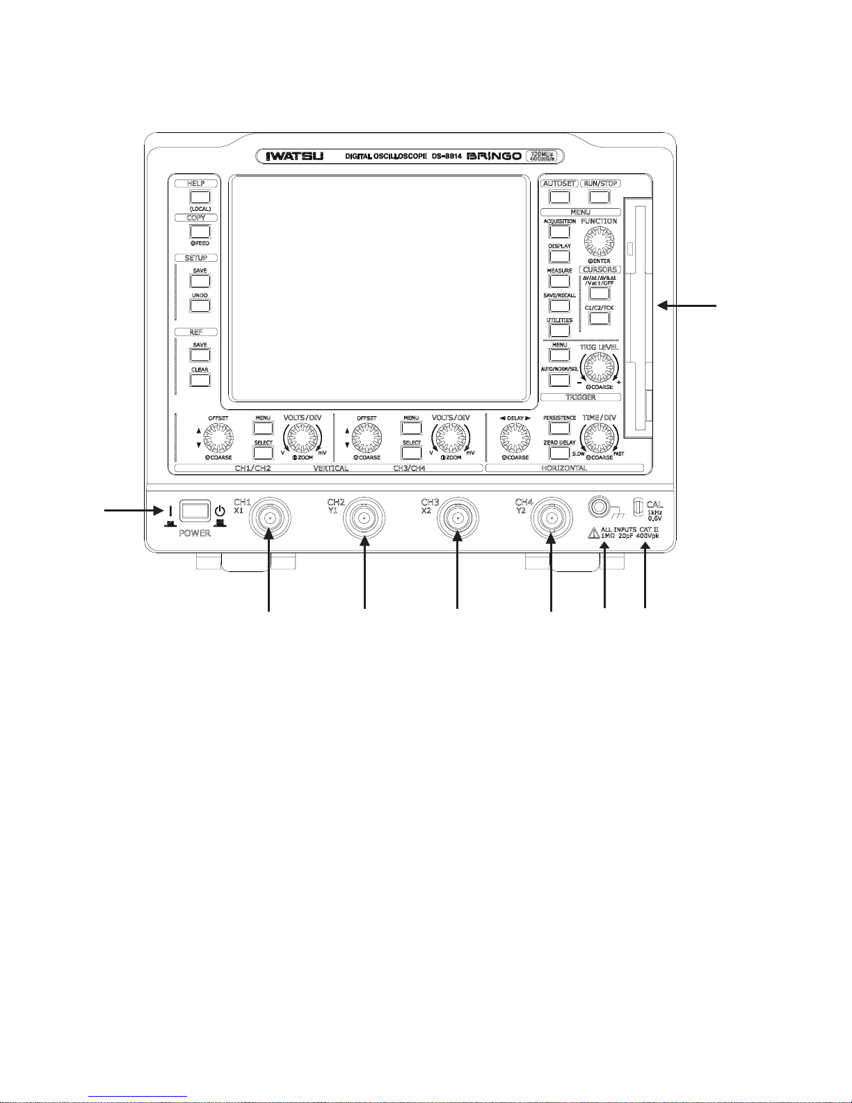
Appearance
Front View
① Power switch
② Input terminal
③ CAL terminal/calibration signal output terminal
④ Ground terminal
⑤ Floppy disk drive
①
②
②③
④
⑤
②
②
3
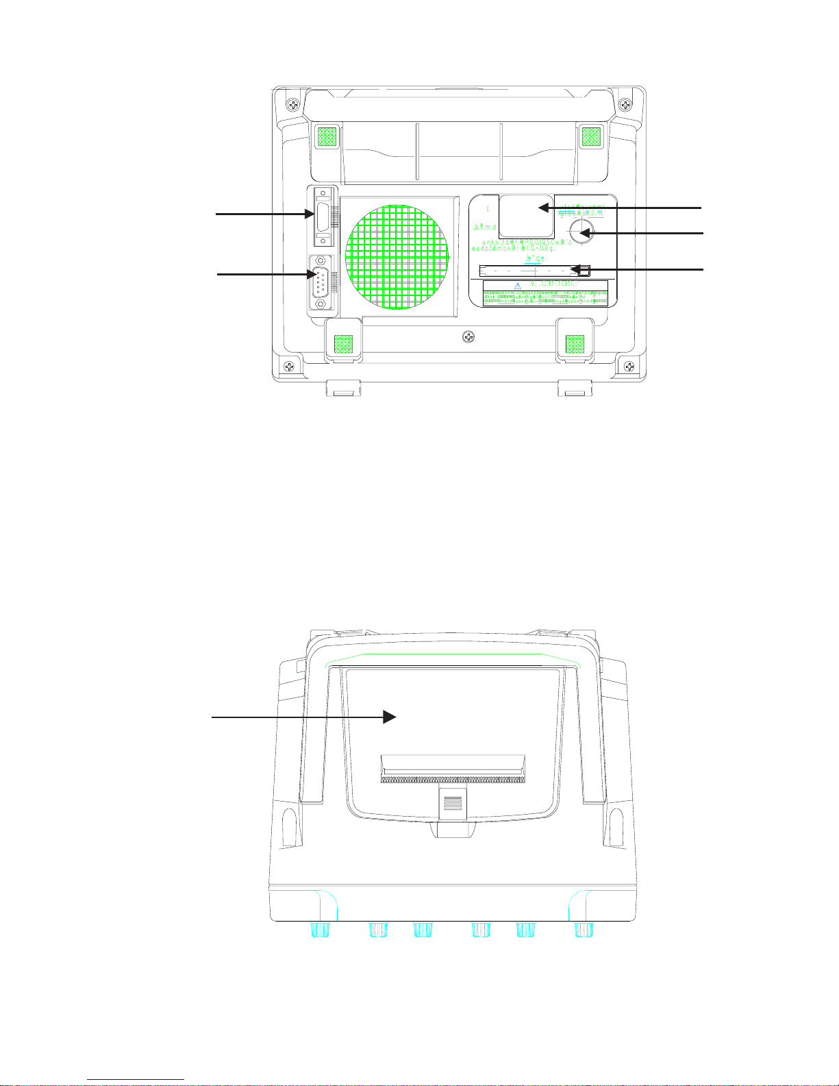
Rear View
① GP-IB port
② RS-232C port
③ AC power inlet
④ Fuse holder
⑤ PCMCIA Type II slot
Upper View
① Built-in printer
①
①
②
⑤
④
③

4
Operating buttons and knobs
Buttons
Single function button: Pressing the button with relevant name executes the associated
function.
AUTOSET, RUN/STOP, HELP, COPY, SETUP SAVE, SETUP UNDO, REF SAVE,
REF CLEAR, ZERO DELAY
Channel change button: Every time the SELECT button is pressed, the channel to be
operated with CH1 and CH2 or CH3 and CH4 is changed. The functions to be changed
are MENU, OFFSET, and VOLTS/DIV.
Function selection button: Pressing the button changes the function.
Cursor: ∆V/∆t/∆V&∆t/V at t/OFF, C1/C2/TCK
Sweep mode: AUTO/NORM/SGL
PERSISTENCE
Menu display button: Pressing the MENU button displays the menu screen. (For the
menu hierarchy, see 0-14 to 19.) The color of the button is gray.
ACQUISITION, DISPLAY, MEASURE, SAVE/RECALL, UTILITIES, CH1/CH2,CH3/
CH4, MENU
Knobs
Single function knob: Turning or pressing the knob sets a range or level.
CH1/CH2-VOLTS/DIV, CH1/CH2-OFFSET, CH3/CH4-VOLTS/DIV, CH3/CH4OFFSET, TIME/DIV, DELAY, TRIG LEVEL
FUNCTION knob: Selects and fixes an item on the menu screen and controls the V/H
cursor position during cursor measurement.
Operation when knob is pressed
CH1/CH2-VOLTS/DIV, CH3/CH4-VOLTS/DIV: Either 1-2-5 sequence or 1 to 2.5 times
ZOOM is set for the channel set with the SELECT button.
CH1/CH2-OFFSET, CH3/CH4-OFFSET: Pressing OFFSET shiftes the trace (which set
with the SELECT button) in 1-division steps in the direction the knob was last turned.
TIME/DIV: The setting value changes 10 times in the direction the knob was last turned.
The screen is changed to the FFT screen or YT/XY screen while FFT is being selected
in the Display-Math menu.
DELAY, TRIG LEVEL: The setting value changes in 1-division steps in the direction the
knob was last turned.
5
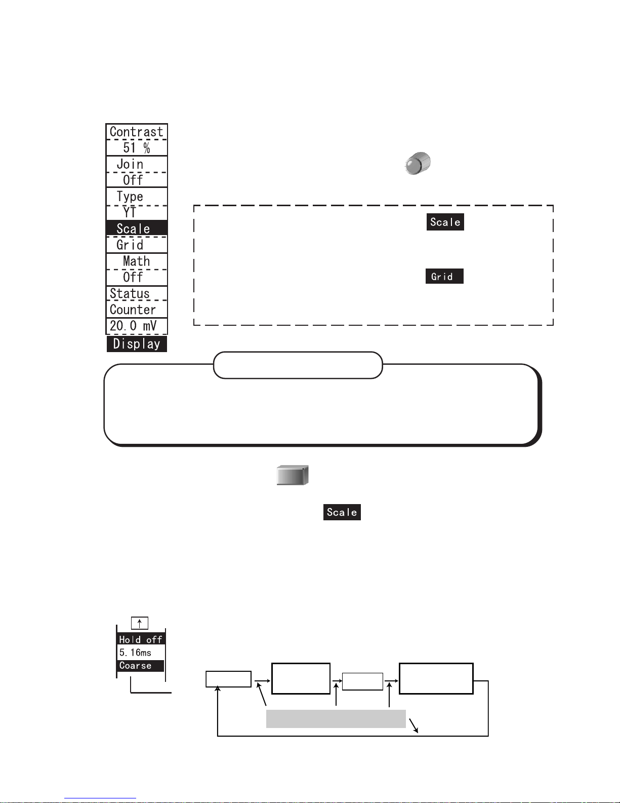
[Example] Set “Scale” to “Grid” in the Display menu.
(1) Selection method with FUNCTION
1. Press the DISPLAY button to show the display menu.
2. Turn the FUNCTION knob to select .
3. Press the FUNCTION knob to fix the menu item.
The setting item is displayed in reverse video.
4. Turn the FUNCTION knob to select .
5. Press the FUNCTION knob to fix the setting item.
The selected menu item is displayed in reverse video.
Menu (FUNCTION) operation
(2) Selection method with MENU
1. Press the DISPLAY button to show the display menu.
2. Turn the FUNCTION knob to select .
3. Pressing the DISPLAY button selects Frame, Grid or Axes.
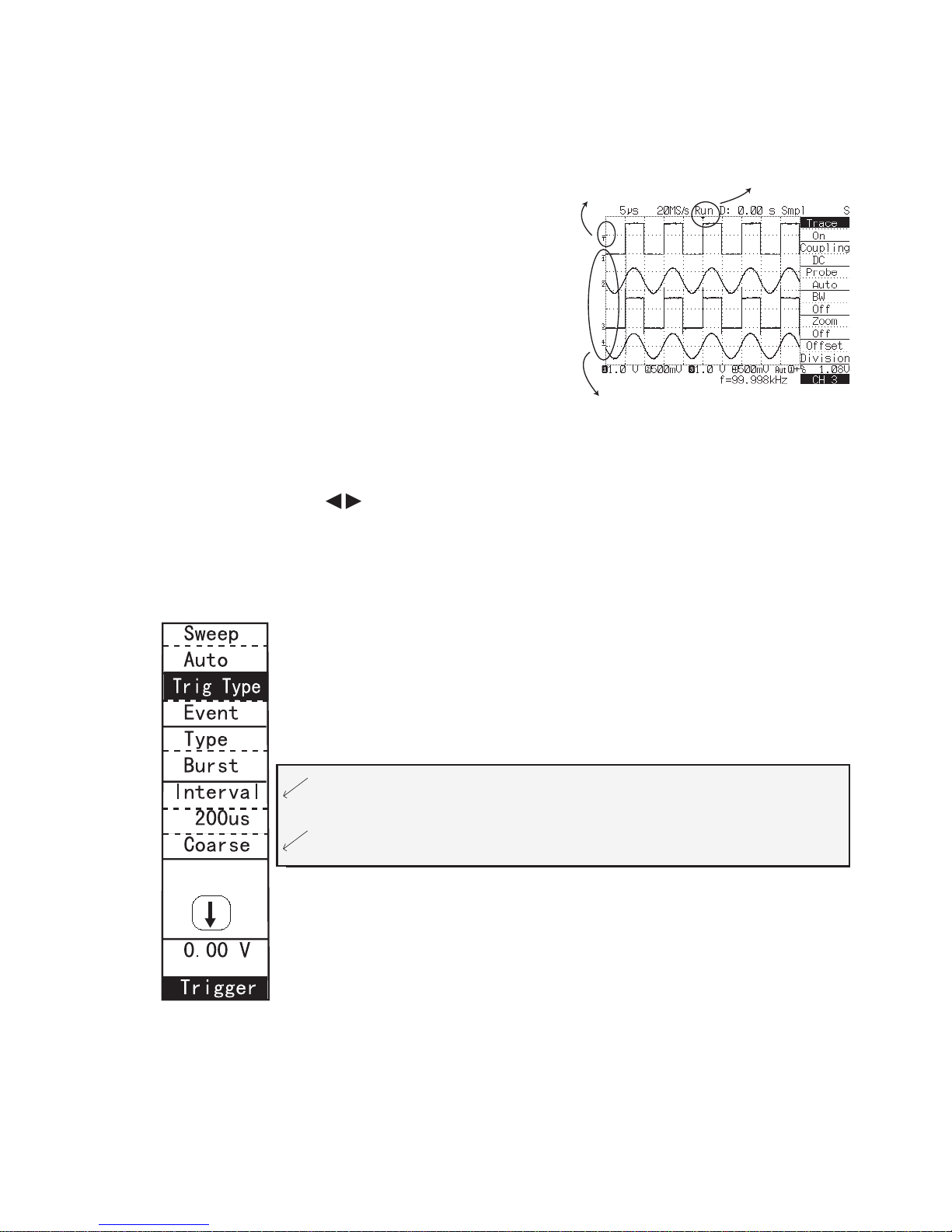
Setting a numerical value
There are two ways of selecting a setting item in the menu; one is to turn the FUNCTION
knob to select an item, and then press the knob to fix it, and the other is to fix the item
by pressing the menu button while the item is displayed.
Set the numerical value of Hold off in the trigger menu, Interval of
Event trigger or Line of TV as follows:
For the setting of File No. in SAVE/RECALL, Copy menu, see pages
36 to 39.
← Tthe numerical value steps, in rough or fine steps, are changed as
the following figure.
From the following explanations, (a series of operations 2 to 5 enclosed with
dotted line above) is expressed as follows:
Through [FUNCTION operation], set Scale menu to Grid.
Bear in mind!!
Hold off
Fine value
settable
Coarse
Coarse value
settable
Pressing FUNCTION knob
6
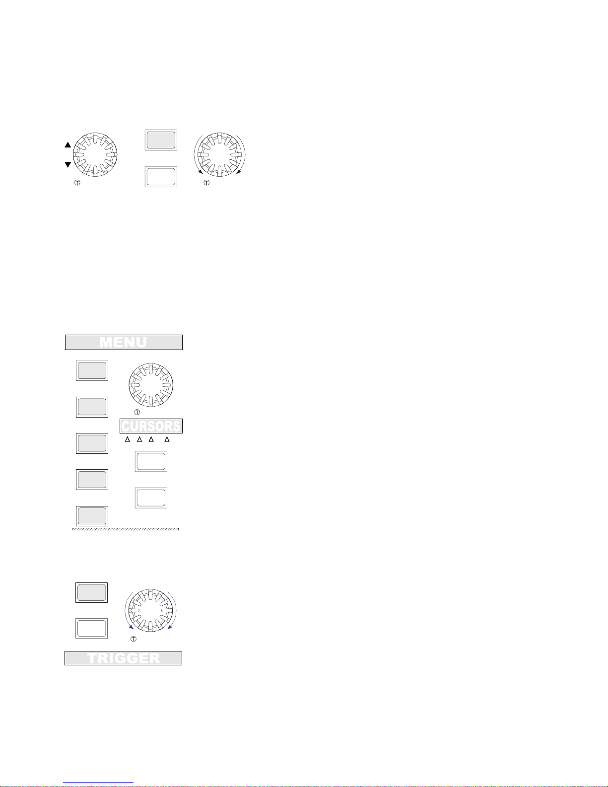
[MENU] button: Displays the ACQUISITION, DISPLAY,
MEASURE, SAVE/RECALL and UTILITIES menus.
[FUNCTION] knob: Selects and fixes an item on the menu
screen and controls the V/H cursor position during cursor
measurement. (P5)
[∆V/∆t/∆V& ∆t/V at t/ Off] button: Selects the cursor
measurement item from ∆V → ∆t → ∆V/∆t → V at t →
Off. The selected item is displayed at the top of the cursor
menu. (P22)
[C1/C2/TCK] button: Selects active cursors (C1, C2, or
tracking) to be moved by the FUNCTION knob C1;
Reference cursor, C2; Difference. (P22)
[TRIG MENU] button: Displays the TRIGGER menu. (P18)
[TRIG LEVEL] knob: Sets the trigger level. (P18)
[AUTO/NORM/SGL] button: Selects the sweep mode from
Auto → Normal → Single. (P20)
Description of operation section
Shown in ( ) is the reference page.
[MENU] button: Displays the CH1,CH2, CH3
and CH4 menus. (P14, P15, P44, P45)
[SELECT] button: Every time the SELECT
button is pressed, the channel to be operated
with CH1 and CH2 or CH3 and CH4 is
changed. (P14)
[OFFSET] knob: Sets the vertical position of a
trace. (P14)
[VOL TS/DIV] knob: Continuously selects the deflection factor in 1-2-5 sequence or ´1 to
´2.5 zoom as fine adjustment of the vertical gain sensitivity. Pressing the knob switches
between 1-2-5 sequence and zoom. (P14)
ENTER
ACQUISITION
FUNCTION
DISPLAY
MEASURE
SAVE/RECALL
UTILITIES
v/ t/ v& t
/v at t/OFF
C1/C2/TCK
-+
TRIG LEVEL
COARSE
MENU
AUTO/NORM/SGL
OFFSET
MENU
VmV
SELECT
VOLTS/DIV
COARSE ZOOM
7
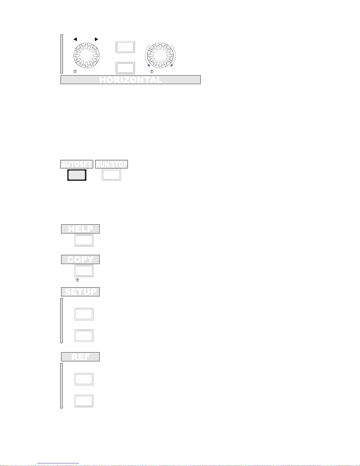
[HELP] button: Displays an explanation of the currently selected function.
(P10). In remote mode, all buttons and knobs on the front panel are
disabled except for the [HELP].
DELAY
PERSISTENCE
SLOW FAST
ZERO DELAY
TIME/DIV
COARSE COARSE
[DELAY] knob: Sets the trigger delay
time. (P16)
[ZERO DELAY] button: Set the trigger
delay time to zero. (P16)
[AUTOSET] button: Automatically sets the vertical, horizontal
and trigger condition to show the input signal. (P12)
[PERSISTENCE] button: Sets overwrite ON or OFF. When ON, waveforms are
accumulated on the display. (P17)
[TIME/DIV] knob: Selects the sweep rate in 1-2-5 sequence. (P16)
When pressing this knob while FFT is being selected in the Display-Math menu, the
screen is changed to the FFT screen or YT/XY screen.
SAVE
(LOCAL)
FEED
UNDO
SAVE
CLEAR
[RUN/STOP] button: Sets capturing a new signal or stops capturing. The selected
condition is displayed at the top right of the screen. (P21)
[COPY] button: Outputs a hardcopy of the screen or setup condition to a
specified output device. (P24)
SETUP [SAVE] button: Saves the current setup to the internal memory.
(P26)
SETUP [UNDO] button: Recalls the saved setup from the internal memory.
Pressing the button again undoes the recalling and returns to the previous
setup. (P26)
REF [SA VE] button : Saves the waveform data displayed on the screen to
the internal memory as a reference waveform. (P27)
REF [CLEAR] button: Displays the reference menu. Pressing the button
again erases all displayed reference waveforms. (P27)
8
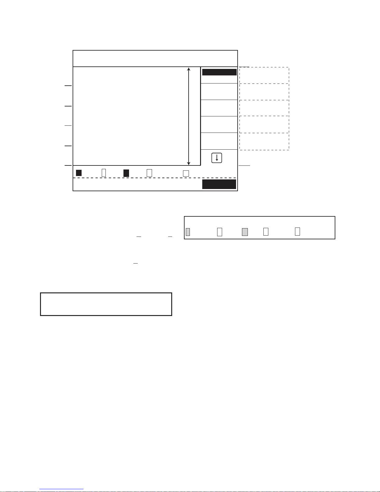
How to read screen
④④
④④
④ Vertical axis/trigger display area
h: Trace ON/OFF (when ON, displayed
in reverse video)
i: VOLTS/div
j: Operation setting
(addition (Add) = +,
subtraction (Sub) = –,
multiplication (Mult) = ×)
k: Sweep mode
l: Trigger source
m: Trigger slope/trigger coupling
n: Trigger level
⑤⑤
⑤⑤
⑤ Message status display area
Displays a selected status, temporary
message or alarm.
The selected menu to the right is displayed
in reverse video.
Displays ‘Remote’ during remote control.
①①
①①
① Waveform display area
Displays a waveform and scale.
At the left end of the screen, the GND
reference markers of CH1 to CH4
waveforms are displayed as markers 1 to
4, respectively. Additionally, the trigger
level is displayed as marker T.
②②
②②
② Horizontal axis and acquisition display
area
a: Timebase Time/div
b: Sampling rate
c: Run/Stop state
d: Delay time
e: Acquisition mode
f: Roll/equal sampling
g: Memory Length Short/long
When persistence is on, displayed in
reverse video.
③③
③③
③ Menu display area
Displays the selected menu.
Displays a cursor measuring item during
cursor measurement and displays a
interface menu during remote control.
a b cd efg
200ns 400MS/s Run D:-99.0ns Smpl Equ S/L
h i j k lmn
1 200mV + 2200mV 3 200mV 4 200mVAut 2 +HF ‑99.9mV
ޓ%QPVTCUV
%QPVTCUV
,QKP
,QKP
1HH
1HH
6[RG
6[RG
;6
;6
5ECNG
5ECNG
)TKF
)TKF
/CVJ
/CVJ
#FF
#FF
O8O8
O8O8
O8O8#WV
O8O8#WV
*(4
*(4
O8!
O8!
HM*\
HM*\
ޓ&KURNC[
&KURNC[
Ԙ9CXGHQTOFKURNC[CTGC
9CXGHQTOFKURNC[CTGC
Ԛ
ԛ
Ԝ
ԙ
㨪
PU/5U4WP&PU5ORN'SW
PU/5U4WP&PU5ORN'SW
5
VQ
1P
:;
#ZKU(TCOG
1HH5WD/WNV((6
6
6
9
GND: Reference mark display
Indicates the GND position with ‘_’. Up/down
arrows ▲ or ▼are displayed at the upper or
lower position when the channel position is
outside of the display area.
Trigger level mark display
Indicates the trigger position with ‘T’ when
the trigger coupling is DC or HF-REJ.
Up/down arrows ▲or ▼are displayed at the
upper or lower position when the trigger delay
position is outside the display area.
Delay mark display
Indicates the trigger position with ‘ ▼’.
Right or left arrows
▲▼
are displayed when the trigger position is outside the display
area.
← Menu item: Displays the selection status in reverse video.
← Menu setting: Displays the current setting. If the setting is selected
in [FUNCTION operation], it is displayed in reverse video.
Understanding the menu structure
Numerical value setting menu
Press the FUNCTION knob at this position to change the
numerical value one by one.
Press the FUNCTION knob at this position to change the
numerical value in rough steps.
← Indicates that there are more items below.
← Shows the menu displayed in the menu display area.
Marks on waveform display
Trigger level mark
CH1㨪CH4 GND Reference mark
Delay mark

10
Setting of date
The date is used for time display but also for the time stamp when saving a file and
capturing a waveform.
1. Select Date in the UTILITIES menu with [FUNCTION operation].
2. Press the FUNCTION knob to show the Date menu.
3. Select Month from 1 to 12 with [FUNCTION operation].
Set Day, Year, Hour and Minute in the same way.
The seconds are set to zero when fixing the date menu.
Before starting the measurement
Make the following adjustments if necessary.
Contrast setting
Adjusts the contrast of the screen.
The contrast is automatically set initially when the power is turned on. You may adjust
the contrast manually if necessary.
This manually-adjusted condition is maintained until the power is turned off.
1. Press the DISPLAY button to show the Display menu.
2. Adjust Contrast between 0 and 100% with [FUNCTION operation] to get the
appropriate screen brightness.
Selection of language
Selects the HELP language.
1. Select Config in the UTILITIES menu with [FUNCTION operation].
2. Press the FUNCTION knob to show the Config menu.
3. Select Language in the Language menu with [FUNCTION operation].
Press the HELP button at the top left. An explanation of the last operated function
is displayed.
HELP is canceled by any operation.
HELP function

11
How to restore the setting at time of purchase
1. Through [FUNCTION operation], set the SAVE/RECALL menu to DEFAULT.
2. Pressing the FUNCTION knob shows a message "Push the FUNCTION to go
on".
3. Pressing the FUNCTION knob again returns the panel setting (readout and part
of menu) to the factory setting.
Copy-related or interface-related settings, etc. are not changed (see Document 4).
Reverse display function (LCD)
Toggles the screen between Normal (white background) and Reverse (blue
background).
This function affects only the LCD display and does not affect the copy output.
1. Select Config in the UTILITIES menu with [FUNCTION operation].
2. Press the FUNCTION knob to display the Config menu.
3. Set the LCD menu to Normal or Reverse with [FUNCTION operation].
Display date on the screen
To display the date in the message area, select Date in the Status menu.
1. Press the DISPLAY button.
2. Select Date in the Status menu with [FUNCTION operation].
3. The date is displayed at the bottom right of the screen.
 Loading...