

Iwatsu IX-12KTS-3, IX-12KTD-3, Omega-Phone ADIX-VS, VS-KSU, VS-PWSU Owner's Manual
...
Owner’s Manual
SOFTWARE VERSION 7.30

SPECIAL NOTICE
CONVERSA TIO N RECO RDI N G
In certain states it is illegal to intercept and/or record telephone calls.
of listenin g in and /o r recording telepho ne calls. Because such activ ity is not illegal in all
jurisdictions and may be permitted in training and/or monitoring of personnel, this telephone system
can be programmed to permit interception and/or recording with or without warning to those on the
line. Before utilizin g th e system for such purposes, you are advised to consult with an attorney
familiar with laws of th e jurisdiction in whic h you utilize such feature.
make no representations with respe ct to the legality of its use and disclaim any liability for claims
and/or damages arising from the use or misuse of this feature.
TOLL RESTRICTION
The Toll Restriction feature of the ADIX-VS system is one method of preventing fraud (i.e., the
making of unauthorized toll calls) by users of the system. The chance of fraud may be reduced but
may not be eliminated. Therefore, no expressed or implied warranty is made against fraud. Only a
complete p rog ram which includes b ut may no t b e limited to inspection of telephone call billin g , use
of call detail recorde rs and o th er such devices, systematic monitoring of all tele p h o n e call activity,
and implementing corrective m easures can minimize the poss ib ility o f fraud. Consult with your
Authorized Iwatsu Ame ric a Distributor fo r further details or assistance in the event you are
experiencing unauthorized toll calls.
All brand names and product names used in this manual are trademarks of their respective
companies.
Iwatsu America, Inc., 8001 Jetstar Dri ve, Irving, TX 75063, (972) 929-0242
Email: in fo@i wa tsu.com, Web : www.i watsu. com
© 2002 by Iwatsu America, Inc.
All rights reserved.
In certain states and under certain circumstances it is illegal to intercept f o r th e purposes
Iwatsu America, Inc., its distributors, and the manufacturers responsible for this feature
Software Version 7.30 Edition September 2002
Printed in the United States of America
All rights are reserved. No part of this manual or accompanying software may be
reproduced, in any form or any means, without the permission of Iwatsu America,
Inc.
This manual was written for ADIX-VS systems with version 7.30 software. In some
cases, available feature operations may differ from those listed in this manual,
depending on the hardware, software and programmed functions in your ADIX-VS
system. For more information contact your Authorized Iwatsu Distributor.
Iwatsu America, Inc. has used its best effort to ensure that the information in this
manual was accurate at the time of printing. Iwatsu America, Inc. makes no
warranty of any kind, expressed or implied, with regard to the contents of this
manual. This information is subject to change without notice.
Iwatsu America, Inc. shall not be held responsible for any representation made
regarding this information by any individual.
Part Number : 108322

Contents
SECTION 1 – ADIX-VS GENERAL DESCRIPTION.......................1
FCC Registration and Requirements.....................................3
ADIX-VS System Components Overview...............................8
Components............................................................................... 8
ADIX-VS Hardware Capacities................................................ 10
Key Telephone Lamp Indications............................................. 11
Station Port Requirements........................................................ 11
Time Parameters...................................................................... 11
System Numbering Plan........................................................... 11
ADIX-VS Digital Telephones.................................................12
IX-12KTS-3 Digital Key Telephone ......................................... 12
IX-12KTS-3 Digital Key Display Telephone ............................ 13
IX-12KTS-2 Digital Multiline Telephones (Discontinued) ....... 13
IX-12KTD-2 Digital Multiline Telephones............................... 14
IX-MKT Digital Key Telephone............................................... 15
DCKT970 Digital Wireless Key Telephone.............................. 16
IX-DCKT900 Digital Wireless Key Telephone (Discontinued). 17
Digital Doorphones.................................................................. 17
Single Line Telephones ............................................................ 17
ADIX-VS Digital Telephone Key Functions .........................18
Optional Station Equipment.................................................20
IX-COMLINK-2...................................................................... 20
IX-KTLCD-3 Display Unit (IX-12KTD / S-3 only).................. 20
IX-12ELK-3 (IX-12KTD / S-3 only) ........................................ 20
IX-LRAU (IX-12KTD / S-3 only)............................................. 20
IX-12ELK Key Telephone Expansion Module.......................... 21
IX-SNHD Station Noise Canceling Handset............................. 21
IX-SHHD Station Amplified Handset....................................... 21
IX-BPCU (IX-12KTD / S-3 only)............................................. 21
IX-LRSP Station Loud-Ringer/ External Speakerphone Adapter21
IX-AUTD Auto-Dialer Unit ..................................................... 21
IX-BPAD Busy Bypass/Auto-Dialer Unit.................................. 21
IX-STPD Station Pedestal........................................................ 22
IX-VTPD IX-MKT / Versa-Phone Pedestal.............................. 22
IX-ADPD Autodial Pedestal ..................................................... 22
IX-SREP Star Repeater ............................................................ 22
Component Description .......................................................23
i

VS-PWSU Power Supply Description....................................... 23
VS-MAIN Motherboard Interface Card .................................... 23
VS-CPUMEM Common Control Card...................................... 23
System Port Interface Cards ................................................25
VS-4PSUB Digital Station Interface Card ................................ 25
VS-VML Omega-Voice VMI Card........................................... 25
VS-2CITK Caller ID Trunk Interface Card .............................. 25
VS-ICOTB ISDN BRI Line Interface Card............................... 26
VS-MISC Miscellaneous Function Card................................... 26
IX-IPSEGWAY Serial to Ethernet Gateway ..........................27
SECTION 2 - ADIX-VS SYSTEM FEATURES.............................29
ADIX-VS System Features....................................................31
All Ring Hunt Group................................................................ 31
Alphanumeric Speed Dial By Name......................................... 31
ANI Alphanumeric ID.............................................................. 31
Automatic Number Identification (ANI) Trunks....................... 31
Automatic Relay Control.......................................................... 31
Background Music................................................................... 32
Caller ID Alphanumeric ID...................................................... 32
Caller ID / ANI / DNIS Number Storage.................................. 32
Call Forwarding....................................................................... 33
Caller ID Trunks...................................................................... 33
Conversation Recording........................................................... 33
Delayed Ringing....................................................................... 34
DNIS Alphanumeric ID............................................................ 34
Dialed Number Identification Service (DNIS) Trunks............... 34
Direct Inward Line................................................................... 34
Direct Inward Line - Hunt Group............................................. 35
Emergency 911 Service Using Area Routing ............................ 35
E-Response Help Call Feature.................................................. 35
External Paging........................................................................ 35
Flexible Ringing....................................................................... 35
Flexible Station Numbering...................................................... 36
Group Monitoring.................................................................... 36
Hunt Group Delayed Ringing................................................... 36
Internal Paging......................................................................... 36
ISDN Calling/Called Party Number Coding............................. 37
ISDN Lines.............................................................................. 37
ISDN BRI Caller Name ID....................................................... 37
IX-MKT Key Assignment........................................................ 37
Loud Bell Interface................................................................... 37
Master Hunt Group .................................................................. 38
ii

Monitor Improvements............................................................. 38
Music On Hold......................................................................... 38
Optimized Routing................................................................... 39
Paging...................................................................................... 39
Personal Ringing Tones............................................................ 39
Power Failure Memory Backup................................................. 40
Power Failure Backup System .................................................. 40
Quick Forward using the Hold/Quick Forward Key.................. 40
Remote Programming/Diagnostics........................................... 40
Station Coaching...................................................................... 40
SMDR...................................................................................... 41
Station Coaching...................................................................... 41
System Clock ........................................................................... 41
System Speed Dial.................................................................... 41
Text Messaging........................................................................ 42
Toll Restriction ........................................................................ 42
Tone / Pulse Dialing................................................................. 42
Trunk Interfaces....................................................................... 42
Uniform Call Distribution (UCD)............................................. 43
Voice Mail/Automated Attendant Integration........................... 43
SECTION 3 - DIGITAL TELEPHONE USER’S GUIDE................45
Digital Telephones – Basic Feature Operation ...................47
Making an Outgoing Call......................................................... 47
Receivin g an Incoming Ca l l ..................................................... 47
Making an Intercom Call ......................................................... 48
Receivin g an Intercom Cal l ...................................................... 48
Making an E-Response Help Call............................................. 48
Transferring a Call to Another Extension................................. 49
Putting a Call On Hold............................................................. 50
Picking Up a Call On Hold....................................................... 50
Putting a Call On Call Park...................................................... 50
Handling a Second Call............................................................ 51
Digital Doorphone Operation ................................................... 52
Digital Telephones - Advanced Features ............................ 53
Caller ID, ANI, DNIS Information Storage .............................. 53
Absence Message Display......................................................... 54
Account Code........................................................................... 55
Alphanumeric Display.............................................................. 55
Alphanumeric Speed Dial by Name.......................................... 56
Alternate Tone/Pulse Dialing................................................... 57
Autodial Unit........................................................................... 57
Automatic Outside Line Answer / Hold.................................... 57
iii

Automatic Repeat Dialing ........................................................ 58
Background Music................................................................... 59
Barge-In ................................................................................... 59
Built-In Speakerphone.............................................................. 60
Busy Bypass/Autodial Unit....................................................... 60
Busy Bypass Tone Calling........................................................ 61
Busy Bypass Voice Calling....................................................... 61
Busy Intercom Callback............................................................ 62
Busy Number Callback............................................................. 63
Busy Outside Line Queuing...................................................... 64
Busy Overriding....................................................................... 65
Call Coverage........................................................................... 66
Call Forwarding....................................................................... 67
Call Monitoring ....................................................................... 68
Call Park/Swap ........................................................................ 69
Call Pick-Up............................................................................ 69
Direct Call Pick-Up.................................................................. 70
Internal Group Call Pick-Up.....................................................70
External Group Call Pick-Up.................................................... 70
Caller ID Display Change ........................................................ 71
Camp-On................................................................................. 71
Clear Call................................................................................. 72
Conference............................................................................... 72
Consultation Hold.................................................................... 73
Conversation Recording........................................................... 74
Delayed Ringing....................................................................... 75
Direct Outside Line Appearance............................................... 75
Direct Station Selection/Busy Lamp Field................................. 75
Distinctive Ringing - Outside Line Calls.................................. 75
Distinctive Ringing - ICM/Outside Line................................... 75
Do Not Disturb (DND) ............................................................. 76
Exclusive Hold......................................................................... 76
Executive Override................................................................... 76
Extension Number Display....................................................... 77
Feature Button Display............................................................. 77
Flash........................................................................................ 77
Floating Outside Line Group Access......................................... 78
Forced/Verified Account Code.................................................. 78
Full/Half Duplex Speakerphone Mode Switching ..................... 79
Group Monitoring.................................................................... 79
Group Park............................................................................... 79
Hands-Free Answerback On Intercom...................................... 80
Headset Button......................................................................... 80
iv

Headset Control Key................................................................. 80
Headset Connection.................................................................. 82
Hot Line................................................................................... 82
Howler Tone ............................................................................ 83
Last Number Redial.................................................................. 83
Master Hunt Groups ................................................................. 83
Memo Dial............................................................................... 84
Message Waiting...................................................................... 85
Microphone Cut-Off................................................................. 86
Monitor Improvements............................................................. 87
Off-Hook Outgoing Call........................................................... 87
Off-Hook Outside Line Answering ........................................... 87
Off-Hook Outside Line Queuing............................................... 88
On-Hook Dialing...................................................................... 88
Outside Line Call Restriction ................................................... 88
Outside Line Pick-Up Restriction ............................................. 88
Paging...................................................................................... 88
Personal Ringing Tone............................................................. 90
Preset Dial/Backspace Dialing.................................................. 90
Pri me Line A cces s.................................................................... 91
Privacy/Privacy Release............................................................ 91
Private Line.............................................................................. 91
Protected Station...................................................................... 92
Quick Mode Operation............................................................. 92
Remote Relay Control .............................................................. 92
Ring Muting............................................................................. 92
Save Number Redial................................................................. 93
Shift Call..................................................................................93
Speed Dial................................................................................ 94
Station Coaching...................................................................... 98
Station External Ringer Connection ......................................... 98
Station Restriction Password .................................................... 99
Text Messaging.......................................................................100
Time Reminder.......................................................................103
Tone/Voice Calling.................................................................104
Transfer Off Premise...............................................................104
Transfer to Guest Mailbox.......................................................104
Unanswered Incoming Outside Line Warning Tone ................105
Universal Night Answer..........................................................105
Voice Mail Message................................................................105
Voice Mail Monitor (Answering Machine Emulation).............105
Whisper Page..........................................................................107
Whisper Page During Consultation Hold.................................108
v

SECTION 4 - ATTENDANT POSITION FEATURES .................111
Attendant Position - Basic Features..................................113
Receivin g an Incoming Ca l l ....................................................113
Transferring a Call to Another Extension................................113
Transferring a Second Call to an Extension.............................113
Receivin g an Intercom Cal l .....................................................114
Putting a Call on Hold.............................................................114
Picking Up a Call on Hold.......................................................114
Putting a Call on Call Park......................................................114
Answering a Call that Returns to the Attendant Position.........115
Making an Outgoing Call........................................................115
Making an Intercom Call ........................................................115
Making an E-Response Help Call............................................115
Making a Page Announcement................................................116
Attendant Position - Advanced Features...........................117
911 Call Indication..................................................................117
Caller ID, ANI, DNIS Storage - Delete All.............................117
Alarm Clear............................................................................117
Attendant Automatic Hold.......................................................117
Attendant Override..................................................................118
Automatic Answer Mode.........................................................118
Clock Set/Adjustment..............................................................119
Direct Station Selection ...........................................................119
Incoming Call Termination.....................................................120
Flexible Call Forward (Internal/ External)...............................120
Night Mode.............................................................................122
Operator Priority.....................................................................122
Overflow Transfer...................................................................123
System Speed Dial Registration...............................................123
System Text Message Registration...........................................123
SECTION 5 - SINGLE-LINE TELEPHONE USER’S GUIDE...... 125
Single-Line Telephone - Basic Features ...........................127
Making an Outgoing Call........................................................127
Receivin g an Incoming Ca l l ....................................................127
Making an Intercom Call ........................................................127
Receivin g an Intercom Cal l .....................................................127
Making an E-Response Help Call............................................128
Transferring a Call to Another Extension................................128
Putting a Call on Hold.............................................................129
Picking Up a Call on Hold.......................................................129
Putting a Call on Call Park......................................................130
Handling a Second Call...........................................................131
vi

Single-Line Telephones - Advanced Features..................132
Account Code..........................................................................132
Busy Intercom Callback...........................................................132
Busy Number Callback............................................................133
Busy Outside Line Queuing.....................................................134
Call Forwarding......................................................................135
Call Park/Swap .......................................................................137
Call Pick-Up...........................................................................138
Camp-On................................................................................139
Clear Call................................................................................139
Conference..............................................................................140
Consultation Hold...................................................................141
Do Not Disturb........................................................................141
Flash.......................................................................................142
Floating Outside Line Group Access........................................142
Flexible Call Forward..............................................................142
Forced/Verified Account Code.................................................143
Group Park..............................................................................144
Hot Line..................................................................................144
Howler Tone ...........................................................................144
Last Number Redial.................................................................144
Master Hunt Groups ................................................................145
Message Waiting.....................................................................145
Off-Hook Outgoing Call..........................................................146
Off-Hook Outside Line Queuing..............................................146
Paging.....................................................................................146
Pre-Ringing.............................................................................147
Private Line.............................................................................147
Protected Extension .................................................................147
Shift Call.................................................................................148
Single Line Message Waiting Stutter Dial Tone......................148
Speed Dial...............................................................................148
Station Restriction Password ...................................................150
Tone/Voice Calling.................................................................150
Unanswered Incoming Outside Line Warning Tone ................150
Universal Night Answer..........................................................150
SECTION 6 – OMEGA-VOICE VMI USER’S GUIDE..................151
Omega-Voice VMI Basic Features.....................................153
Mail box A cces s .......................................................................153
Transfer to Voice Mail............................................................154
Forward to Voice Mail ............................................................154
Mailbox Tutorial.....................................................................154
vii

Main User Menu.....................................................................155
Message Folder Menu .............................................................155
Make a Message for Another User...........................................155
User Options Menu - Mailbox Setup..................................156
Mailbox Name.........................................................................156
Mailbox Greeting Management...............................................157
Mailbox Pass Code..................................................................157
Distribution List Menu ............................................................157
Blocking and Forwarding Menu..............................................159
Time/Date Feature...................................................................161
Message Replay Order.............................................................161
viii

Section 1 –
ADIX-VS General
Description


FCC Registration and Requirements
INSTRUCTIONS TO USER
CONGRATULATIONS ....... You selected a telep hone system
manufactured by Iwatsu Electric Co., Ltd. that was designed to provide a
multitude of features with the reliability for which Iwatsu products are
famous. The O mega-Phone AD I X - VS Telephone System is register ed and
approved by the Federal Communications Commission (FCC) for direct
connection to your local telephone service. In accordance with FCC rules
and regulati ons r egarding telephone equipment, Iwatsu is requir ed to make
you aware of your rights and obligations regarding the use of this
equipmentSo we may fulfill our obligations, please take a moment to
carefully read the rules and regulations contained herein that apply to you.
FCC RULES AND REGULATIONS
(1) Notification to the Local Telephone Company
The local Telephone Company may request specific information about the
Omega - P hone ADI X - V S Teleph one System before connect ion can be mad e
to the local Telephone Company lines. When requested by the Telephone
Company, the following information should be provided:
(a) The F C C Reg istr ation Number for all equipm ent con nected to an
individual line.
(b) T he largest Ri nger Equiva lence Number (RE N) for each line.
(c) Information required for compatible operation of the equipment with
the Telephone Company communication facilities.
The F C C Reg istr ation Number and Ri nger Equiva lence Nu mber (REN ) are
printed on the equipment label located on the common equipment cabinet of
the s ystem. The largest Ri nger Equiva lence Nu mber is the sum of the
Ring er Equ ivalen ce N u mber (RE N) of each FC C registered d evice that is
connected to the same line. The maximum Ringer Equivalence Number
that can normally be used without causing faulty operation is 5.0. Check
with your local Telephone Company to determine the maximum Ringer
Equivalence Number for the telephone lines you are using. In order to
connect registered terminal equipment to the Telephone Company lines, the
terminal equipment must utilize a FCC "standard means of connection,"
often referred to as a "registered jack. " The type of jack utilized on the
Omega-Phone ADIX-VS telephone system is identified by a USOC code
ADIX-VS General Description - 3

number. Different code numbers are utilized for the various types of
services p rovided by th e Telephone Company that the system s use. Wh en
requesting new telephone service, the Telephone Company must be
informed of the code nu mber for ea ch type of servi ce. Th e A DIX-VS system
can be configured as either a Key Telephon e System - Fully Protected , or a
Multi-Function (Hybrid)
System - Fu l ly Protected . Th e fol lowing a re the codes and reg istr ation
numbers applicable to the Omega-Phone ADIX-VS equipment:
ADIX-V S FCC Registration Numbers
Key Telephone S ystem - Fully Protected BD620Q-60444-KF-E
Multi-Function (Hybri d) S ystem BD6MLA-21244-MF-E
The following constitutes the other information required to be reported to
the local Telephone Company when requesting service:
CALLER ID / LOOP START TRUNK
Ringer Equivalence No.................0.5B
Service Order Code.......................9.0F
Facility Interface Code..................02LS2
Registered Connection...................RJ21X
ISDN BRI TRUNK
Service Order Code.......................6.0
Facility Interface Codes................ 02IS5
Registered Connection..................RJ49C *
NOTE: * — NT1 required.
(2) Restrictions on the Use of Registered Telephone Equipment
FCC r ules gover nin g customer owned t elephone equip ment specifically
exclud e the use of t he Omega-Phone ADIX- VS s ystem on public coin
telephone ( p ayphone) lines . Th e connect ion to party li ne ser vi ce is subject
to local state tariffs. Contact your state public utility, public service
commission, or corporate commission for more information.
(3) Incidence of Harm
If for some reason the Om eg a-Ph one ADIX-V S s ystem causes har m to the
Telephone Company network, the Telephone Company will notify you in
advance that temporary discontinuance of service may be required. In the
event advance notice is not practical, the Telephone Company will notify
you of the interruption of service as soon as possible. Also, the Telephone
Company will advise you of your right to file a complaint with the FCC if
you believe it is necessary. The Telephone Company may also make
changes in its facilities, operations, or procedures that could affect the
operation of your system. If this occurs, the Telephone Company will
provide advance notice in order for you to make the necessary modifications
to maintain uninterrupted service.
ADIX-VS General Description - 4

(4) Hearing-Aid Compatibility
The Omega-Phone ADIX-VS telephone system, utilizing telephone station
equip ment man u fa ctured by Iwat su, meet s all FC C requi rements for
Hearing-Aid compatibility.
(5) Instructi on Rega r ding the Repai r and Refurbishment of
Registered Equipment
Only the manufacturer or its authorized agents are permitted under the FCC
rules to make other than routine repairs to registered telephone equipment.
Repairs made to registered telephone equipment by unauthorized entities
will void equipment warranties as well as violate local state tariffs. Routine
repairs are classified typically as lam p replacement, fuse repla cem ent,
dir ectory label repla cement , etc. All other repairs to your Omega-P hone
ADIX-VS telephone equipment should be performed by Iwatsu America,
Inc. When trou bl e is experienced on an y telephone line th at your system i s
connected to and the trouble is causing harm to the network, the Telephone
Company may request that you remove the equipment from the telephone
line(s) until the problem has been corrected. To contact Iwatsu America,
Inc. for information regarding the repair of your equipment, write or call:
(201) 935-8580
IWATSU AMERICA, Inc.
70 Moonachie Avenue
Moonachie, NJ 07074
Attn: Repair Department
(6) Use of Other FCC Registered Equipment
Aside from the Ringer Eq uiva lenc e reporting as expla ined (above ), us e of
other FCC equipment may provide for specific limitations depending upon
the type of equipment. Check the instructions included with such
equipment to determine what the limitations are, if any, on the use of such
equipment.
(7) Automatic Dialers
The O mega-Phone AD I X - V S s ystem conta in features tha t provid e for th e
automatic dialing of outgoing calls. When programming Emergency
Numbers and (or) making test calls to Emergency Numbers:
(a) Remain on the line and briefly explain to the dispatcher the reason for
the call.
(b) Perform such activities in the off-peak hours such as early morning or
late evening.
ADIX-VS General Description - 5

(8) Toll Restriction and Optimized Routing Features
The Omega - Phone ADIX-VS system provides both T oll Restriction a nd
Optimized Routing features that may be programmed in your system. The
software or programming contained in the ADIX-VS system may be
required to be upgraded to allow user access to the network in order to
recognize newly establi s hed n etwork area codes and ex chan ge codes as t hey
are placed in service. Failure to upgrade the programming or software (if
required) to recognize the new codes as they are established will restrict the
user from gaining access to the network and to these codes. Bell
Communication Research (Bellcore) publishes North American Numbering
Plan ( NANP) i nformati on in pa p er, micr ofich e a nd tape. An abbreviated
summ ary of the newly established area cod es and ex change codes is also
available. Bellcore may be contacted at (973) 829-2000 or on the Internet at
www.be llc ore.com to obtain th e ap pro pr iate i nformation for keep in g current
with changes in the NANP.
(9) Radio Frequency Emissions
The O mega-Phone AD I X - V S Telephone System is register ed with the FCC
as a Class A RF Device that may radiate radio frequency emissions. In the
event t hat the system causes inter ference with anoth er device, steps m ust be
taken to r educe th e int erference, includ i ng possible removal of th e
equipment. While the probability of such an event is low, consult Iwatsu
Amer ica, I nc. for fu rther as sistance if this occurs.
(10) Equal Access Requirements
This system is capable of providing users access to interstate providers of
opera tor services through the use of equal access codes. Failure to provid e
equal access capabilities is a violation of the Telephone Operator Consumer
Services Improvement Act of 1990 and Part 68 of the FCC rules.
(11) Electrical Safety Advisory
While this system is fully compliant with FCC Rules and Regulations, it is
recomm ended t hat an AC s u rge arres t or of the form and capacity sui t able
for the model of system purchased be installed in the AC outlet to which the
system is connect ed . Consult wit h your di s tribu tor as to the surge p rotector
requirements for your system.
(12) Music-On-Hold
ADIX-VS General Description - 6

In accordance with U.S. Copyright Law, a license may be required from the
American Society of Composers, Authors and Publisher, or other similar
organization, if radio or TV broadcasts are transmitted through the musicon-hold feat u re of th e telecommu nica tion system. Iwat s u A merica, Inc.,
hereby disclaims any liability arising out of the failure to obtain such a
license.
(13) Use of Call Recorder and VM Record
In certain states it is illegal to intercept and/or record telephone calls. In
certain states and under certain circumstances it is illegal to intercept for
the purposes of listening in and/or recording telephone calls. Because such
activity is not illegal in all jurisdictions and may be permitted in training
and/or monitoring of personnel, this telephone system can be programmed
to permit interception and/or recording with or without warning to those on
the line. Before utilizing the system for such purposes, you are advised to
consult with an attorney familiar with laws of the jurisdiction in which you
utilize such feature. Iwatsu America, Inc., its distributors, and the
manufacturers responsible for this feature make no representations with
respect to the legality of its use and disclaim any liability for claims and/or
damages arising from the use or misuse of this feature.
(14) Emergency 911
ADIX-VS can be confi gured to use assi gned t elephone numbers (C aller ID
or ANI) for defined areas based on the proposed "40,000 sq. ft. rule." This
“Area Routing” feature provides the 911 Public Service Answering Point
(operator) information that identifies the general location of the caller.
IWATSU AMERICA, INC.
ADIX-VS General Description - 7

ADIX-VS System Components Overview
Components
VS-KSU Control Module
8 Card Slots
Dimensions (HxWxD): 13.8"x16.5"x5.9"
Weight: Approximately 14.5 lbs. fully loaded
VS-PWSU Power Supply
Dimensions (HxWxD): 2.5"x4.7"x8.3"
Weight: 4 lbs.
Switch P aramet ers
Time Division Multiplexed PCM32
Mu-law Speech Compress ion
Time Slots: 114
Stored Pr ogram
Distributed Multi-microprocessor
System Memory
Component Flash Memory
VS-CPUMEM 4 MB 2 MB
Heat Dissipation
VS-PWSU (maximum): 162 BTU/hr
Environment
Operating Tem p erat u re:
0° to 40°C/32° to 104°F
Storage Temperature:
-10° to 50°C/14° to 122°F
Relative Humidity (noncondensing):
10% to 90%
Power Nominal
VS-PWSU Input: 167 watts 240 watts
Maximum
RAM
AC Input
AC Input Voltage Tolerance:
VS-PWSU: 108V-132V @
120V
Frequ ency Toler ance:
VS-PWSU: 47 Hz -63 Hz
Maximum Input Current
VS-PWSU: 2.0 A
ADIX-VS Cabinet (VS-KSU)
ADIX-VS General Description - 8

Ringing Generator
Frequency: 20 Hz
Amplitude: 90 VAC
Maximum Simultaneous Ringing
(SLT): 2
Battery Backup
The ADIX-VS (V S-PWSU)
power supply includes a battery
interface. Backup time is
dependent upon battery array,
system size and system usa g e.
FCC Registration Number
KF: BD6MLA-21247-KF-E
MF: BD6MLA-21244-MF-E
Facility Interface Codes
Caller ID Trunks: 02LS2
ISDN BRI: 02IS5
Attendant Position
Maximum Attendant Positions:1
Telephone Requirements
Digital T e l ephones
Wiring: 1 pair
Total End-to-end Distance
22 AWG Twisted Pair: 1,000 ft.
24 AWG Twisted Pair:1,000
ft.
1 Star Repeater: 1,500 ft.
2 Star Repeaters: 8,000 ft.
Single Line Telephones
Wiring: 1 pair
Wiring w/Message Lamp: 1 or 2
pair
Maximum Loop Resistance
On-premise SLT: 600 ohm
Ringing Frequency: 20 Hz
Circuits Per Card
Digital Station Card (VS-
4PSUB):
4 circuits
Analog Station Ports (standard):
2 circuits
Omega-Voice VMI
(VS-VML): 4 circuits
Caller ID Trunk Card (VS-
2CITK): 2 circuits
ISDN BRI Trunk Card
(VS-ICOTB): 1 circuit
(2B + 1D)
Miscellaneous Function Card
(VS-MISC): 5 circuits
Software
Outgoing Trunk Groups: 10
Incoming Trunk Groups: 10
Incoming Call Ringing
Assignment:
16 Stations/Line.
Incoming Call Delayed Ringing
Assignment:
16 Stations/Line
Doorphone Ringing Assignment:
16 Stations/Doorphones
Call Pick-up Groups: 10
CO/ICM Hunt Groups: 10
Maximum Stations per Hunt
Group: 16
Paging Groups Internal: 8
Maximum Stations per Paging
Group: 16
External Paging Zones: 2
Station Speed Dial: 10
System Speed Dial: 90
Maximum Digits per Speed Dial
Number: 32
Speed Di al Alp hanumer ic ID:
10 characters
CO/Station Alphanumeric ID:
8 characters
ADIX-VS General Description - 9

Account Codes: 12 digits
Forced Verified A ccount Cod es: 80
Park Orbits
Attendant/System: 10
Station: 1
Call Forwarding:
No Answer: no limit
Station Numbering Plan:flexible
Station Text Messages: 10
System Text Messages: 90
Text Message Groups: 10
Maximum Stations per Text
Message Group: 16
Station Flexible Key Patterns:13
Caller ID/ANI/DNIS Tables:100
Caller ID Storage: 50 calls
ADIX-VS Hardware Capacities
SYSTEM1 ADIX-VS
Power Supply VS-PWSU
Card Slots 8
Number of Ports2 45
Trunk Ports3 6
Station Ports 16
Digital Station Ports 14
Voice Mail Ports 4
Attendant Positions 1
On-premise SLTs 2
Doorphones 14
Busy Byp a ss Un i t s4 7
Caller ID Trunks 6
Loop Start Trunks 6
Confer ence Circuits 2
ISDN BRI Cards3 3
Miscellaneous Function Ports 5
Serial Ports 2
1. This table lists the maximum quantity supported for each component
type. The combined total number of ports for each system is limited
to the “Number of Ports” category of this table. The capacities listed
are based on the total number of card slots available, software
restrictions and the power consumption of each component..
2. The combined number of Station, Trunk, and Miscellaneous ports
may not exceed the number of ports listed in this category.
3. The total number of trunks programmed may not exceed 6 Caller
ID/Loop Start Trunks or 3 ISDN BRI Lines.
4. When Busy Bypass Units are used, the total number of Digital
Stations may not exceed these numbers.
ADIX-VS General Description - 10

Key Telephone Lamp Indications
Status Lamp Indication
I-Use (Green)....................................... Modulation Steady (On)
CO Incoming/Call Forward.................. 0.1 sec. on, 0.9 sec. off
I-Hold (Green)..................................... 0.5 sec. on, 0.5 sec. modulated on
System Hold/Non-Privacy.................... 0.1 sec. off, 0.3 sec. modulated on
Recall, ICM Incoming, MSG ............... 0.7 sec. off, 0.3 sec. modulated on
DND.................................................... 0.5 sec. on, 0.5 sec. modulated on
Busy.....................................................Steady (On)
Station Port Requirements
Model Description Ports Required
IX-12KTS-3.......12 line keys (24 line keys with IX-12ELK-3)........... 1
IX-12KTD-3 ...... 12 line keys (24 line keys with IX-12ELK-3)........... 1
IX-12KTS-2.......12 line keys (24 line keys with IX-12ELK)..............1
IX-12KTD-2 ...... 12 line keys (24 line keys with IX-12ELK).............. 1
IX-VT................Versa-Phone............................................................ 1
IX-MKT ............ Digital Key Telephone............................................. 1
DCKT970 ......... Digital Wireless Telephone......................................1
or shared with
digital telephone
IX-DCKT900..... Digital Wireless Telephone......................................1
or shared with
digital telephone
IX-DDPH...........Digital Doorphone...................................................1
IX-BPAD........... Busy Bypass Unit for IX-12KTx-2 ........................... 1
Time Parameters
Hold Recall Timer................................0 - 255 seconds
Timed Trunk Queuing ......................... 1 - 20 minutes
Doorphone Answer Time..................... 5 - 255 seconds
Hunting Time...................................... 0 - 255 seconds
Night Mode Start Time ........................ 00:00 - 23:59
Auto CO Answer Start Time................ 00:00 - 23:59
MISC Relay Timer............................... 10 - 255 ms
System Numbering Plan
ADIX-VS has a Flexible numbering plan. Default numbering is three digits.
Station length can be changed to two, three, or four digits in length.
ADIX-VS General Description - 11
ADIX-VS Digital Telephones
There are seven types of Digital Key Telephones designed to work with
ADIX-VS. Each of these telephones is described in this section.
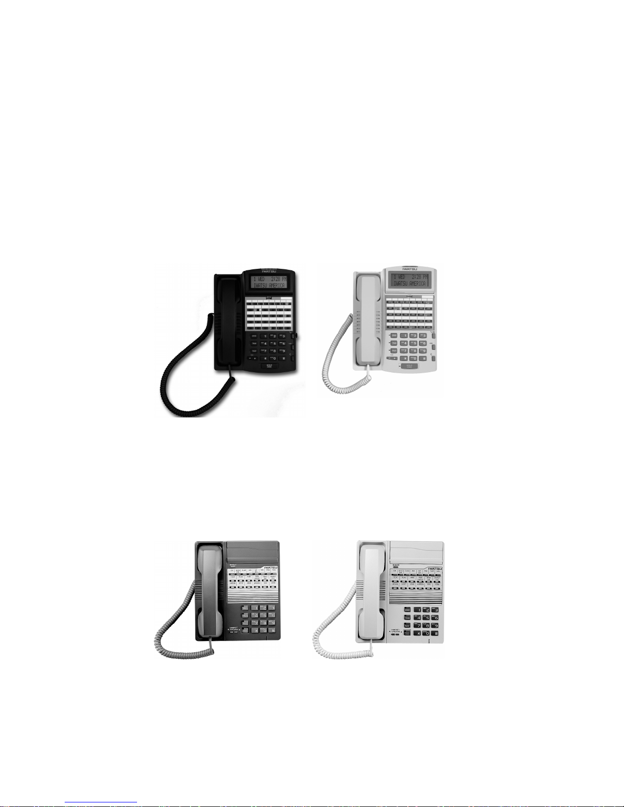
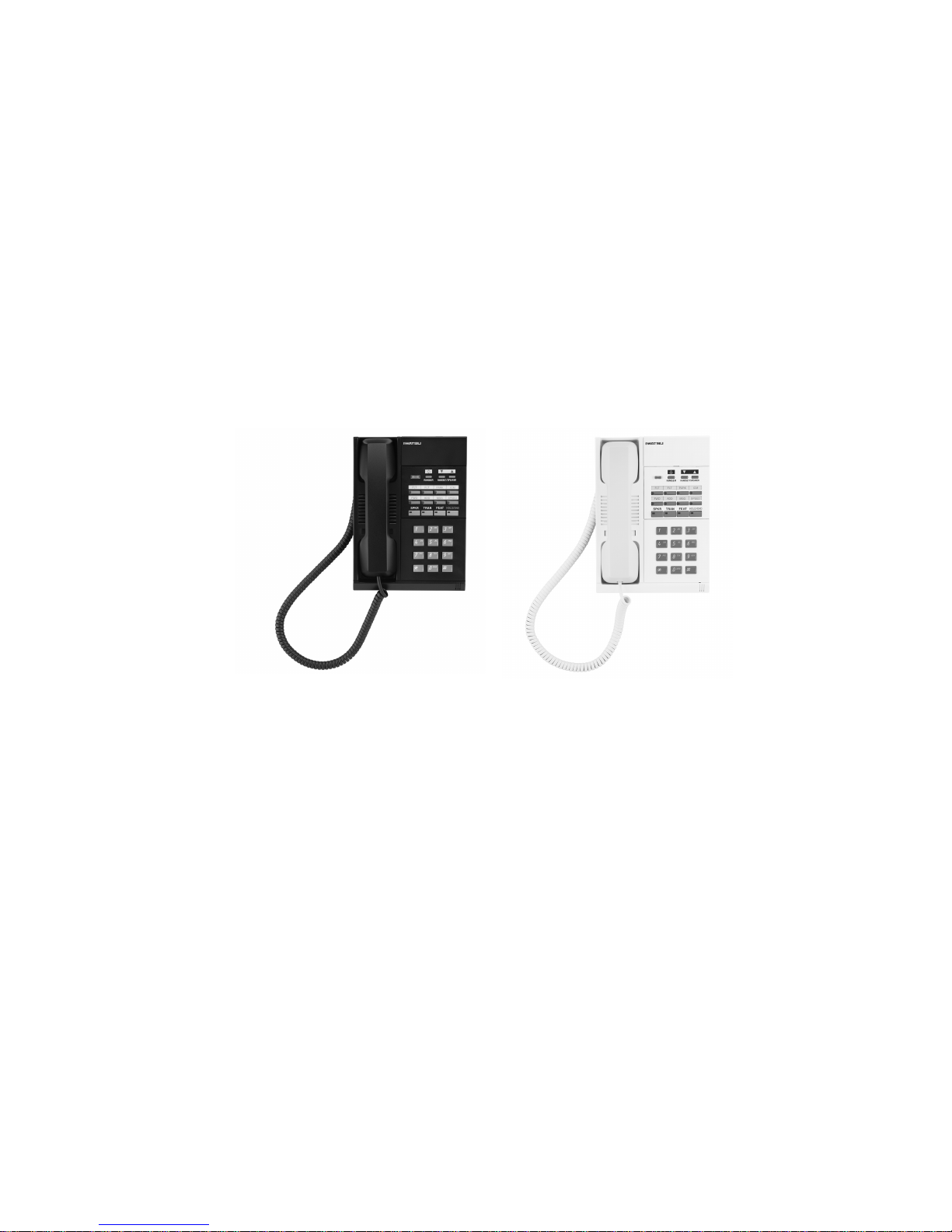
IX-12KTS-3 Digital Key Telephone
The IX-12KTS-3 Digital Key Telephone has 4 Fixed Feature Keys with a
red LED, 8 Programmable Multi-Purpose Keys with a red LED, 12
Programmable Multipurpose Keys each with a red LED and a gr een LED, a
mute k ey, a ringer volume con trol k ey, a handset volu me control key, a
speaker volume control and a full-duplex speakerphone. The IX-12KTS-3
Digital Key Telephone has an incoming call/message waiting indicator
lamp that flashes red for incoming calls and green for a programmable
feature such as message waiting. The IX-12KTS-3 may be enhanced by
adding the IX-12ELK-3 wh ich adds 12 programmable multi-purpose keys.
This model is available in black or white.
IX-12KTS-3 black and whi te
ADIX-VS General Description - 12
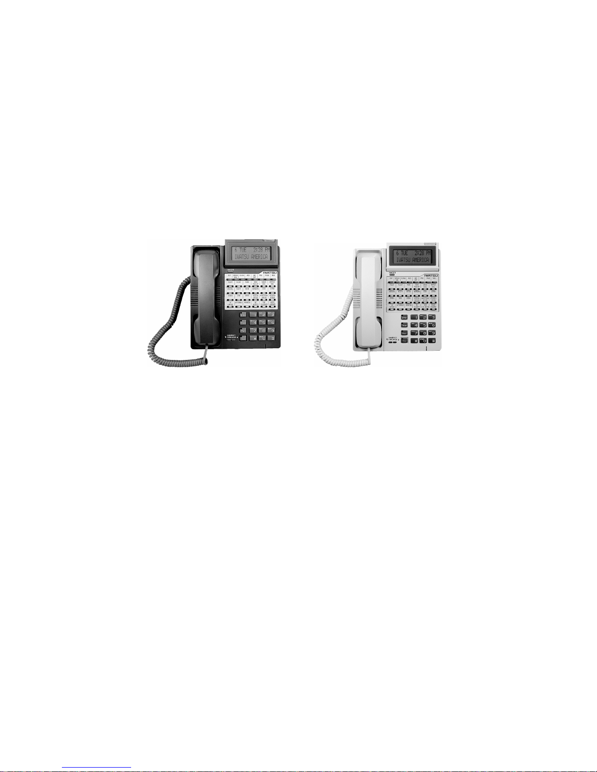
IX-12KTS-3 Digital Key Display Telephone
The IX-12KTD-3 Digital Key Display Telephone offers all the functionality
of the IX-12KTS-3 with the addition of a 2-line, 16 characters per line
liquid crystal display. This display is very helpful for using advanced
features and for providing status information. T he IX-12KTD-3 Digital Key
Telephone has an incoming call/message waitin g in dicator lamp that
flashes red for incoming calls and g reen for a prog rammable feature such as
message waiting. This model is available in black, or white.
IX-12KTD-3 with IX-12ELK-3, black and whi te
IX-12KTS-2 Digital Multiline Telephones
(Discontinued)
The IX-12KTS-2 Digital Multiline Telephone has four fixed feature keys,
eight feature keys with red LED’s and an additional 12 multipurpose keys
for feature operation or outside line appearances. Twelve multipurpose keys
may be added with the addition of an IX-12ELK key expansion module.
IX-12KTS-2, g ray and ash
ADIX-VS General Description - 13
IX-12KTD-2 Digital Multiline Telephones
The IX-12KTD-2 Digital Multiline Display Telephone offers all the
functionality of the IX-12KTS-2 with the addition of a 2-line, 16 characters
per line liquid crystal display and an incoming call indicator lamp. This
display is very helpful for using advan ced features and for providing status
information. The oversized indicator lamp flashes red for incoming calls
and green for a programmable feature such as message waiting.
IX-12KTD-2 with IX-12ELK, black (not shown), gray (discontinued) an d ash
(discontinued)
ADIX-VS General Description - 14
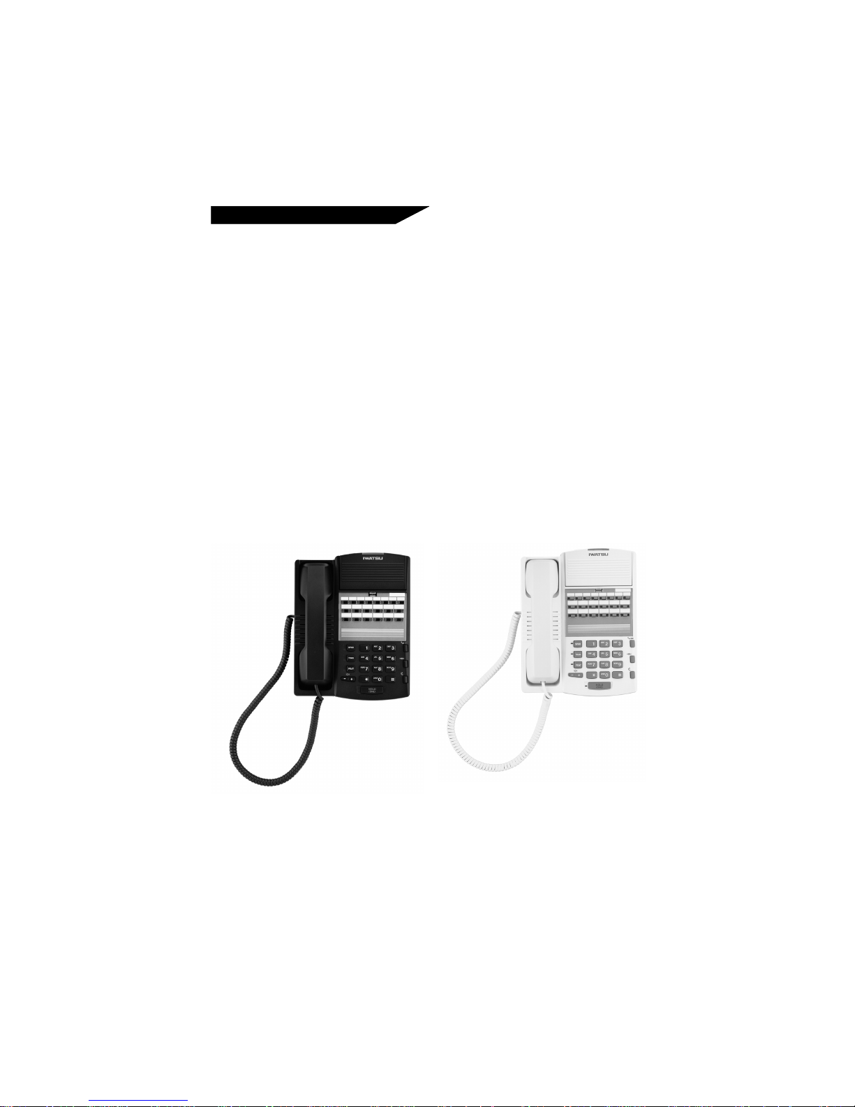
IX-MKT Digital Key Telephone
The IX-MKT Digital Key telephone is equipped with 4 Fixed Feature Keys
with a red LED and 8 Program m able Multipur pose Keys with a red/green
LED, and an incoming call indicator lamp that flashes red for incoming
calls and green for a programmable feature such as message waiting. The
IX-MKT may be upgraded with an optional internal speakerph one un it . In
addition, the IX-MKT also supports a single line/modem connection (for
outgoing calls only) through an in-board modular connector. This feature
allows simultaneous use of a modem while on a voice call. This model is
available in black or white.
IX-MKT, black and white
ADIX-VS General Description - 15
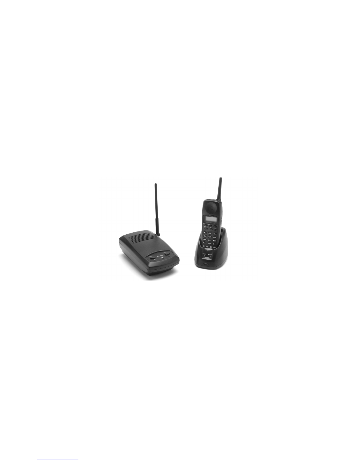
DCKT970 Digital Wireless Key Telephone
The DCKT970 Digital Wireless Key Telephone has four feature keys
(Transfer, Hold, Feature, Channel and Redial) an d four function (F1-F4)
keys. It may be connected directly to a digital station port, or it may shar e a
port with a digital telephone. All of the keys on this telephone are
programmable with the exception of the Talk, Channel and Redial keys
which are fixed. The transmission frequency of the DCKT970 is between
902 and 928 Mhz.
For operation instructions on the DCKT970 Digital Wireless Key
Telephone please refer to the DCKT970 Digital Wireless Key Telephone
Owner’s Manual (Part Number 109530).
DCKT970
ADIX-VS General Description - 16
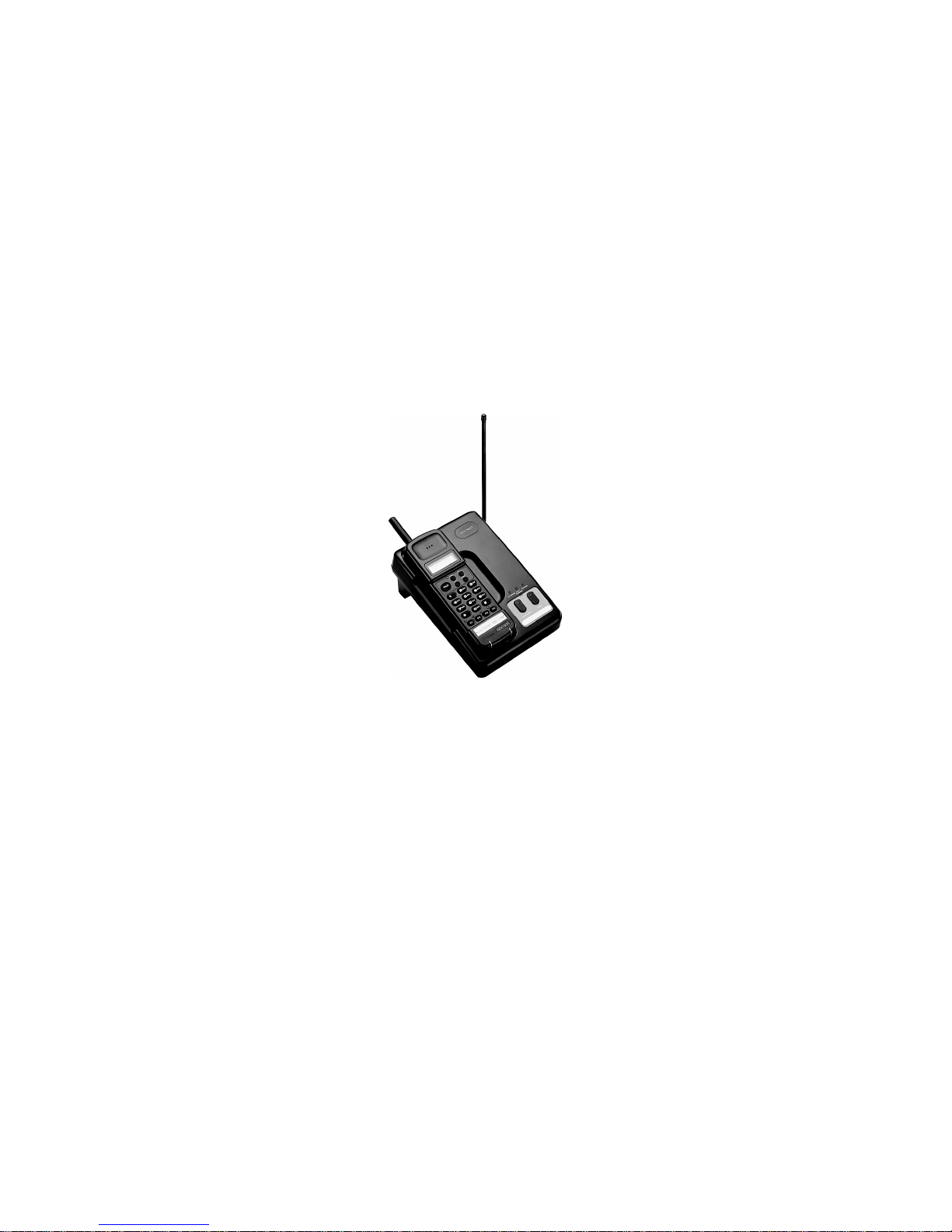
IX-DCKT900 Digital Wireless Key Telephone
(Discontinued)
The IX-DCKT900 Digital Wireless Key Telephone has four feature keys
(Transfer, Hold, Feature, and Memo) and four function (F1-F4) keys. It may
be connected directly to a digital station port, or it may share a port with a
digital telephone. All of the keys on this telephone are programmable with
the exception of the MEMO key which is fixed. The transmission frequency
of the IX-DCKT900 is between 902 and 928 MHz.
IX-DCKT900
Digital Doorphones
The Digital Doorphone (IX-DDPH) provides an economical and simple
method to allow visitors to make an intercom call to gain entrance to your
building.
Single Line Telephones
ADIX-VS will support two industry-standard 500 or 2500 type single line
telephones.
ADIX-VS General Description - 17
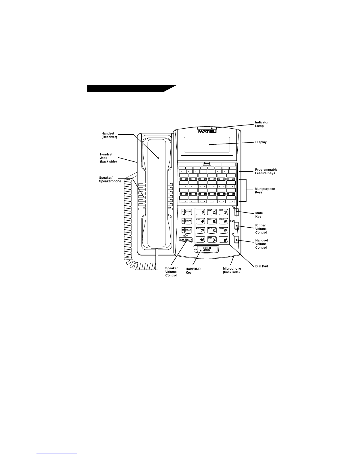
ADIX-VS Digital Telephone Key
Functions
ADIX Digital Telephone Key Layout
Multipurpose Keys - C an be progra mmed for a specific fu nction, such as
outside lines, individual extensions, or one-touch feature operation.
Button Lamps - Light up or flash when someone is using a line or a
feature corresponding to that button.
Green Lamp - Means that you are using that line.
Red Lamp - Means that someone else is using that line.
SPKR (Speaker) - Withou t lifting the receiver, the S p eaker button allows
you to dial and receive outs ide or i nternal call s , as well as conver s e, for
"ha nds-free operation ."
ADIX-VS General Description - 18

TRAN (Transfer) - Allows you to transfer a call from your telephone to
another extension.
FEAT (F eat ure) - The feature butt on is used to help op erate certa in special
and advanced features available through ADIX-VS.
HOLD/DND (Ho ld/Do Not Disturb) - This button is used to put a call on
Hold, to set the Do Not Disturb function to prevent any calls from getting
through or ringing at your extension or to transfer the call to the number set
in your Fixed Call Forward Destination.
Speaker Volume Control Button – The Speaker Volume Control is a
rocker switch with sixteen settings. To increase the speaker volume, press
the + side of the key; to decrease the volum e of the spea k er, press the - sid e
of the key. The Speaker Volume Control now controls only the speaker
volume, you can select the desired volume through thi s vari able control.
Ringer Volume Control - There are 4 vol u me levels t o chose from.
When a new volume level i s chosen, a tone sound s at the selected vol u me
level: one beep sounds for the lowest volume setting, four beeps sound at the
hig hest. This key also con trols the volu me of the BGM ( Ba ck g roun d M u s ic)
played on the telephone.
Handset Volume Control - The handset volume control buttons allow
you to adjust the handset volume and headset volume to one of three levels.
Mute - When you are usi ng the Speak erph one, Hands-Free Answerback or
the handset/headset, the Mute button prevents any voice or sounds to be
heard by the p erson on th e ot her end of your call. When you pr es s the Mu te
button to turn off the microphone, the Mute button will stay lit. Pressing
the Mute button again permits the other person to hear your voice again.
Man y ADIX-VS featu res can be opera ted either by dialing a feature
operation code or using a one-touch feature button, if your telephone has
one ass igned for that speci fi c feature. The feature code numbers listed in
this manual are preset in the ADIX-VS system. Your system installer may
assign a different code number for any feature based on individual system
requirements.
ADIX-VS General Description - 19

Optional Station Equipment
The following components provide the ADIX-VS station terminals with
additional features.
IX-COMLINK-2
IX-COMLINK-2 is a TAPI-compliant Computer Telephony Interface
adapter tha t bridges th e gap between your PC and ADIX-VS digital desktop
telephone. IX-COMLINK-2 combines desktop application software such as
Iwatsu’s Contact Point application and a digital telephone system to fully
harness the power of your PC through your ADIX-VS telephone system.
IX-KTLCD-3 Display Unit (IX-12KTD / S-3 only)
IX-KTLCD-3 units are avail-able in both black and white to match the IX12KTD / S-3 Digital Key Telephones. The IX-12KTS-3 Digital Key
Telephones are field upgrade-able to receive the new IX-KT LC D - 3 unit.
IX-12ELK-3 (IX-12KTD / S-3 only)
The IX-12ELK-3 Expansion Line Key units add an additional 12 keys to
your IX-12KTD / S-3 Digital Key Telephones and are available in both
black and white to match the IX-12KTD-3 and IX-12KTS-3 Digital Key
Telephones. The buttons on the black telephone are black, and the buttons
on the white phone are gray. The IX-12KTD / S-3 Digital Key Telephones
are field upgradeable to receive th e new IX-12 ELK-3.
IX-LRAU (IX-12KTD / S-3 only)
The IX-LRAU Internal Loud Ringer Unit provides the interface for IX12KTD-3 or IX-12KTS-3 Digital Key Telephone to a station loud-ringer,
exter nal s p eakerp hone unit and a recor d ing d evi ce. Th e I X - LRAU work s
the same as the IX-LRSP but provides a new interface to a recording device
through a 1 / 8 inch mini-jack audio connector.
ADIX-VS General Description - 20
 Loading...