

Page 1
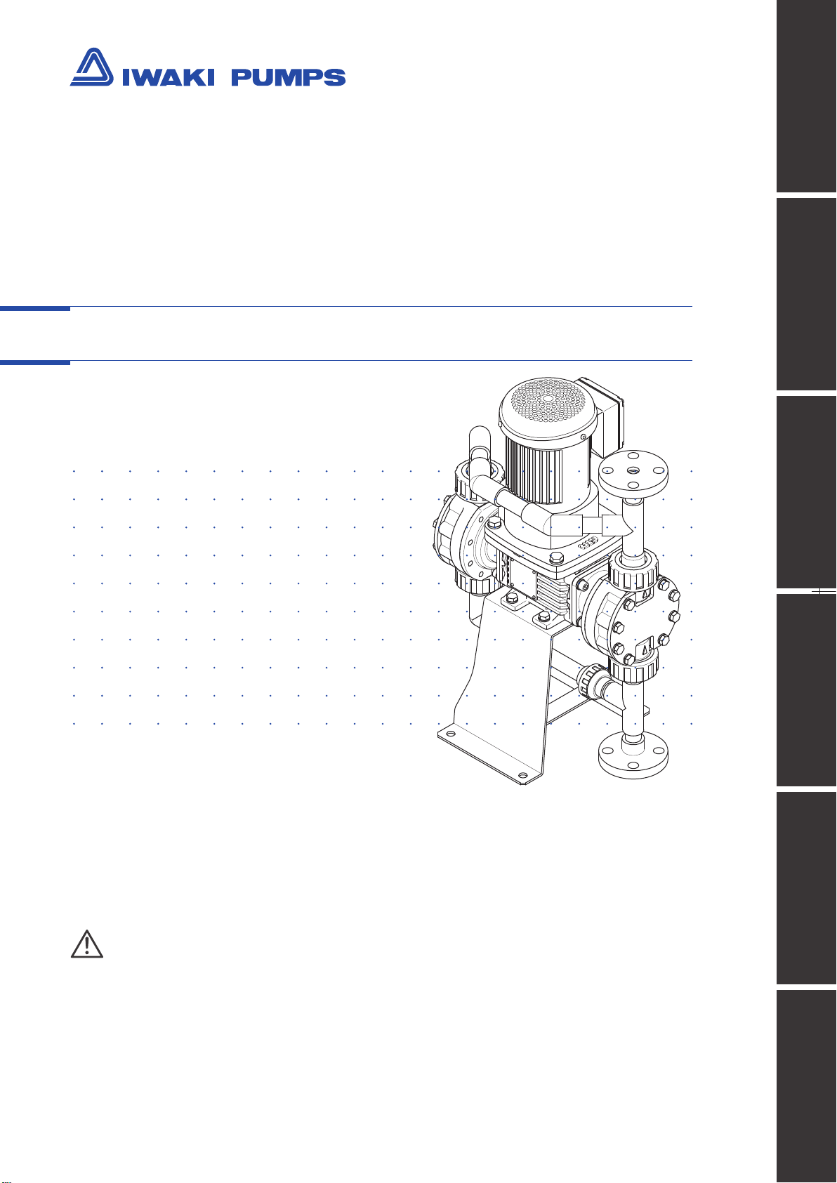
IWAKI Metering Pump
TD series
Safety instructions Overview Installation Operation Maintenance Specication
Instruction manual
Thank you for choosing our product.
Please read through this instruction manual before use.
This instruction manual describes important precautions and instructions for the product. Always keep it on hand for quick reference.
©2011 IWAKI CO., LTD.
Page 2
Order conrmation
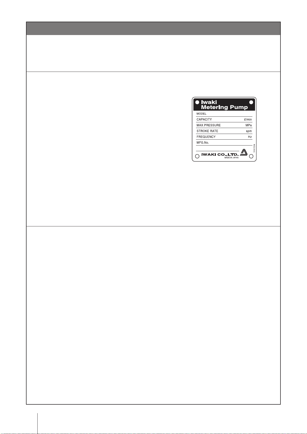
Open the package and check that the product conforms to your order. If any problem or
inconsistency is found, immediately contact your distributor.
a. Check if the delivery is correct.
Check the nameplate to see if the information such as model codes, discharge capacity and discharge
pressure are as ordered.
b. Check if the delivery is damaged or deformed.
Check for transit damage and loose bolts.
Order conrmation
2
Page 3

Contents
Order conrmation ..........................................................................................................................................2
Safety instructions .................................................................... 5
Warnings ........................................................................................................................................................6
Cautions .........................................................................................................................................................8
Precautions for use ....................................................................................................................................10
Overview ...................................................................................11
Introduction ................................................................................................................................................. 11
Pump structure & Operating principle ...................................................................................................... 11
Pump mechanism ....................................................................................................................................12
Flow pulsation reduction mechanism ..................................................................................................12
Part names ...................................................................................................................................................13
Pump ........................................................................................................................................................13
TD .......................................................................................................................................................13
Identication codes ....................................................................................................................................14
Installation ...............................................................................15
Pump mounting ...........................................................................................................................................15
Before installation .....................................................................................................................................15
Pipework ......................................................................................................................................................16
Piping layout .............................................................................................................................................16
Necessary devices ...................................................................................................................................17
Relief valve ..........................................................................................................................................17
Back pressure valve ............................................................................................................................17
Strainer ................................................................................................................................................17
Pressure gauge ...................................................................................................................................17
Pump inlet/outlet connections ..................................................................................................................18
Tube connection ..................................................................................................................................18
Union connection ................................................................................................................................18
Piping precautions ....................................................................................................................................19
Prohibited piping .................................................................................................................................19
Slurry delivery ..........................................................................................................................................20
Wiring ...........................................................................................................................................................21
Inverter-Motor ...........................................................................................................................................21
Inverter-Grid power ..................................................................................................................................21
IPM motor terminal box ............................................................................................................................22
Contents
3
Page 4

Operation ................................................................................. 23
Before operation .........................................................................................................................................23
Operation .....................................................................................................................................................24
Starting procedure ...................................................................................................................................24
Inverter operation .....................................................................................................................................25
Start/Stop of operation ........................................................................................................................25
Flow rate adjustment ...........................................................................................................................25
Before stoppage .......................................................................................................................................26
Resumption after a long period of stoppage ............................................................................................26
Maintenance ............................................................................ 27
Troubleshooting ..........................................................................................................................................27
Inspection ....................................................................................................................................................29
Daily inspection ........................................................................................................................................29
Periodic inspection ...................................................................................................................................29
Maintenance of IPM motor .......................................................................................................................29
Oil replacement (drive unit) ......................................................................................................................30
Replacement procedure ......................................................................................................................31
Wear part replacement ...............................................................................................................................32
Before assembly/disassembly ..................................................................................................................33
Exploded view .............................................................................................................................................34
Pump head ...............................................................................................................................................34
TD-01/-03 VC/V6 ................................................................................................................................34
TD-05/-1 VC/V6/VS ............................................................................................................................36
TD-01/-03 VS ......................................................................................................................................38
TD-2/-4/-6/-8 VC/V6/VS .....................................................................................................................40
TD-01/-03 S6 ......................................................................................................................................42
TD-05/-1 S6 ........................................................................................................................................44
TD-2/-4/-6/-8 S6 .................................................................................................................................46
Specications/Outer dimensions ..............................................................................................................48
Specications ...........................................................................................................................................48
Pump ...................................................................................................................................................48
Inverter ................................................................................................................................................49
Outer dimensions .....................................................................................................................................50
FF type ................................................................................................................................................50
HH type ...............................................................................................................................................51
UU type ...............................................................................................................................................51
Performance curves .................................................................................................................................52
TD-VC/-V6 ...........................................................................................................................................52
TD-S6 ..................................................................................................................................................54
TD-VS .................................................................................................................................................56
Contents
4
Page 5
Safety instructions
Read through this section before use. This section describes important
information for you to prevent personal injury or property damage.
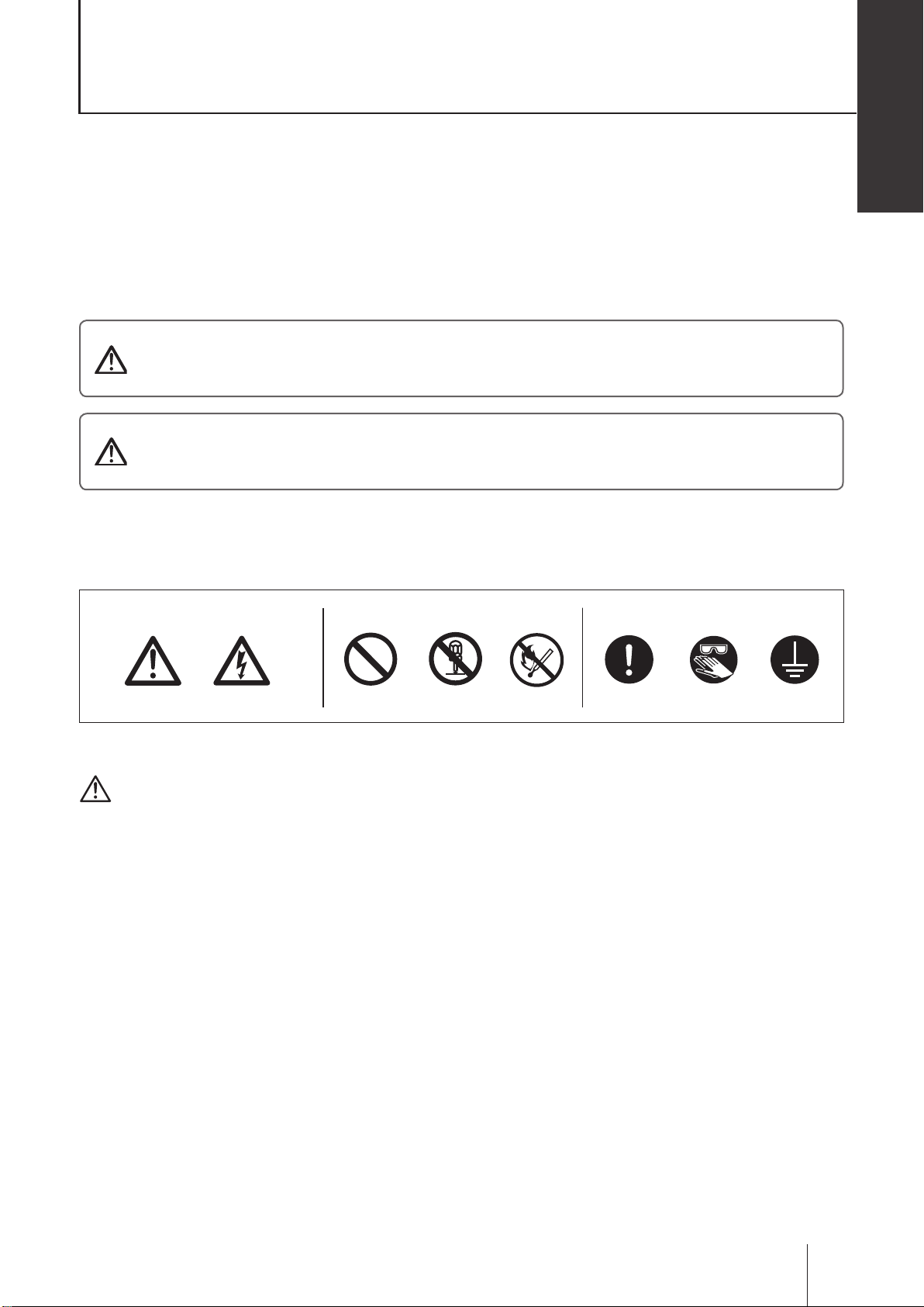
■ Symbols
In this instruction manual, the degree of risk caused by incorrect use is noted with the follow-
ing symbols. Please pay attention to the information associated with the symbols.
Indicates mishandling could lead to a fatal or serious
WARNING
CAUTION
accident.
Indicates mishandling could lead to personal injury or prop-
erty damage.
Safety instructions
A symbol accompanies each precaution, suggesting the use of "Caution", "Prohibited actions"
or specic "Requirements".
Caution marks Prohibition mark Requirement mark
Caution
Electrical
shock
Prohibited
Do not rework
or alter
Fire ban
Requirement
Wear
protection
Grounding
Export Restrictions
Technical information contained in this instruction manual might be treated as controlled tech-
nology in your countries, due to agreements in international regime for export control.
Please be reminded that export license/permission could be required when this manual is
provided, due to export control regulations of your country.
Safety instructions
5
Page 6
Requirement
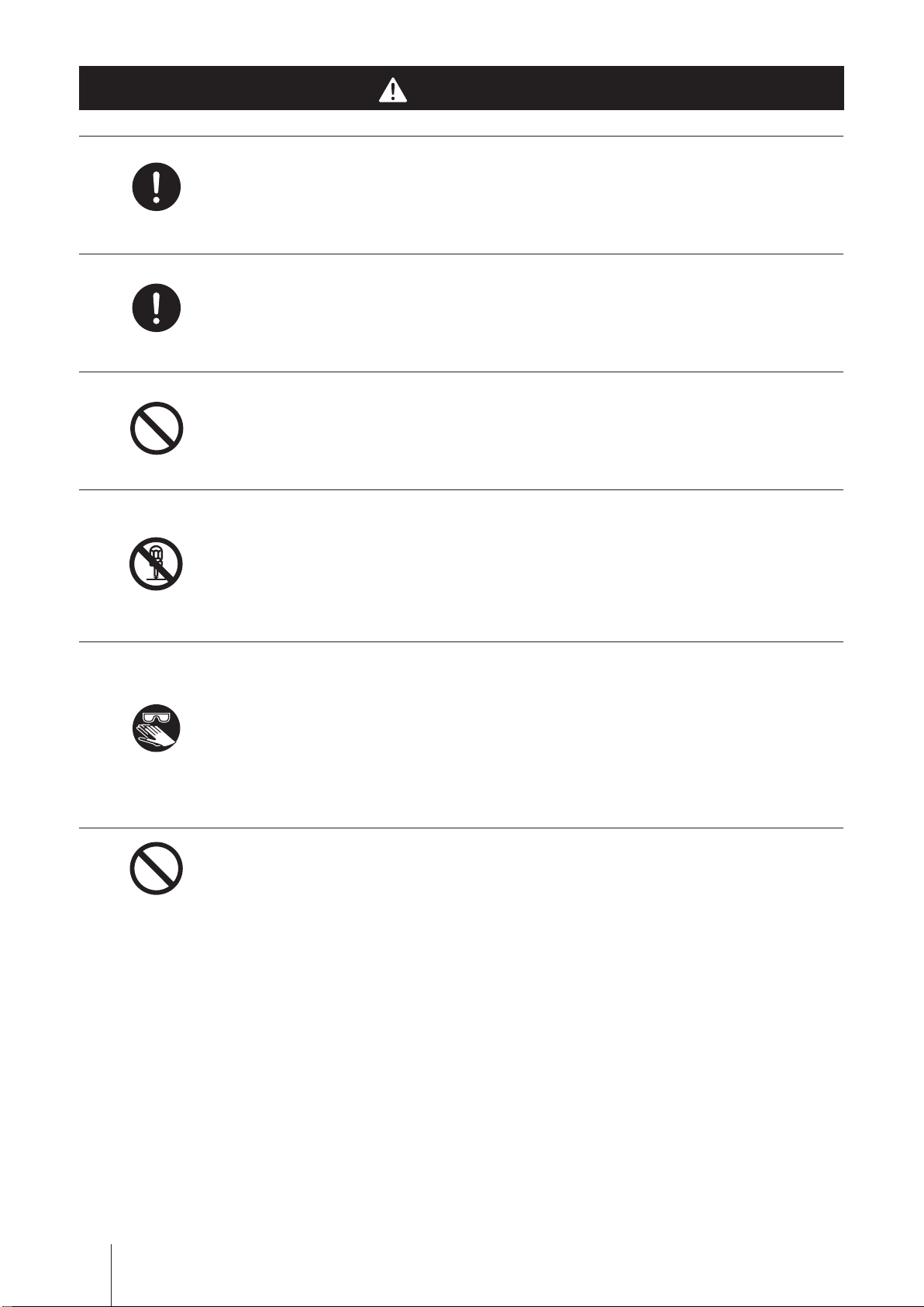
WARNINGS
Turn off power before service
Risk of electrical shock. Be sure to turn off power to stop the pump and
related devices before service is performed.
Stop operation
If you notice any abnormal or dangerous conditions, suspend operation
Requirement
Prohibited
Do not remodel
Wear
protectors
immediately and inspect/solve problems.
Do not use the pump in any condition other than its intended purpose
The use of the pump in any conditions other than those clearly specied
may result in failure or injury. Use this product in specied conditions only.
Do not modify the pump
Alterations to the pump carries a high degree of risk. It is not the manufac-
turer's responsibility for any failure or injury resulting from alterations to the
pump.
Wear protective clothing
Always wear protective clothing such as an eye protection, chemical re-
sistant gloves, a mask and a face shield during disassembly, assembly or
maintenance work. The specic solution will dictate the degree of protec-
Prohibited
tion. Refer to MSDS precautions from the solution supplier.
Stay out from under suspended loads
Risk of personal injury. Keep away from the pump while it is lifted up.
WARNINGS
6
Page 7
WARNINGS
Do not stand on the pump
Do not use the pump as a platform. Injury or damage may result when the
Safety instructions
Prohibited
Caution
Requirement
Prohibited
pump turns over.
Do not get access to the inside of the driven unit during operation
Risk of personal injury. A reciprocating diaphragm/shaft may catch the fin-
ger or hand.
Qualied personnel only
The pump should be handled or operated by qualified personnel with a
full understanding of the pump. Any person not familiar with the product
should not take part in the operation or management of the pump.
Closed-discharge operation is not allowed
Do not close a discharge line during operation. Otherwise, overpressure
will cause liquid leakage or break the pump and piping. Note for the TD
series, a discharge valve is not used for controlling a ow rate.
Requirement
Do not use grid power directory to the pump
Always use an applicable inverter for powering the pump, or fire may
result.
WARNINGS
7
Page 8
Fire ban
CAUTIONS
Use specied power only
Do not apply power other than that specied on the nameplate. Otherwise,
Requirement
Prohibited
Requirement
Caution
failure or re may result. Ensure the pump is properly grounded.
Do not install/store the pump:
• In a ammable/explosive/corrosive atmosphere.
• In a dusty/humid environment.
• Where ambient temperature can exceed 0-40ºC.
• Under mechanical vibrations.
Spill precautions
Ensure protection and containment of solution in the event of plumbing or
pump damage (secondary containment).
Do not touch the pump or pipe with bare hands
Risk of burning. The surface temperature of the pump or pipe rises high
along with liquid temperature in or right after operation.
Electrical
shock
Requirement
Do not bring the pump close to a ammable substance
Keep the pump away from a ammable substance for the prevention of
re. Do not allow a leak of lubricating oil. Observe local rules and regula-
tions for handling of oils.
Install a GFCI (earth leakage breaker)
An electrical failure of the pump may adversely affect other devices on the
same line. Purchase and install an earth leakage breaker separately.
Foreign matter
When foreign matters enter the pump, turn off power immediately to re-
move them. Using the pump with foreign matters may result in failure.
CAUTIONS
8
Page 9
CAUTIONS
Preventative maintenance
Follow instructions in this manual for replacement of wear parts. Do not
Safety instructions
Requirement
Prohibited
Requirement
Prohibited
disassemble the pump beyond the extent of the instructions.
Do not use a damaged pump
Use of a damaged pump could lead to an electric shock or death.
Disposal of a used pump
Dispose of any used or damaged pump in accordance with local rules
and regulations. If necessary, consult a licensed industrial waste disposal
company.
Do not cover the pump with cloth
The motor temperature may build up and a re or an electric/mechanical
failure may result.
Non freezing
Frozen liquid may damage the pump and piping. Drain liquid before leav-
Requirement
Requirement
ing it for a long time or use measures to prevent liquid from freezing in
winter.
Pressure removal
Solution in the discharge line may be under pressure. Release the pres-
sure from the discharge line before disconnecting plumbing or disassem-
bly of the pump to avoid solution spray.
CAUTIONS
9
Page 10
Precautions for use
• Electrical work should be performed by a qualied electrician. Otherwise,
personal injury or property damage may result.
• Shipping inspection with tap water is conducted on every pump. Be sure to
dry off the pump head before operation, or residual water may cause unde-
sirable reaction when having contact with some chemicals.
• Use care handling the pump. Do not drop. An impact may affect pump
performance. Do not use a pump that has been damaged to avoid the risk
of electrical damage or shock.
• The pump is not waterproof. Do not operate the pump while wet with solu-
tion or water, or failure or injury may result. Immediately dry off the pump if
it gets wet.
Caution
Requirement
Caution
Caution
• Do not clean the pump or nameplate with a solvent such as benzine and
thinner. This may discolour the pump or erase printing. Use a dry or a
damp cloth or a neutral detergent.
• Drain liquid before leaving the pump for a long time.
Caution
Requirement
Precautions for use
10
Page 11

Overview
Pump characteristics, features and part names are described in this section.
Introduction
The TD series is the mechanically-driven diaphragm pump. Its pulse-reduction design en-
sures low ow pulsation without the need of an air chamber. A wide selection range of wet
ends allows for delivery of acid, alkaline, viscous liquid, slurry and solvent in various plants or
built-in applications.
Pump structure & Operating principle
Motor rotation is transmitted to an eccentric cam via a reduction gear and then converted to reciprocating
motion. Volumetric change occurs in the pump chamber as the diaphragm moves back and forth, so liquid is
delivered through the outlet with the assistance of the suction and discharge check valves.
Suction process
When the diaphragm moves back, negative pressure in the pump head opens the suction check valve to take
in liquid while closing the discharge check valve.
Overview
Discharge process
When the diaphragm moves forward, positive pressure in the pump head opens the discharge check valve to
deliver liquid while closing the suction check valve.
Motor
Outlet
Check valve
Pump head
Inlet
Diaphragm
Gear unit
Pump shaft
: Liquid flow
: Motor rotation
: Diaphragm reciprocation
: Valve movement
Introduction
11
Page 12
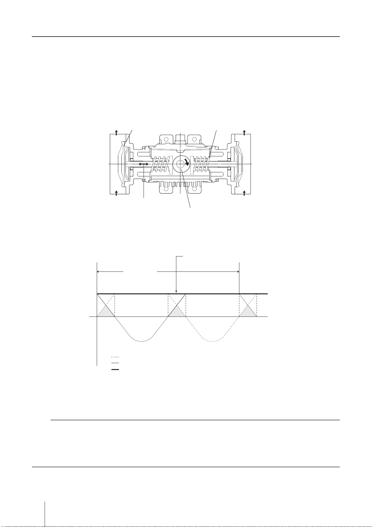
Pump mechanism
0
■ Flow pulsation reduction mechanism
The reduction mechanism consists of the two factors. One is the use of a highly-precise constant-velocity cam,
which makes a trapezoidal waveform of each discharge. The other is the phase shift of two different discharge,
The rear head moves out of phase with the front by 180 degrees to make a constant synthesized waveform.
The ow rate of the TD can change with a motor rotation speed (inverter frequency).
* Note suction pulsation is not reduced.
Constant-velocity cam and Phase shift
Inlet
Discharge/Suction waveform
Discharge process
Pump shaft
One cycle
Front head
SpringOutlet Diaphragm
Constant-velocity cam
Constant synthesized waveform
Rear head
Outlet
Inlet
Suction process
Discharge/Suction volume of the front head
Discharge/Suction volume of the rear head
Total discharge volume consists of both heads
NOTE
The mechanically-driven diaphragm pump including the TD by its nature involves flow pulsation during op-
eration. The reduction mechanism can reduce but can't eliminate the pulsation completely, and the pulsation
becomes greater as a discharge pressure gets higher. This is because the diaphragm transiently depressed
under a high pressure as with every other mechanically-driven diaphragm pumps.
12
Introduction
Page 13
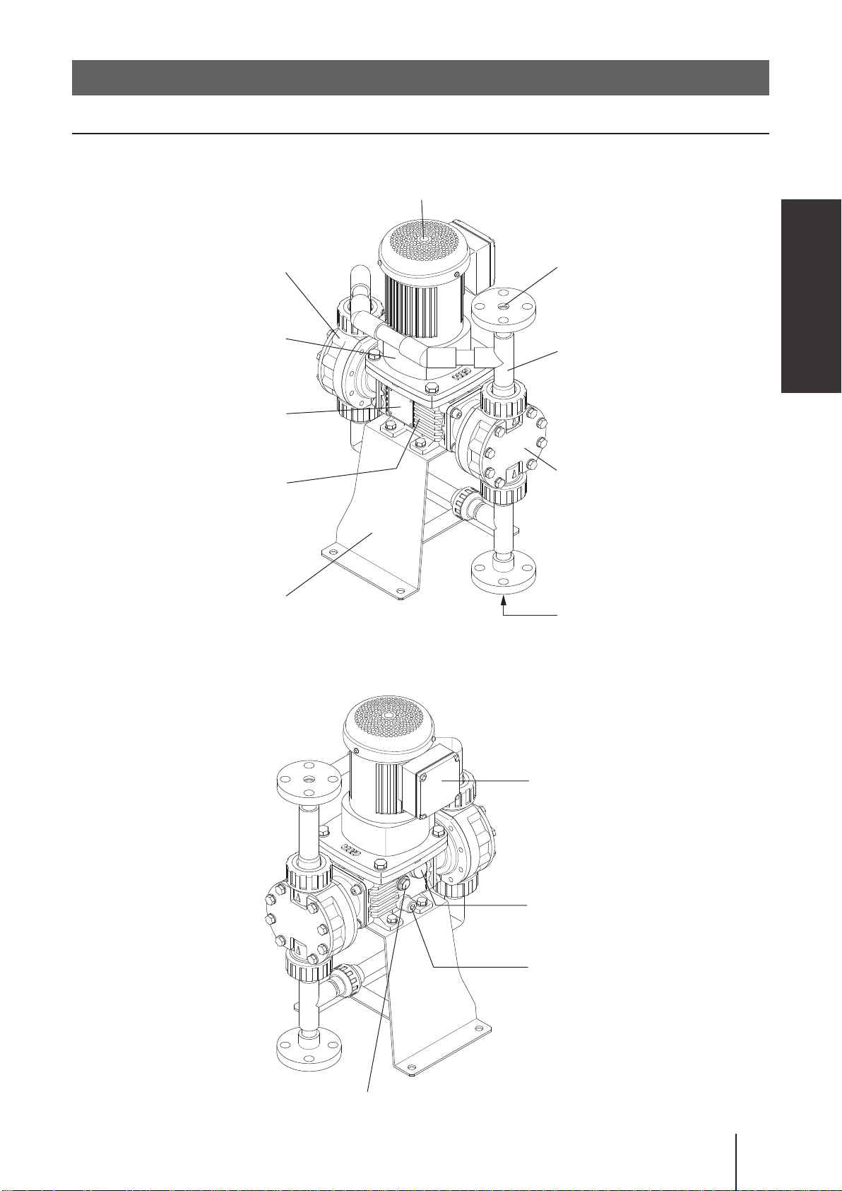
Part names
Pump
■ TD
Rear pump head
Motor
Overview
Outlet
Gear unit
Nameplate
Driven unit
Baseplate
Pipe unit
Front pump head
Inlet
Oil gauge
Terminal box
Oil-filler cap
Oil-drain port
Part names
13
Page 14

Identication codes
Each code represents the following information.
TD - 2 VC FF 1 S - 02 S
a b c d e f g h i
a. Series name
TD
b. Drive unit
M : High-efciency IPM fan motor
No code : High-efciency IPM fanless motor
c. Diaphragm size
01, 03, 05, 1, 2, 4, 6, 8
d. Wet end materials
Code Pump head Valve Valve seat O ring Valve gasket Diaphragm
VC PVC CE
V6 PVC SUS316
VS PVC SUS316 SUS304 EPDM PTFE PTFE+EPDM
S6 SUS316/SCS14 SUS316 SUS316 - PTFE PTFE+EPDM
*DS stands for diaphragm size
FKM: 01-1 (*DS)
PVC: 2-8 (*DS)
EPDM: 01-1 (*DS)
PVC: 2-8 (*DS)
FKM PTFE PTFE+EPDM
EPDM PTFE PTFE+EPDM
Material code
PVC : Polyvinyl chloride SUS316 : Austenitic stainless steel
SUS304 : Austenitic stainless steel SCS14 : Stainless cast steel (SUS316)
CE : Alumina ceramics FKM : Fluorine-contained rubber
EPDM : Ethylene-propylene rubber PTFE : Polytetrauoroethylene
e. Connection type
FF : JIS ange
UU : Union
HH : Tube
* These three connection codes are standard options. Other codes such as FU or UH can be selectable as necessary. In
this case the rst code represents the inlet and the second code the outlet, e.g. FU means JIS ange inlet + union outlet.
*Any union connection is not available for the pumps with 2, 4, 6 and 8 diaphragm sizes and of the S6 type.
*Any tube connection is not available for the pumps with 2, 4, 6 and 8 diaphragm sizes and of the S6 type.
f. Connection direction
1 : Horizontal inlet and outlet
2 : Vertical inlet and outlet
3 : Horizontal inlet and Vertical outlet
4 : Vertical inlet and Horizontal outlet
*The 3rd option is available only for pumps with UU or HH connection type.
g. Special version (pump head)
No code : Standard S : Custom design (e.g. special check valves or pipe I.D.)
h. Motor
0.2 : 0.2kW
i. Special version (drive unit)
No code : Standard S : Custom design (e.g. special motors or baseplates)
14
Identication codes
Page 15

Installation
This section describes the installation of the pump, piping and wiring.
Read through this section before installation is performed.
Points to be observed
Observe the following points when installing the pump:
• Be sure to turn off power to stop the pump and related devices before installation is per-
formed.
• If you notice any abnormal or dangerous conditions, suspend operation immediately and
inspect/solve problems.
• Do not place explosive or ammable material near the pump.
• Do not use a pump that has been damaged to avoid the risk of electrical damage or
shock.
• Use care handling the pump. Do not drop. An impact may affect pump performance.
• Keep the pump as level and as low as possible when it must be lifted up.
• Fumes or vapours can be hazardous with certain solutions. Ensure proper ventilation at
the operation site.
• Observe information on the appropriate drawing and specification sheet.
Pump mounting
Before installation
Check if installation doesn't adversely affect facility, surrounding equipment and the pump. Install the pump according to the following instructions to ensure the optimum performance, safety and service.
• Allow sufcient space around the pump for easy access and maintenance.
• Select a level location, free from vibration, that won't hold liquid. Always use a level gauge.
• Install the pump as close to a supply tank in a ooded suction system.
• Avoid installing the pump:
- In direct sunlight or wind & rain.
- In a dusty/humid place.
- In a corrosive atmosphere.
- In a place where proper ventilation is not maintained.
Installation
Pump mounting
15
Page 16
Pipework
Pipework must be done according to the following instructions to ensure the optimum performance, safety and service.
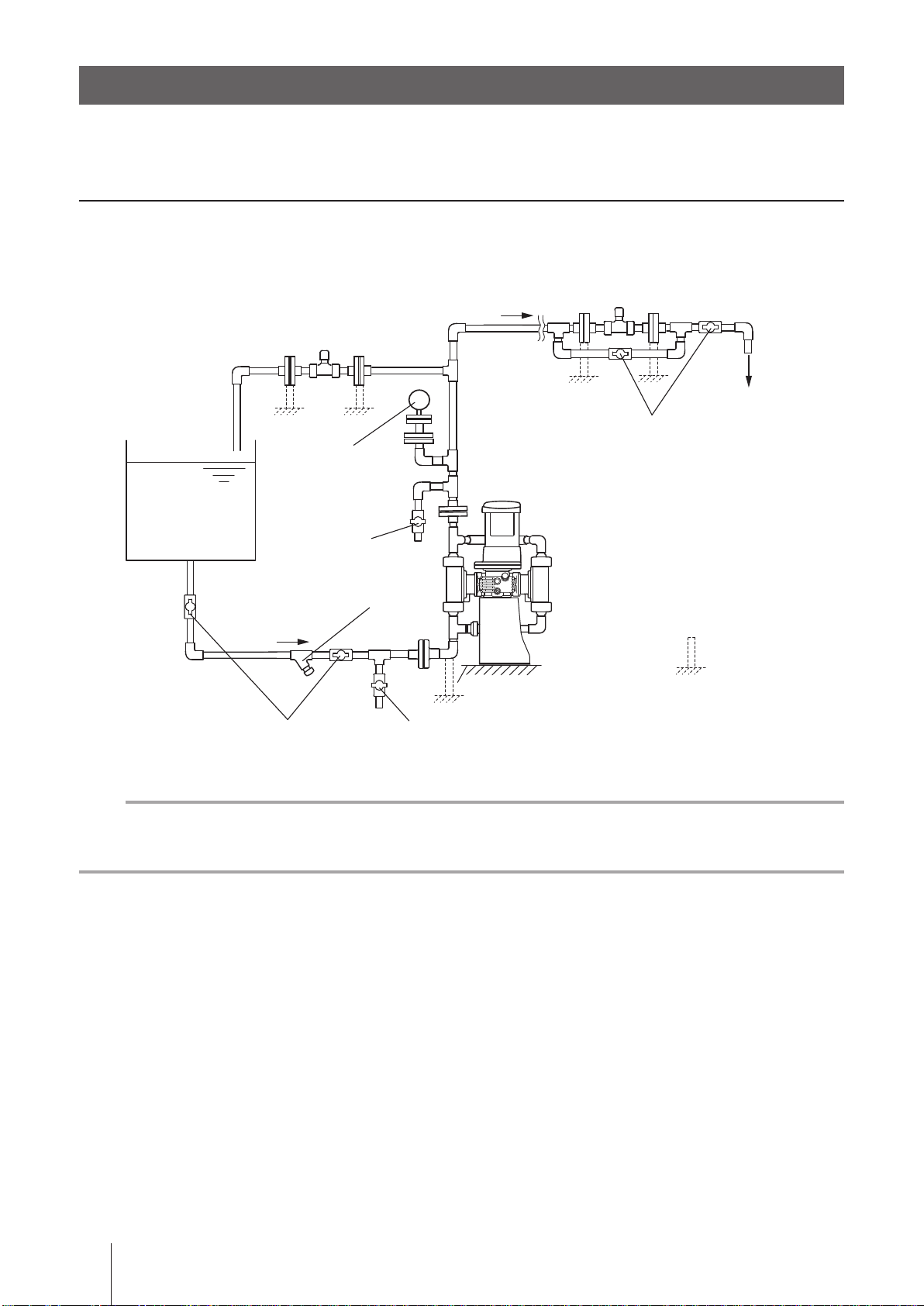
Piping layout
Arrange pump and pipework based on the following piping layout for a long period of operation.
Back pressure valve
Discharge line
Relief valve
(overfeeding prevention)
Injection point
: Pipe support
Flooded suction
Supply tank
Discharge pressure
monitoring gauge
Air vent valve
Y shaped strainer
Suction line
Suction valve
(shut off valve)
P
Maintenance valve
Drain valve
NOTE
• Design an optimal layout to meet NPSHr, especially when planning to deliver slurry.
• If pipework directory weighs on the pump, the pump may be damaged. Be sure to install pipe supports.
16
Pipework
Page 17

Necessary devices
The following devices are needed to the metering pump. Be sure to install, or personal injury or property damage may result.
■ Relief valve
The metering pump by nature keeps working, exceeding the limit pressure of discharge line if it is blocked. This
may damage the pump/piping system and burn out the motor. Install a relief valve close to the pump and x its
set pressure below the maximum allowable pressure of the pump/discharge line.
■ Back pressure valve
Discharge line pressure must be 0.03MPa or higher than suction line pressure. Otherwise, check valve may
not check ow and overfeeding may result. Install a back pressure valve on the discharge line to keep the mini-
mum pressure difference as necessary.
■ Strainer
Provide a 40-mesh strainer at the end of a suction line and clean it periodically. Otherwise, clogging may
result.
Installation
■ Pressure gauge
Install a pressure gauge to monitor the discharge line pressure.
Glossary
Overfeeding is the condition that check valves in the pump head stay open and liquid continues flowing
into discharge line. Always keep the discharge line pressure 0.03MPa or higher than a suction line pres-
sure.
Pipework
17
Page 18
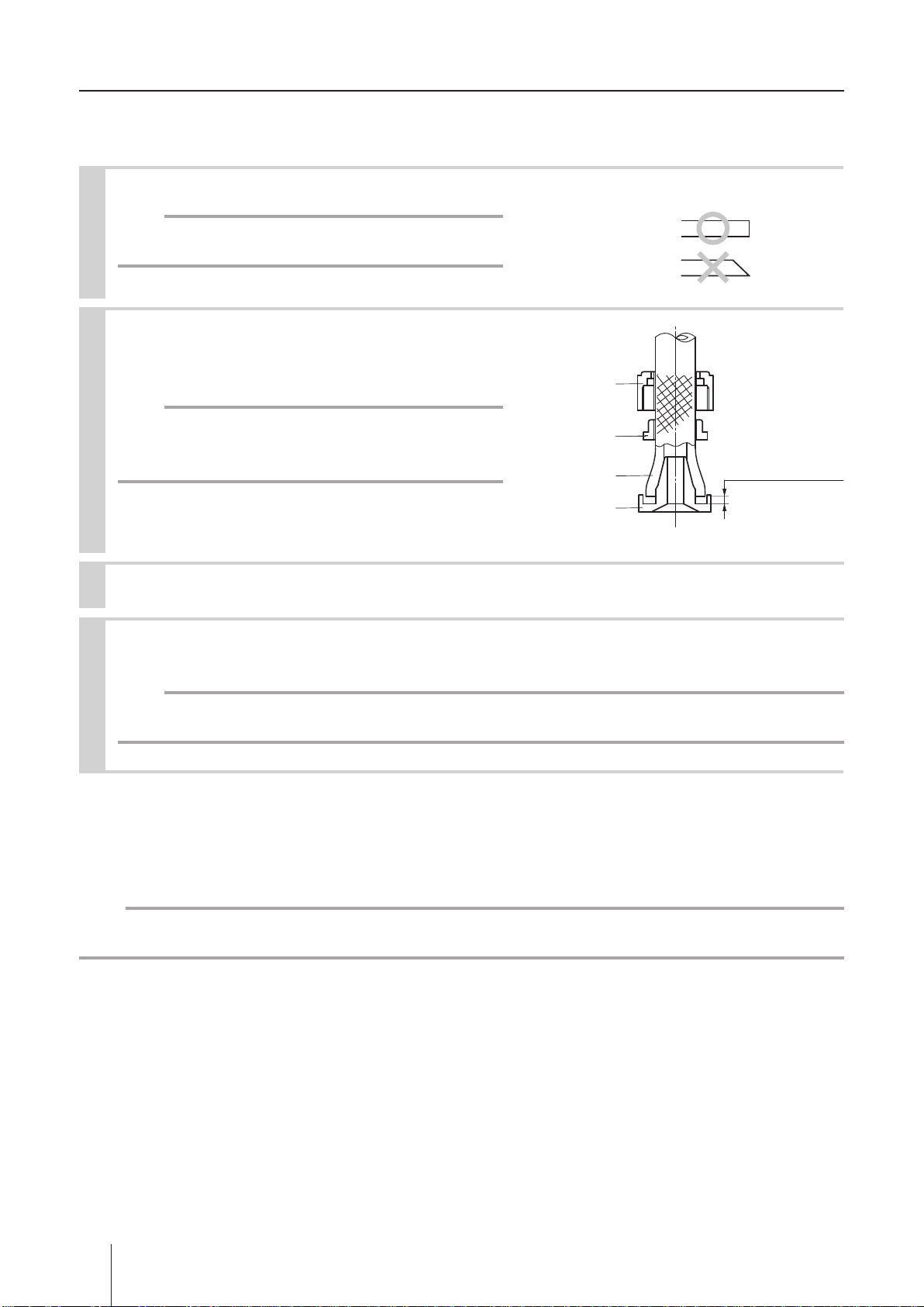
Pump inlet/outlet connections
Arrange the pump inlet and outlet according to a piping system in which the pump is incorporated.
■ Tube connection
Cut the tube ends at.
1
NOTE
Otherwise a leak may result.
Pass a tube into the tting nut and stopper and
2
then slide it down to the tube adapter as far as
it will go.
NOTE
The tube end must come within at least 2mm from the
bottom of the adapter.
Fitting nut
Stopper
Tube
Tube adapter
Tube end (Side view)
Within 2mm
from the bottom
Place an O ring into the inlet/outlet unit (part # 70/71).
3
Secure the tube end (with the tube adapter) on the inlet/outlet unit by hand-tightening the
4
tting nut.
NOTE
The plastic tting nut may be broken if tightened too much.
■ Union connection
Connect the union socket (72) to a plastic ange or joint of your piping system. Use an adhesive to secure the
connection.
NOTE
Do not allow an extra amount of adhesive to enter the pump.
18
Pipework
Page 19

Piping precautions
• Foreign matters such as sand and scale may enter pipework while service is performed. They may cause
fatal damage to the pump. Be sure to blow them out before operation. Also, do not apply adhesive too much
or leave a screw or nut.
• If pipework directory weighs on the pump, the pump may deform. Be sure to install pipe supports.
• Flange connection must be free from any tension or distortion, or a leak or pipe damage may result.
• The suction line I.D. should be equal to or wider than the I.D. of the pump inlet.
• Always keep the inlet of the pump below the liquid level of the supply tank (ooded suction).
• The pump suffers greater pressure loss as the piping length gets longer. Excessive piping resistance may
damage the pump depending on operating conditions such as liquid viscosity, liquid specic gravity and pip-
ing length. Contact us for detail.
■ Prohibited piping
The suction line I.D. is smaller than the
I.D. of the pump inlet. Risk of cavitation.
Suction lift application may adversely affect flow accuracy.
Installation
P
The suction line is too long. Risk of cavitation,
air ingress or greater flow pulsation.
P
P
P
Arched suction line may adversely affect flow accuracy.
P
Pipework
19
Page 20

Slurry delivery
The TD can deliver slurry with some limitations. Contact us for allowable particle size and concentration.
• Branch a drain line from the discharge line.
PP
Drain
• Do not allow any inverted arch line in pipework where slurry can stay.
• Reduce (optimise) the suction and the discharge line I.D. as long as the NPSHr is satised in order to obtain
the maximum possible speed of ow.
• Install a ushing line (tap water) for removing slurry from the pump and piping after delivery.
• Do not use a back pressure valve. The valve may be damaged or clogged by slurry.
• With no use of a back pressure valve, the minimum differential pressure (0.03MPa or higher discharge pres-
sure than suction pressure) may not be satised and overfeeding may occur. In this case extend the dis-
charge line upwards to increase the pressure to the necessary level.
• If the relief valve has opened to release overpressure and been contaminated by slurry, take apart and clean
the inside to remove slurry.
• If an injection point at the end of discharge line is located at a lower position than a tank liquid level, siphon
will take place. In this case extend the rising part of discharge line over the liquid level and then separate the
falling part of it before the tank liquid level.
Tank liquid level
Pipework
20
Flushing line
Extension
P
Set apart the falling part of
discharge line before a tank
liquid level to prevent siphon.
Injection point
Drain
Page 21

Wiring
NFB
Wiring for the inverter and the motor.
Points to be observed
Observe the following points during wiring work:
Do not use grid power directory to the pump. Always use an applicable inverter for pow-
•
ering the pump, or fire may result.
Electrical work should be performed by a qualied electrician. Always observe applica-
•
ble codes or regulations.
Do not perform wiring work while electric power is on. Otherwise, an electrical shock or
•
a short circuit may result. Be sure to turn off the power before wiring work.
Inverter-Motor
Electrically connect the inverter and the motor through the U, V and W lines. See the diagram below for detail.
Wiring diagram
Inverter output terminal
Motor terminal
U/ T1 V/T2 W/T3
↓ ↓ ↓
U V W
Black Gray White
Installation
NOTE
• Connect an electric conduit to the ø21.5mm hole of the motor-terminal box to cover the Inverter-Motor wiring.
• Always check the U, V and W lines are properly connected. Miswiring leads to signicant pulsation in a discharge line.
• Do not extend the U, V and W lines longer than 50m. Do not use a shielded cable for the lines.
Inverter-Grid power
Electrically connect the inverter with a grid power through the R, S and T lines. See manufacturer's manuals
for details of the inverter. Install a NFB for easy maintenance.
R
S
T
GND
R
S
T
INV
U/T1
V/T2
W/T3
U
Black
V
Gray
W
White
Green/Yellow
Motor
NFB: Non-Fuse Breaker
INV: Inverter
Wiring
21
Page 22

IPM motor terminal box
53
80
Use an electric conduit for the Inverter-Motor wiring. See the dimension below for detail. A conduit connection
hole of I.D. 21.5mm is made on a 4mm thick terminal box.
Aluminium terminal box
80
4
ø21.5
Motor
Unit: mm
22
Wiring
Page 23

Operation
This section describes pump operation and programming. Run the pump
after pipework and wiring are completed.
Before operation
Always check the following items before the rst-time operation or resuming operation after a
long period of stoppage.
Points to be observed
Observe the following points during operation:
• The pump should be handled or operated by qualified personnel with a full understand-
ing of the pump. Any person not familiar with the product should not take part in the
operation or maintenance of the pump.
•
Risk of burning. The surface temperature of the pump or motor rises up to 80ºC in or
right after operation.
•
Do not close a discharge line during operation. Otherwise, liquid leakage or pump head/
motor/piping breakage may result due to overpressure.
•
Do not close a suction line during operation. Otherwise, internal parts are excessively
worn by friction heat and fatal pump damage results.
• Risk of electrical shock. Be sure to turn off power to stop the pump and related devices
before service is performed.
• Check for transit damage, loose bolts and an oil leak.
• Check the motor rated voltage corresponds to the power voltage supplied to the inverter. See motor name-
plate.
• Electrical wiring must be correct. See the "Wiring" section on page 21 and inverter manufacturer's manual.
• Check a liquid level in the supply tank.
• Check if the discharge and suction lines are laid correctly.
• Check the oil gauge on the driven unit. An oil level should be at the middle of the gauge (marked in red).
Red mark
Operation
Before operation
23
Page 24

Operation
Read this section before operation.
Starting procedure
Start the pump by the following procedure.
Open the suction and discharge valves.
1
Turn on the inverter power.
2
Push the RUN key to start the pump.
3
See page 25 for detail.
NOTE
Set the frequency dial to about 10Hz at the start. Increase the drive frequency as necessary in later steps.
Check the rotational direction of the motor.
4
Clockwise seen from the motor end (positive rotation) is the correct direction.
NOTE
For the pumps with a fanless motor, check output from the pump. Signicant output pulsation may be a
sign of reverse motor rotation. Correct motor wiring as necessary.
Expel air from the pump head.
5
Open an air vent line to expel air while taking in liquid into the pump head. Close the line after the pump
head is lled with liquid.
Check the pump operation for abnormality.
6
In cold climates, an electric current to the motor can double at the start of operation. This overcurrent re-
sults when gear-oil temperature is too low. Run the pump with no discharge pressure until the oil warms
up.
Turn the frequency dial to a desired position.
7
Increase a ow to a specied rate. See page 25 for detail.
Use a calibration cylinder to measure discharge capacity.
8
Repeat measurement. The pump and system are ok when the measured discharge capacity does not
change.
NOTE
Observe the above instructions to keep the optimal operating conditions. If you notice any abnormal or dangerous
conditions, suspend operation immediately and inspect/solve problems. See page 27 "Troubleshooting" or contact us.
Operation
24
Page 25

Inverter operation
See below for the basic operation of the VF-nC3M transistor inverter with default setting. See manufacturer's
manual for other programming including external frequency control.
Frequency display
RUN key
■ Start/Stop of operation
Use the RUN key to start and the STOP key to stop the motor.
STOP key
Frequency dial
Operation
■ Flow rate adjustment
This pump does not have a stroke length knob that general metering pumps have for adjusting a ow rate. The
TD changes a ow rate with the inverter, controlling a motor speed.
NOTE
Observe the allowable control frequency range at each model, or the IPM motor may break. Note that the
following data is based on operation at the maximum discharge pressure (see page 48).
TD-01/-03/-05/-1/-2/-4: 6-60Hz
TD-6/-8: 10-60Hz
Turn the frequency dial clockwise to increase and anticlockwise to decrease Hz and a
1
ow rate.
Operation Drive frequency Details
Power is turned ON
The dial is turned
to 60Hz
Power is turned OFF
0.0Hz
A ow rate is changed to 60.0Hz.
The drive frequency is stored after the inverter is
turned off.
Operation
25
Page 26

Before stoppage
• After everyday operation, release the liquid and pressure from the pump and pipework and turn off power.
• Before a long period of stoppage, flush the inside of the pump and pipework with clean water or cleaning liq-
uid. Completely drain and depressurize them afterwards.
• Frozen liquid may damage the pump and piping. Remove liquid completely in winter.
• Band heaters can be used to keep the pump and piping warm when suspending operation just for a short
period of time in winter.
Resumption after a long period of stoppage
When operation is resumed after a long period of stoppage (one week later), do not run the pump without com-
missioning. Always check a tank liquid level and run the pump according to the starting procedure on page 24.
26
Operation
Page 27

Maintenance
This section describes troubleshooting, maintenance, wear part replace-
ment, exploded views and specications.
Points to be observed
Observe the following points during maintenance work:
• Follow instructions in this manual for replacement of wear parts. Do not disassemble the
pump beyond the extent of the instructions.
• Always wear protective clothing such as an eye protection, chemical resistant gloves, a
mask and a face shield during disassembly, assembly or maintenance work.
• Risk of electrical shock. Be sure to turn off power to stop the pump and related devices
before/during service is performed. See below.
Risk of burning. Do not touch the pump or pipe with bare hands. The surface temperature
•
of the pump or pipe rises high along with liquid temperature in or right after operation.
Troubleshooting
First check the following points. If the following measures do not help remove problems, contact your nearest distributor.
States Possible causes Solutions
Motor does not
starts to run.
Flow is too low.
Flow is too high.
Flow uctuates.
Grid power is directly connected to the motor.
Disconnection
Power fuse has blown. Inspect/solve the root cause of the blowout.
Power voltage reduction
Overpressure (discharge line) Check a discharge line or check valves.
Out of frequency range.
Inverter is not working. Repair the inverter. Replace as necessary.
NPSHr is not satisfied.
A check valve and valve seat have been worn.
Foreign matters in the check valve Take apart and clean the valve.
Clogged suction line or strainer Take apart and clean them.
Air ingress from the suction line.
Different liquid is used.
A relief valve is open. Check/reset the set pressure.
Damaged diaphragm Replace with new one.
Damaged gaskets or O rings Replace with new ones.
Minimal differential pressure of 0.03MPa is
not kept and overfeeding results.
Different liquid is used.
NPSHr is not satisfied.
A check valve and valve seat have been worn.
Use an inverter. Replace motor if necessary.
Replace/reconnect motor wires as necessary.
Inspect/solve the root cause of the reduction.
Observe the allowable frequency. See page 25.
Review the pump and piping system to meet
the NPSHr.
Replace with new ones.
Check for loose connections and retighten
as necessary.
Check liquid characteristics and pump specification.
Keep the minimal differential pressure. Use
a back pressure valve as necessary.
Check liquid characteristics and pump specification.
Review the pump and piping system to meet
the NPSHr.
Replace with new ones.
Maintenance
Troubleshooting
27
Page 28

States Possible causes Solutions
gaseous liquid Take measures to reduce gas.
No discharge
Great pulsation
Discharge pres-
sure is too low.
Liquid leaks.
Air ingress
from:
No discharge
from:
A leak from: a damaged diaphragm Replace with new one.
Reverse motor rotation. Use an inverter or correct wiring.
A check valve and valve seat have been worn.
Foreign matters in the check valve Take apart and clean the valve.
Suction line vibration is too big. Support the suction lines.
A check valve and valve seat have been worn.
Foreign matters in the check valve Take apart and clean the valve.
Pressure gauge has failed. Replace with new one.
Clogging in a pressure gauge Remove clogging.
A relief valve is open. Check/reset the set pressure.
Damaged diaphragm Replace with new one.
Overpressure (discharge line)
Damaged diaphragm Replace with new one.
Damaged gaskets or O rings Replace with new ones.
Misarranged valve assembly Rebuild it in correct order.
Loose connection of the inlet and outlet Tighten them as necessary.
Loose pump-head-fixing-bolts Tighten them as necessary.
Motor failure Replace with new one.
a suction line (imperfect
joint or sealing)
an empty tank
Clogged suction line or strainer
Foreign matters in a check valve
A damaged check valve
and valve seat
Check for an imperfect joint/sealing and
retighten as necessary.
Rell the supply tank. Degassing is required
before resuming operation.
Take apart and clean them.
Take apart and clean the valve.
Replace with new ones.
Replace with new ones.
Replace with new ones.
Inspect/solve the root cause of overpressure.
NPSHr is not satisfied.
A noise level is too
high.
Oil leaks. Damaged gaskets or O rings Replace with new ones.
No suction
Motor temperature
is too high (80ºC
or more).
Damaged driven unit Repair or replace with new one.
Overpressure (discharge line) Inspect/solve the root cause of overpressure.
Oil level, grade or quality is wrong. Check if it is proper. Replace as necessary.
A check valve and valve seat have been worn.
Foreign matters in the check valve Take apart and clean the valve.
Clogged suction line or strainer Take apart and clean them.
Air ingress from a suction line.
Damaged diaphragm Replace with new one.
Damaged gaskets or O rings Replace with new ones.
Entrained air in the pump head. Perform degassing.
Misarranged valve assembly Rebuild it in correct order.
Overpressure (discharge line) Inspect/solve the root cause of overpressure.
Target frequency is too high or low. Reset the dial to a proper position.
Review the pump and piping system to
meet the NPSHr.
Replace with new ones.
Check for loose connections and retighten
as necessary.
Troubleshooting
28
Page 29

Inspection
Perform daily and periodic inspection to keep pump performance and safety.
Daily inspection
Check the following points. Upon sensing abnormality, stop operation immediately and remove problems according to "Troubleshooting".
When wear parts come to the life limit, replace them with new ones. Contact your distributor for detail.
No. Inspection items Points to be checked
1 Noise and vibration
Air ingress from pump head joints
2
and a suction line
3 Pressure gauge/Flow meter/Ammeter
4 Oil gauge on the driven unit • If an oil level is proper and oil is not leaked or deteriorated.
5 Spare pump condition
• If abnormal noise or vibration occurs. They are signs of abnor-
mal operation.
• If leakage occurs.
• If pump head bolts or nuts are loose. Tighten with a torque
wrench as necessary.
• If the rated discharge pressure, flow rate and a motor load current on the spec labels are observed. If not, remove problems.
• If it is usable. Run it from time to time to keep it ready for opera-
tion at any time when needed.
Periodic inspection
Check wear parts such as valve set (a check valve, valve guide, valve seat and valva gasket), diaphragm and
tubing for heavy damage or wear at least every 6 months.
Part names Points to be checked Measures
Check valve, valve guide,
valve seat, valve gasket,
O ring
If they are damaged or worn.
Replace as soon as possible if pump performance has reduced. Note their lives change with
operating conditions such as liquid characteristics.
Replace as soon as possible if pump perform-
Diaphragm If it is damaged or worn.
If it is hardened or discoloured
by ultraviolet-ray or chemical
Tubing
liquid.
If it is damaged by high pressure.
ance has reduced. Note its life changes with operating conditions such as liquid characteristics.
Replace as soon as possible if pump performance has reduced. Note its life changes with operating conditions such as liquid characteristics.
Maintenance of IPM motor
An IPM gear motor used in the TD series pump is the combination of a motor and a reduction gear unit, and
the NLGI #0 extreme pressure lithium base grease is used in the gear unit. This long life grease can be used
up to 10,000 hours of operating time or 3-5 years of useful life, but then needs replaced after either period has
passed. Note replacement of the grease must be conducted by a skilled engineer. Contact us or your distributor.
Maintenance
Inspection
29
Page 30

NOTE
• Tighten the pump head bolts (parts# 20) when a leak is found from the pumphead-bracket seal. See the
exploded view pages for the rated tightening torque at each pump model. If it can't stop a leak, replace the
diaphragm.
• A leak from the vent hole is the sign of diaphragm rupture. Stop the pump immediately and replace the dia-
phragm.
Pumphead-Bracket seal
Pump head
Pump head bolt
Bracket
Vent hole
Oil replacement (drive unit)
Replace the lubricating oil in the drive unit every 4000 hours operation or 1 year after delivery, whichever
comes first.
• When the rst time the pump is used, replace the oil after 500 hours of running-in period to remove initial
abrasion powder. Or abnormal wear may be caused.
• The specied oil volume is about 220mL.
NOTE
Always use the oil brand below. Otherwise, pump damage or in the worst case fair may result.
Specied oil brand
Oil company Brand name
SUMICO LUBRICANT CO., LTD. Molyoil F320
30
Inspection
Page 31

■ Replacement procedure
Prepare a container to receive used oil in advance.
Remove the oil cap.
1
Remove the drain plug.
2
Use a container to collect used oil.
Oil cap
Drain plug
Replace the drain plug after the drive unit is emptied.
3
Remove old seal tape from the drain-plug threads and apply new one before retting the plug.
Rell gear oil.
4
The specied oil volume is about 220ml. Always check an oil level comes to the middle of the oil gauge,
or the driven unit may fail to operate properly.
Maintenance
Red mark
Inspection
31
Page 32

Wear part replacement
To run the pump for a long period, wear parts need to be replaced periodically.
Contact your distributor with the following information for wear part replacement.
1. Part names and part number (see the "Exploded view" section.)
2. Pump model identification code and manufacturing number (see pump nameplate.)
3. Drawing number if you have our approval drawing
Precautions
• Solution in the discharge line may be under pressure. Release the pressure from the
discharge line before disconnecting plumbing or disassembly of the pump to avoid solution spray.
• When dismantling the pump, pay attention to the residual liquid in the pump head.
• Always wear protective clothing such as an eye protection, chemical resistant gloves, a
mask and a face shield during disassembly, assembly or maintenance work.
• Follow instructions in this manual for replacement of wear parts. Do not disassemble the
pump beyond the extent of the instructions.
• Risk of electrical shock. Be sure to turn off power to stop the pump and related devices
before service is performed.
32
Wear part replacement
Page 33

Before assembly/disassembly
• Inch the motor or rotate the motor fan by hand to extend the pump shaft to the maximum length when removing the diaphragm.
• Inch the motor or rotate the motor fan by hand to contract the pump shaft to the minimum length when replacing the pump head to the bracket.
• When a new diaphragm is mounted, clean the diaphragm-side retainer surface and apply the grease; Dow
Corning Toray MOLYKOTE® HP-500. Always apply a screw burning protective agent to the diaphragm shaft.
• Observe the mounting direction of the valve assembly. If the outlet valve assembly is mounted upside down,
the pump falls into closed-discharge operation and excessive pressure may damage the pump or cause per-
sonal injury when it bursts.
• Always fasten the pump head to the specied tightening torque (see the exploded view pages) in diagonal
order. Repeat the procedure once again to make sure the possibility of a leak is eliminated.
31
24
1
6
4 2
3
5
1
8
4
6
5
3
7
2
Maintenance
Wear part replacement
33
Page 34

Exploded view
Pump head
■ TD-01/-03 VC/V6
Tube : HH3
Union : UU3
73
72
76*
Front head
Observe the
mounting direction.
Observe the
mounting direction.
85
84
83
76*
CAUTION
20
CAUTION
Flange : FF1
FF4
77
76*
71
10*
9
5*
3*
2*
4*
7*
22
21
Flange : FF2
78
76*
FF3
Valve set
216*
31
30*
1
7*
5*
3*
Valve set
2*
4*
9
10*
Rear head
Rotate anticlockwise
to remove
diaphragm.
Diaphragm
Pump shaft
Retainer
Apply the specied
grease onto the surface. See page 33 for
detail.
70
76*
72
73
76*
70
Union : UU3
78
Flange : FF1
FF3
85
Tube : HH3
* The parts denoted by an asterisk are wear parts and need replaced periodically (every time the service life has passed).
See the next page for the estimated life of each part based on operation with clean water at room temperature.
*The front and rear pump heads consist of the same component parts and assembly sequence.
Exploded view
34
84
83
76*
Flange : FF2
FF4
CAUTION
Take care not to drop the valve set or not to get
wet with residual chemicals in the pump head
when removing the inlet pipe unit (70).
Inch the motor or rotate the motor
fan by hand to extend the pump
shaft to the maximum length when
mounting the diaphragm. Fasten the diaphragm into the shaft
through the retainer until it bottoms
out and will not turn further.
Page 35

Parts list
No. Part names # of parts Materials Estimated life
1 Pump head 1 PVC 2* Valve 2
3* Valve guide 2 PVC 8000hrs or 1 YR
4* Valve seat 2
5* Valve gasket 2 PTFE 8000hrs or 1 YR
7* O ring 2
9 Fitting 2 PVC -
10* O ring 2
20 Hexagon bolt 4 Stainless steel -
21 Spring washer 4 Stainless steel -
22 Plain washer 4 Stainless steel -
30* Diaphragm 1 PTFE+EPDM 4000hrs or 6 months
31 Retainer 1 SUS304 70 Inlet pipe unit 1 PVC 71 Outlet pipe unit 1 PVC 72 Union socket 2 PVC 73 Nut 2 PVC -
2: FF1/FF3/
76* O ring
77 Flange elbow unit 1 PVC -
78 Flange unit
83 Tube adapter 2 PVC -
84 Stopper 2 SS400 85 Fitting nut 2 CFRPVDF -
216* Oil seal 1 NBR 8000hrs or 1 YR
*The parts with an estimated life are wear parts and need to be replaced periodically.
* The listed number of parts is required to consist of one single pump head except for parts # 70 and 71.
HH3/UU3
1: FF2/FF4
1: FF1/FF2
2: FF3
VC V6
Alumina ceramics SUS316
VC V6
PVC PVC
VC V6
FKM EPDM
VC V6
FKM EPDM
VC V6
FKM EPDM
PVC -
8000hrs or 1 YR
8000hrs or 1 YR
8000hrs or 1 YR
8000hrs or 1 YR
8000hrs or 1 YR
NOTE
Retighten the bolts/parts evenly to the following torque.
Tightening torque
Part No. Torque
#9 5 N•m
#20 2.9 N•m
Exploded view
Maintenance
35
Page 36

■ TD-05/-1 VC/V6/VS
Flange : FF1
77
Tube : HH3
85
Union : UU3
73
72
76*
Front head
84
83
76*
Flange : FF2
FF3
78
FF4
76*
76*
71
CAUTION
Observe the mounting direction.
CAUTION
Observe the mounting direction.
73
Union : UU3
Flange : FF1
72
76*
FF3
10*
9
5*
3*
2*
4*
7*
22
21
20
76*
78
85
Tube : HH3
84
Valve set
1
7*
5*
3*
2*
4*
9
10*
76*
83
Flange : FF2
214*
218
31
30*
Valve set
70
217*
FF4
Rear head
Rotate anticlockwise
to remove diaphragm.
Pump shaft
Retainer
Apply the specied
Diaphragm
grease onto the
surface. See page
33 for detail.
70
Inch the motor or rotate the motor fan by hand
to extend the pump shaft to the maximum length
when mounting the diaphragm. Fasten the diaphragm into the shaft through the retainer until it
bottoms out and will not turn further.
CAUTION
Take care not to drop the valve set or not to get
wet with residual chemicals in the pump head
when removing the inlet pipe unit (70).
* The parts denoted by an asterisk are wear parts and need replaced periodically (every time the service life has passed).
See the next page for the estimated life of each part based on operation with clean water at room temperature.
*The front and rear pump heads consist of the same component parts and assembly sequence.
36
Exploded view
Page 37

Parts list
No. Part names # of parts Materials Estimated life
1 Pump head 1 PVC 2* Valve 2
3* Valve guide 2 PVC 8000hrs or 1 YR
4* Valve seat 2
5* Valve gasket 2 PTFE 8000hrs or 1 YR
7* O ring 2
9 Fitting 2 PVC -
10* O ring 2
20 Hexagon bolt 6 Stainless steel -
21 Spring washer 6 Stainless steel -
22 Plain washer 6 Stainless steel -
30* Diaphragm 1 PTFE+EPDM 4000hrs or 6 months
31 Retainer 1 SUS304 70 Inlet pipe unit 1 PVC 71 Outlet pipe unit 1 PVC 72 Union socket 2 PVC 73 Nut 2 PVC -
2: FF1/FF3/
76* O ring
77 Flange elbow unit 1 PVC -
78 Flange unit
83 Tube adapter 2 PVC -
84 Stopper 2 SS400 85 Fitting nut 2 CFRPVDF -
214* Oil seal assy 1 - 8000hrs or 1 YR
217* Oil seal gasket 1 Nonasbestos
218 Hex socket head bolt 4 Steel -
*The parts with an estimated life are wear parts and need to be replaced periodically.
* The listed number of parts is required to consist of one single pump head except for parts # 70 and 71.
NOTE
Retighten the bolts/parts evenly to the following torque.
Tightening torque
Part No. Torque
#9 9 N•m
#20 2.9 N•m
HH3/UU3
1: FF2/FF4
1: FF1/FF2
2: FF3
Alumina ceramics SUS316 SUS316
VC V6 VS
VC V6 VS
FKM EPDM SUS304
VC V6 VS
FKM EPDM EPDM
VC V6 VS
FKM EPDM EPDM
VC V6 VS
FKM EPDM EPDM
PVC -
8000hrs or 1 YR
8000hrs or 1 YR
8000hrs or 1 YR
8000hrs or 1 YR
8000hrs or 1 YR
Every time the oil seal
assy is dismantled.
Maintenance
Removal of the Oil seal assy
Screw in the attached two M4 hex sock head
bolts as below to remove the oil seal assy.
M4×25 hex sock head bolt
Oil seal assy
Exploded view
37
Page 38

■ TD-01/-03 VS
Tube : HH3
85
Union : UU3
73
72
76*
Front head
84
83
76*
Flange : FF1
FF4
77
76*
71
10*
Flange : FF2
78
76*
FF3
CAUTION
Observe the mounting direction.
CAUTION
Observe the mounting direction.
72
73
Union : UU3
Flange : FF1
20
76*
FF3
22
21
78
Tube : HH3
9
3*
2*
4*
5*
7*
76*
85
Valve set
7*
3*
2*
4*
5*
9
10*
83
84
216*
31
30*
1
Valve set
76*
Flange : FF2
70
FF4
Rear head
Rotate anticlockwise
to remove
diaphragm.
Pump shaft
Diaphragm
Retainer
Apply the specied
grease onto the surface. See page 33 for
detail.
Inch the motor or rotate the motor
fan by hand to extend the pump
shaft to the maximum length when
mounting the diaphragm. Fas-
70
ten the diaphragm into the shaft
through the retainer until it bottoms
out and will not turn further.
CAUTION
Take care not to drop the valve set or not to get
wet with residual chemicals in the pump head
when removing the inlet pipe unit (70).
* The parts denoted by an asterisk are wear parts and need replaced periodically (every time the service life has passed).
See the next page for the estimated life of each part based on operation with clean water at room temperature.
*The front and rear pump heads consist of the same component parts and assembly sequence.
38
Exploded view
Page 39

Parts list
No. Part names # of parts Materials Estimated life
1 Pump head 1 PVC 2* Valve 2 SUS316 8000hrs or 1 YR
3* Valve guide 2 PVC 8000hrs or 1 YR
4* Valve seat 2 SUS304 8000hrs or 1 YR
5* Valve gasket 2 PTFE 8000hrs or 1 YR
7* O ring 2 EPDM 8000hrs or 1 YR
9 Fitting 2 PVC -
10* O ring 2 EPDM 8000hrs or 1 YR
20 Hexagon bolt 4 Stainless steel -
21 Spring washer 4 Stainless steel -
22 Plain washer 4 Stainless steel -
30* Diaphragm 1 PTFE+EPDM 4000hrs or 6 months
31 Retainer 1 SUS304 70 Inlet pipe unit 1 PVC 71 Outlet pipe unit 1 PVC 72 Union socket 2 PVC 73 Nut 2 PVC -
2: FF1/FF3/
76* O ring
77 Flange elbow unit 1 PVC -
78 Flange unit
83 Tube adapter 2 PVC -
84 Stopper 2 SS400 85 Fitting nut 2 CFRPVDF -
216* Oil seal 1 NBR 8000hrs or 1 YR
*The parts with an estimated life are wear parts and need to be replaced periodically.
* The listed number of parts is required to consist of one single pump head except for parts # 70 and 71.
HH3/UU3
1: FF2/FF4
1: FF1/FF2
2: FF3
EPDM 8000hrs or 1 YR
PVC -
NOTE
Retighten the bolts/parts evenly to the following torque.
Tightening torque
Part No. Torque
#9 5 N•m
#20 2.9 N•m
Maintenance
Exploded view
39
Page 40

■ TD-2/-4/-6/-8 VC/V6/VS
71
Front head
7*
Rear head
CAUTION
Observe the mounting direction.
29
20
CAUTION
Observe the mounting direction.
70
3*
2*
4*
5*
5*
3*
2*
4*
7*
218
217*
214*
31
30*
1
Rotate anticlockwise
to remove diaphragm.
74*
Pump shaft
Retainer
Apply the specied
Diaphragm
grease onto the surface. See page 33 for
CAUTION
Take care not to drop the valve set or not to get
wet with residual chemicals in the pump head
when removing the inlet pipe unit (70).
Inch the motor or rotate the motor fan by hand
to extend the pump shaft to the maximum length
when mounting the diaphragm. Fasten the dia-
detail.
phragm into the shaft through the retainer until it
bottoms out and will not turn further.
* The parts denoted by an asterisk are wear parts and need replaced periodically (every time the service life has passed).
See the next page for the estimated life of each part based on operation with clean water at room temperature.
*The front and rear pump heads consist of the same component parts and assembly sequence.
40
Exploded view
Page 41

Parts list
No. Part names # of parts Materials Estimated life
1 Pump head 1 PVC -
2* Valve 2
Alumina ceramics SUS316 SUS316
VC V6 VS
8000hrs or 1 YR
3* Valve guide 2 PVC 8000hrs or 1 YR
4* Valve seat 2
VC V6 VS
PVC PVC SUS304
8000hrs or 1 YR
5* Valve gasket 2 PTFE 8000hrs or 1 YR
7* O ring 2
VC V6 VS
FKM EPDM EPDM
8000hrs or 1 YR
20 Hexagon bolt 8 Stainless steel -
29 Reinforcing plate 1 SS400 -
30* Diaphragm 1 PTFE+EPDM 4000hrs or 6 months
31 Retainer 1 SUS304 70 Inlet pipe unit 1 - -
71 Outlet pipe unit 1 - -
74* O ring 1
VC V6 VS
FKM EPDM EPDM
8000hrs or 1 YR
214* Oil seal assy 1 - 8000hrs or 1 YR
217* Oil seal gasket 1 Nonasbestos
Every time the oil seal
assy is dismantled.
218 Hex socket head bolt 4 Steel -
*The parts with an estimated life are wear parts and need to be replaced periodically.
* The listed number of parts is required to consist of one single pump head except for parts # 70 and 71.
NOTE
Retighten the pump head mounting bolts evenly to the following torque in diagonal order.
Tightening torque
Part No. Torque
#20 12 N•m
Removal of the Oil seal assy
Screw in the attached two M4 hex sock head
bolts as below to remove the oil seal assy.
M4×25 hex sock head bolt
Suction line mounting
Hand-tighten the pump nut (a) and (b), and then joint nut. If the joint nut
is fastened rst, a poor ow rate or poor suction head may result.
Maintenance
Oil seal assy
Pump nut (b)
Joint nut
Pump nut (a)
Exploded view
41
Page 42

■ TD-01/-03 S6
Flange : FF2
FF3
Front head
71
75*
9
Flange : FF1
FF4
71
Hold the fitting (#9) with a spanner when tightening the pipe unit
(#70/71) to the pump head.
CAUTION
Observe the mounting direction.
20
CAUTION
Observe the mounting direction.
21
5*
3*
2*
5*
4*
5*
Valve set
216*
30*
1
5*
3*
2*
Valve set
5*
4*
5*
9
75*
31
70
Rotate anticlockwise
to remove
diaphragm.
Diaphragm
70
Rear head
Pump shaft
Retainer
Apply the specied
grease onto the
surface. See page
33 for detail.
Flange : FF1
FF3
Flange : FF2
FF4
Inch the motor or rotate the motor fan by
hand to extend the pump shaft to the maximum length when mounting the diaphragm.
Fasten the diaphragm into the shaft through
the retainer until it bottoms out and will not
turn further.
CAUTION
Take care not to drop the valve set or not to get
wet with residual chemicals in the pump head
when removing the inlet pipe unit (70).
* The parts denoted by an asterisk are wear parts and need replaced periodically (every time the service life has passed).
See the next page for the estimated life of each part based on operation with clean water at room temperature.
*The front and rear pump heads consist of the same component parts and assembly sequence.
42
Exploded view
Page 43

Parts list
No. Part names # of parts Materials Estimated life
1 Pump head 1 SUS316 2* Valve 2 SUS316 8000hrs or 1 YR
3* Valve guide 2 SUS316 8000hrs or 1 YR
4* Valve seat 2 SUS316 8000hrs or 1 YR
5* Valve gasket 6 PTFE 8000hrs or 1 YR
9 Fitting 2 SUS316 -
20 Hexagon bolt 4 Stainless steel -
21 Spring washer 4 Stainless steel -
30* Diaphragm 1 PTFE+EPDM 4000hrs or 6 months
31 Retainer 1 SUS304 70 Inlet pipe unit 1 SUS316 -
71 Outlet pipe unit 1 SUS316 -
75* Gasket 2 PTFE 8000hrs or 1 YR
216* Oil seal 1 NBR 8000hrs or 1 YR
*The parts with an estimated life are wear parts and need to be replaced periodically.
* The listed number of parts is required to consist of one single pump head except for parts # 70 and 71.
NOTE
Retighten the bolts/parts evenly to the following torque.
Tightening torque
Part No. Torque
#9 25 N•m
#20 2.9 N•m
#70 25 N•m
#71 25 N•m
Exploded view
Maintenance
43
Page 44

■ TD-05/-1 S6
Flange : FF2
FF3
71
Flange : FF1
FF4
Front head
CAUTION
Observe the mounting direction.
75*
5*
3*
2*
5*
4*
5*
71
Hold the fitting (#9) with a spanner when tightening the pipe unit
(#70/71) to the pump head.
9
Rear head
Valve set
218
30*
1
217*
214*
31
CAUTION
Observe the mounting direction.
21
20
Flange : FF1
FF3
5*
3*
2*
Valve set
5*
4*
5*
9
75*
Flange : FF2
FF4
70
70
Rotate anticlockwise
to remove
diaphragm.
Pump shaft
Retainer
Diaphragm
Apply the specied
grease onto the surface. See page 33 for
detail.
Inch the motor or rotate the motor fan by hand
to extend the pump shaft to the maximum length
when mounting the diaphragm. Fasten the diaphragm into the shaft through the retainer until it
bottoms out and will not turn further.
CAUTION
Take care not to drop the valve set or not to get
wet with residual chemicals in the pump head
when removing the inlet pipe unit (70).
* The parts denoted by an asterisk are wear parts and need replaced periodically (every time the service life has passed).
See the next page for the estimated life of each part based on operation with clean water at room temperature.
*The front and rear pump heads consist of the same component parts and assembly sequence.
44
Exploded view
Page 45

Parts list
No. Part names # of parts Materials Estimated life
1 Pump head 1 SUS316 2* Valve 2 SUS316 8000hrs or 1 YR
3* Valve guide 2 SUS316 8000hrs or 1 YR
4* Valve seat 2 SUS316 8000hrs or 1 YR
5* Valve gasket 6 PTFE 8000hrs or 1 YR
9 Fitting 2 SUS316 -
20 Hexagon bolt 6 Stainless steel -
21 Spring washer 6 Stainless steel -
30* Diaphragm 1 PTFE+EPDM 4000hrs or 6 months
31 Retainer 1 SUS304 70 Inlet pipe unit 1 SUS316 -
71 Outlet pipe unit 1 SUS316 -
75* Gasket 2 PTFE 8000hrs or 1 YR
214* Oil seal assy 1 - 8000hrs or 1 YR
217* Oil seal gasket 1 Nonasbestos
218 Hex socket head bolt 4 Steel -
*The parts with an estimated life are wear parts and need to be replaced periodically.
* The listed number of parts is required to consist of one single pump head except for parts # 70 and 71.
Every time the oil seal
assy is dismantled.
NOTE
Retighten the bolts/parts evenly to the following torque.
Tightening torque
Part No. Torque
#9 25 N•m
#20 3.5 N•m
#70 25 N•m
#71 25 N•m
Maintenance
Exploded view
45
Page 46

■ TD-2/-4/-6/-8 S6
Front head
81
82
71
75*
80
8
Rear head
CAUTION
Observe the mounting direction.
CAUTION
Observe the mounting direction.
20
6*
3*
2*
6*
4*
6*
21
Valve set
30*
6*
3*
2*
Valve set
6*
4*
6*
8
80
214*
217*
218
31
1
Rotate anticlockwise to remove
diaphragm.
Pump shaft
Retainer
Apply the specied
Diaphragm
grease onto the surface. See page 33 for
detail.
75*
Inch the motor or rotate the motor fan by hand
to extend the pump shaft to the maximum length
when mounting the diaphragm. Fasten the diaphragm into the shaft through the retainer until it
bottoms out and will not turn further.
70
82
81
CAUTION
Take care not to drop the valve set or not to get
wet with residual chemicals in the pump head
when removing the inlet pipe unit (70).
* The parts denoted by an asterisk are wear parts and need replaced periodically (every time the service life has passed).
See the next page for the estimated life of each part based on operation with clean water at room temperature.
*The front and rear pump heads consist of the same component parts and assembly sequence.
46
Exploded view
Page 47

Parts list
No. Part names # of parts Materials Estimated life
1 Pump head 1 SUS316/SCS14 -
2* Valve 2 SUS316 8000hrs or 1 YR
3* Valve guide 2 SUS316 8000hrs or 1 YR
4* Valve seat 2 SUS316 8000hrs or 1 YR
6* Valve gasket 6 PTFE 8000hrs or 1 YR
8 Valve support 2 SUS316 -
20 Hexagon bolt 8 Stainless steel -
21 Spring washer 8 Stainless steel -
30* Diaphragm 1 PTFE+EPDM 4000hrs or 6 months
31 Retainer 1 SUS304 70 Inlet pipe unit 1 SUS316 -
71 Outlet pipe unit 1 SUS316 -
75* Gasket 2 PTFE 8000hrs or 1 YR
80 Hex socket head bolt 8 Stainless steel -
81 Hexagon bolt 8 Stainless steel -
82 Spring washer 8 Stainless steel -
214* Oil seal assy 1 - 8000hrs or 1 YR
217* Oil seal gasket 1 Nonasbestos
218 Hex socket head bolt 1 Steel -
*The parts with an estimated life are wear parts and need to be replaced periodically.
* The listed number of parts is required to consist of one single pump head except for parts # 70 and 71.
Every time the oil seal
assy is dismantled.
NOTE
Retighten the pump head mounting bolts evenly to the following torque in diagonal order.
Tightening torque
Part No. Torque
#20 12 N•m
Removal of the Oil seal assy
Screw in the attached two M4 hex sock head
bolts as below to remove the oil seal assy.
M4×25 hex sock head bolt
Oil seal assy
Maintenance
Exploded view
47
Page 48

Specications/Outer dimensions
Specications
Information in this section is subject to change without notice.
■ Pump
TD-VC/-V6/-S6
TD- 01/-M01 TD-03/-M03 TD-05/-M05
Flow rate*
1
l/h 9 18 30 60 138 252 378 510
l/min 0.15 0.3 0.5 1 2.3 4.2 6.3 8.5
Max discharge press. MPa 1.0 0.5 0.4 0.3
Repeatability ±2% FS
Linearity ±2% FS
Max allowable
viscosity*
2
(Newtonian liquid)
1
*
Represents the discharge capacity based on pumping clean water at 25ºC and the max discharge pressure, and may
increase as the pressure reduces.
2
*
Flow rate reduces by about 10-30% of the rated values above when viscous liquid is delivered.
VC 300mPa•s
V6 500mPa•s
S6 500mPa•s 1000mPa•s
TD-1/- M1 TD-2/-M2 TD-4/-M4 TD- 6/-M6 TD-8/-M8
TD-VS
Flow rate
TD- 01/-M01 TD-03/-M03 TD-05/-M05
l/h 7.2 14.4 24 48 138 252 378 510
l/min 0.12 0.24 0.4 0.8 2.3 4.2 6.3 8.5
TD-1/- M1 TD-2/-M2 TD-4/-M4 TD- 6/-M6 TD-8/-M8
Max discharge press. MPa 1.0 0.5 0.4 0.3
Repeatability ±2% FS
Linearity ±2% FS
Max allowable
viscosity
VS 300-1000mPa•s
(Newtonian liquid)
*
The above information is based on operation with silicone oil (Newtonian liquid) of 1000mPa•s at 25°C with our plumbing
system and may change with plumbing conditions or when a different liquid is used.
*
When liquid viscosity gets lower, a ow rate increases and repeatability becomes worse.
Specications/Outer dimensions
48
Page 49

TD-VC/-V6/-S6/-VS
TD- 01/-M01 TD-03/-M03 TD-05/-M05
TD-1/- M1 TD-2/-M2 TD-4/-M4 TD- 6/-M6 TD-8/-M8
Flow control method Motor rpm control
Turndown ratio 1:10 1:6
Control
range
Frequency Hz 6-60 10-60
Stroke rate*
1
spm 12-120 7-72 12-120 15-90 20-120
Reduction ratio 1:15 1:25 1:15 1:20 1:15
Stroke length mm 1.2 2.3 1.2 2.3 6
Diaphragm effective dia. mm ø30 ø60 ø72 ø100
Outlet 15A 25A
Inlet 15A
15A (VS:25A)
25A
Connec-
tion
Flange
JIS10K
Tube VC/V6/VS ø12×ø18 -
Union VC/V6/VS VP16 -
Allowable liquid tem-
perature
VC/V6/VS 0-40ºC
S6 0-80ºC
Allowable ambient temperature 0-40ºC
Allowable ambient humidity 95%RH or below (non-condensing/non-vaporing)
Max suction lift*
2
1m*
3
Pump colour RAL5002 or Munsell colour system 7PB2/11
Weight*
1
*
2
*
Represents the allowable highest lift in the operation with an open-ended discharge line and a clean water at 25ºC and
3
*
The TD-01/-03/-05 delivers a small amount of liquid per shot, and so air can be easily trapped in the suction line. Always
4
*
4
Represents the stroke rate per pump head.
the max discharge pressure.
install these pumps with a smaller diaphragm in a ooded suction system to expel air from the pump and the line. See
page 24 for detail of degassing.
Represents the total weights of the pump unit plus the motor unit.
VC/V6/VS 16 17 20 25
kg
S6 20 22 25 33
■ Inverter
Model VF-nC3M-200_PY-A30
Power voltage 3-phase 200-240V
Power frequency 50/60Hz
Structure IP20 self-cooling
Allowable room temperature -10 - 60°C
Allowable humidity 5-95%RH (non-condensing/non-vaporing)
Specications
Specications/Outer dimensions
49
Page 50

Outer dimensions
Information in this section is subject to change without notice.
■ FF type
Flange direction
code: 1
eJIS 10K gA
b a
d
c
(L)
4×ø12
220
250
(3.2)
15
JIS10K fA
Dimensions in mm
1
WEM*
2
CD*
Size L a b c d e f g L a b c f g L a b c d f g L a b c e f g
TD-01 361 433 115 91 115 89 15 246 493 47 91 15 361 425 115 91 115 15 246 501 47 91 89 15
TD-03 361 433 115 91 115 89 15 246 493 47 91 15 361 425 115 91 115 15 246 501 47 91 89 15
TD-05 361 467 98 91 115 89 15 246 527 30 91 15 361 459 115 98 115 15 246 535 30 91 89 15
TD -1 361 467 98 91 115 89 15 246 527 30 91 15 361 459 115 98 115 15 246 535 30 91 89 15
TD-2 344
391*3120*4104 85 85 15*515 259 484 28 104 15*515 344
TD-4 344 398 113 104 85 85 25 15 259 484 28 104 25 15 344 399 113 104 85 25 15 259 483 28 104 85 15 15
TD-6 373 446 93 118 100 100 25 273 524 8 118 25 373 439 93 118 100 25 273 531 8 118 100 25
TD-8 373 446 93 118 100 100 25 273 524 8 118 25 373 439 93 118 100 25 273 531 8 118 100 25
1
*
WEM stands for Wet End Material code
2
*
CD stands for Connection Direction code
3
*
398mm for the VS type
4
*
113mm for the VS type
5
*
25mm for the VS type
6
*
399mm for the VS type
1 2 3 4
Flange direction
code: 2
JIS 10K gA
b a
JIS 10K fA
c
JIS10K fA
(L)
VC/V6/VS
Flange direction
code: 3
JIS 10K gA
b a
d
c
JIS 10K fA
(L)
Flange direction
code: 4
eJIS 10K gA
b a
15 140
170
c
(L)
392*6120*4104 85 15*515 259 483 28 104 85 15*515
553
1
WEM*
CD*
2
1 2 3 4
S6
Size L a b c d e f g L a b c f g L a b c d f g L a b c e f g
TD-01 302 234 153 91 55 55 15 246 345 98 91 15 302 290 153 91 55 15 246 290 98 91 55 15
TD-03 302 234 153 91 55 55 15 246 345 98 91 15 302 290 153 91 55 15 246 290 98 91 55 15
TD-05 302 264 138 91 55 55 15 246 375 83 91 15 302 320 138 91 55 15 246 320 83 91 55 15
TD -1 302 264 138 91 55 55 15 246 375 83 91 15 302 320 138 91 55 15 246 320 83 91 55 15
TD-2 370 314 113 95 119 119 15 250 430 55 95 15 370 372 113 95 119 15 250 372 54 95 119 15
TD-4 370 314 113 95 119 119 25 15 250 451 33 95 25 15 370 372 113 95 119 25 15 250 393 33 95 119 25 15
TD-6 358 348 96 115 88 88 25 270 488 26 115 25 358 418 96 115 88 25 270 418 26 115 88 25
TD-8 358 348 96 115 88 88 25 270 488 26 115 25 358 418 96 115 88 25 270 418 26 115 88 25
1
*
WEM stands for Wet End Material code
2
*
CD stands for Connection Direction code
Specications/Outer dimensions
50
Page 51

■ HH type
g
553
f
(3.2)
4×ø12
220
250
Dimensions in mm
1
WEM*
CD*
2
VC/V6/VS
3
Size L a b c d f g
TD-01 306 370 115 91 60 ø12 × ø18
TD-03 306 370 115 91 60 ø12 × ø18
TD-05 306 404 98 91 60 ø12 × ø18
TD -1 306 404 98 91 60 ø12 × ø18
1
*
WEM stands for Wet End Material code
2
*
CD stands for Connection Direction code
■ UU type
b a
15
15 140
d
g
170
c
(L)
4×ø12
220
250
Dimensions in mm
1
WEM*
2
CD*
Size L a b c d f g
TD-01 355 419 115 91 109 VP16
TD-03 355 419 115 91 109 VP16
TD-05 355 453 98 91 109 VP16
TD -1 355 453 98 91 109 VP16
1
*
WEM stands for Wet End Material code
2
*
CD stands for Connection Direction code
VC/V6/VS
3
(3.2)
15
553
f
b a
15 140
170
c
d
(L)
Specications
Specications/Outer dimensions
51
Page 52

Performance curves
The following performance curves are collected at each diaphragm size in operation with clean water at 25ºC
and are subject to change with operating conditions and individual differences. Always measure flow rates at
each frequency under actual conditions to obtain appropriate inverter setting.
■ TD-VC/-V6
TD-01/-M01 TD-03/-M03
15
12
0.05MPa
ℓ/minℓ/H
0.25
0.20
0.15
9
0.10
6
0.05
3
0
0
10 20 30 40 50 606
1.0MPa
Hz
24
21
18
15
12
ℓ/minℓ/H
0.40
0.35
0.30
0.25
0.20
0.15
9
0.10
6
0.05
3
0
0
10 20 30 40 50 60
Hz
0.05MPa
1.0MPa
TD-05/-M05 TD -1/-M1
48
42
36
30
24
18
12
0.05MPa
ℓ/minℓ/H
0.8
0.7
0.6
0.5
0.4
0.3
0.2
0.1
6
0
0
10 20 30 40 50 60
Hz
1.0MPa
90
75
60
45
30
15
ℓ/min
ℓ/H
1.50
1.25
1.00
0.75
0.50
0.25
0
0
10 20 30 40 50 606
Hz
0.05MPa
1.0MPa
52
Specications/Outer dimensions
Page 53

■ TD-VC/-V6
TD-2/-M2 TD-4/-M4
240
180
120
60
0.05MPa
ℓ/minℓ/H
4
3
2
1
0
0
10 20 30 40 50 606
Hz
1.0MPa
300
240
180
120
60
ℓ/minℓ/H
5
4
3
2
1
0
0
10 20 30 40 50 606
Hz
0.05MPa
0.5MPa
TD-6/-M6 TD-8/-M8
480
420
360
300
240
180
120
60
0.05MPa
ℓ/minℓ/H
8
7
6
5
4
3
2
1
0
0
10 20 30 40 50 60
Hz
0.4MPa
600
540
480
420
360
300
240
180
120
60
ℓ/minℓ/H
10
9
8
7
6
5
4
3
2
1
0
0
10 20 30 40 50 60
Hz
0.05MPa
0.3MPa
Specications/Outer dimensions
Specications
53
Page 54

■ TD-S6
TD-01/-M01 TD-03/-M03
15
12
0.05MPa
ℓ/minℓ/H
0.25
0.20
0.15
9
0.10
6
0.05
3
0
0
10 20 30 40 50 606
1.0MPa
Hz
24
21
18
15
12
ℓ/minℓ/H
0.40
0.35
0.30
0.25
0.20
0.15
9
0.10
6
0.05
3
0
0
10 20 30 40 50 60
Hz
0.05MPa
1.0MPa
TD-05/-M05 TD-1/-M1
48
42
36
30
24
18
12
0.05MPa
ℓ/minℓ/H
0.8
0.7
0.6
0.5
0.4
0.3
0.2
0.1
6
0
0
10 20 30 40 50 60
Hz
1.0MPa
90
75
60
45
30
15
ℓ/min
ℓ/H
1.50
1.25
1.00
0.75
0.50
0.25
0
0
10 20 30 40 50 606
Hz
0.05MPa
1.0MPa
54
Specications/Outer dimensions
Page 55

■ TD-S6
TD-2/-M2 TD-4/-M4
240
180
120
60
0.05MPa
ℓ/min
ℓ/H
4
3
2
1
0
0
10 20 30 40 50 606
1.0 MPa
300
240
180
120
Hz
60
0
ℓ/H
ℓ/min
5
4
3
2
1
0
10 20 30 40 50 606
Hz
0.05MPa
0.5MPa
TD-6/-M6 TD-8/-M8
480
420
360
300
240
180
120
60
ℓ/H
0
ℓ/min
8
7
6
5
4
3
2
1
0
0.05MPa
0.4MPa
10 20 30 40 50 60
Hz
600
540
480
420
360
300
240
180
120
60
ℓ/H
0
10
ℓ/min
9
8
7
6
5
4
3
2
1
0
0.05MPa
0.3MPa
10 20 30 40 50 60
Hz
Specications/Outer dimensions
Specications
55
Page 56

■ TD-VS
TD-01/-M01 TD-03/-M03
90
75
60
45
30
15
0.05MPa
ℓ/minℓ/H
1.50
1.25
1.00
0.75
0.50
0.25
0
0
10 20 30 40 50 606
1.0MPa
Hz
18
15
12
ℓ/minℓ/H
0.30
0.25
0.20
0.15
9
0.10
6
0.05
3
0
0
10 20 30 40 50 606
Hz
0.05MPa
1.0MPa
TD-05/-M05 TD-1/-M1
36
30
24
18
12
0.05MPa
ℓ/minℓ/H
0.6
0.5
0.4
0.3
0.2
0.1
6
0
0
10 20 30 40 50 606
Hz
1.0MPa
75
60
45
30
15
ℓ/minℓ/H
1.25
1.00
0.75
0.50
0.25
0
0
10 20 30 40 50 606
Hz
0.05MPa
1.0MPa
Specications/Outer dimensions
56
Page 57

57
Specications
Page 58

58
Page 59

59
Page 60

Australia IWAKI Pumps Australia Pty. Ltd.
Austria IWAKI EUROPE GmbH
Belgium IWAKI Belgium n.v.
China IWAKI Pumps (Shanghai ) Co., Ltd.
China
China
China
IWAKI Pumps (Guangdong) Co., Ltd.
GFTZ IWAKI Engineering & Trading (Guangzhou)
GFTZ IWAKI Engineering & T rading (Beijing )
Denmark IWAKI Nordic A/S
Finland IWAKI Suomi Oy
France IWAKI France S.A.
Germany IWAKI EUROPE GmbH
Holland
IWAKI Europe GmbH, Netherlands Branch
Hong Kong IWAKI Pumps Co., Ltd.
Indonesia
IWAKI Singapore (Indonesia Branch)
IWAKI CO.,LTD. 6-6 Kanda-Sudacho 2-chome Chiyoda-ku Tokyo 101-8558 Japan
TEL : (61)2 9899 2411 FAX : 2 9899 2421
TEL : (49)2154 92540 FAX : 2154 9254 48
TEL : (32)1367 0200 FAX : 1367 2030
TEL : (86)21 6272 7502 FAX : 21 6272 6929
TEL : (86)750 3866228 FAX : 750 3866278
TEL : (86)20 8435 0603 FAX : 20 8435 9181
TEL : (86)10 6442 7713 FAX : 10 6442 7712
TEL : (45)48 24 2345 FAX : 48 24 2346
TEL : (358)9 2745810 FAX : 9 2742715
TEL : (33)1 69 63 33 70 FAX : 1 64 49 92 73
TEL : (49)2154 9254 0 FAX : 2154 9254 48
TEL : (31)547 293 160 FAX : 547 292 332
TEL : (852)2 607 1168 FAX : 2 607 1000
TEL : (62)21 690 6606 FAX : 21 690 6612
TEL:(81)3 3254 2935 FAX:3 3252 8892(http://www.iwakipumps.jp)
Italy
IWAKI Europe GmbH, Italy Branch
Korea IWAKI Korea Co.,Ltd.
Malaysia IWAKIm Sdn. Bhd.
Norway IWAKI Norge AS
Singapore IWAKI Singapore Pte. Ltd.
Spain
IWAKI Europe GmbH, Spain Branch
Sweden IWAKI Sverige AB
Switzerland IP Service SA
Taiwan IWAKI Pumps Taiwan Co., Ltd.
Taiwan
IWAKI Pumps Taiwan (Hsin-chu) Co., Ltd. TEL : (886)3 573 5797 FAX : (886)3 573 5798
Thailand IWAKI (Thailand) Co.,Ltd.
U.K. IWAKI Pumps (UK) LTD.
U.S.A. IWAKI AMERICA Inc.
Vietnam IWAKI pumps Vietnam Co.,Ltd.
( )Country codes
TEL : (39)0444 37111 5 FAX : 0444 335350
TEL : (82)2 2630 4800 FAX : 2 2630 4801
TEL : (60)3 7803 8807 FAX : 3 7803 4800
TEL : (47)23 38 49 00 FAX : 23 38 49 01
TEL : (65)6316 2028 FAX : 6316 3221
TEL : (34)93 37 70 198 FAX : 93 47 40 991
TEL : (46)8 511 72900 FAX : 8 511 72922
TEL : (41)26 674 9300 FAX : 26 674 9302
TEL : (886)2 8227 6900
FAX : 2 8227 6818
TEL : (66)2 322 2471 FAX : 2 322 2477
TEL : (44)1743 231363 FAX : 1743 366507
TEL : (1)508 429 1440 FAX : 508 429 1386
TEL : (84)613 933456 FAX : 613 933399
T810-1 '13/09
 Loading...