

Page 1
Iwaki
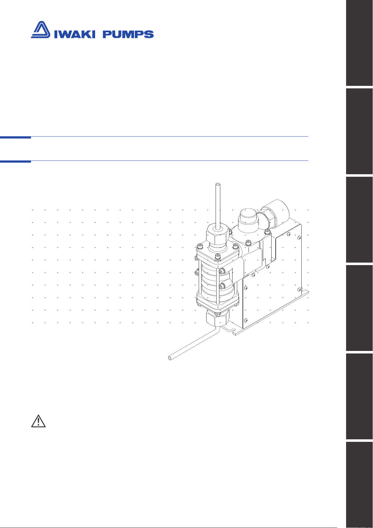
Photoresist Dispensing Pump
PDS-105 RA/RB
Safety instructions Overview Installation Operation Maintenance
Instruction manual
Thank you for choosing our product.
Please read through this instruction manual before use.
This instruction manual describes important precautions and instructions for the product. Always keep it on hand for quick reference.
©2011 IWAKI CO., LTD.
Specication
Page 2
Order conrmation
Open the package and check that the product conforms to your order. If any problem or
inconsistency is found, immediately contact your distributor.
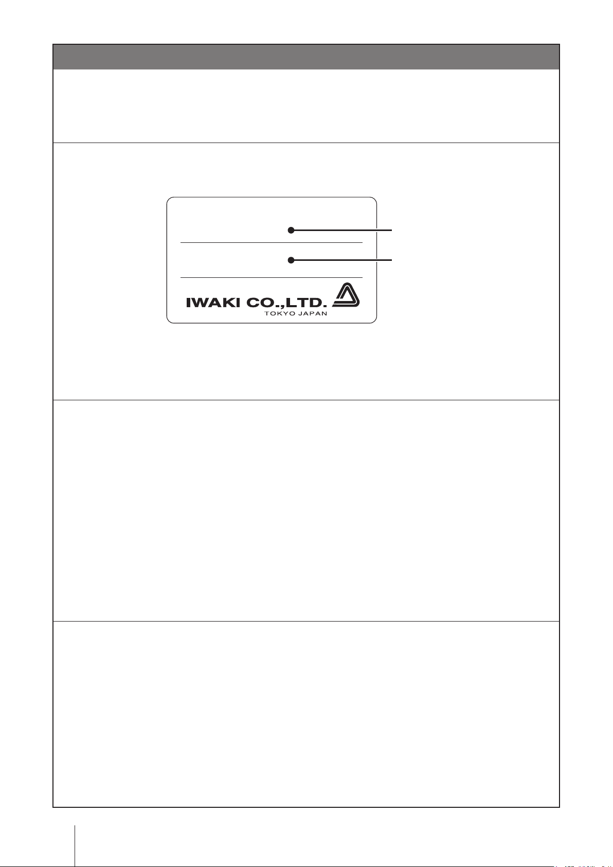
a. Check if the delivery is correct.
Check the nameplate to see if the information such as model codes and production number are as or-
dered.
MODEL
Model code
Production number
1P417431
b. Check if the required number of accessories is provided.
<Attached accessories>
• R-03-PB8F signal wire connector (one each)
• R-03-PB5F motor wire connector (one each)
c. Check if the delivery is damaged or deformed.
Check for transit damage and loose bolts.
Order conrmation
2
Page 3

Contents
Order conrmation .......................................................................................................................................... 2
Safety instructions .................................................................... 5
Warnings ........................................................................................................................................................ 6
Cautions ......................................................................................................................................................... 7
Precautions for use ...................................................................................................................................... 8
Overview .................................................................................... 9
Introduction ................................................................................................................................................... 9
Pump structure & Operating principle ........................................................................................................ 9
Discharge process ................................................................................................................................ 9
Suction process .................................................................................................................................. 10
Part names ................................................................................................................................................... 11
Identication codes .................................................................................................................................... 12
Installation ...............................................................................13
Before installation ....................................................................................................................................... 13
Installation/Piping/Wiring .......................................................................................................................... 14
Installation ................................................................................................................................................ 14
Piping ....................................................................................................................................................... 14
Wiring ....................................................................................................................................................... 15
Applicable motor drivers .......................................................................................................................... 16
Operation ..................................................................................17
Pump setting ............................................................................................................................................... 17
Pulse input & Motor rotation ..................................................................................................................... 17
Number of pulses & Flow volume ....................................................................................................... 17
Number of pulses & Flow rate ............................................................................................................. 17
Return to origin ......................................................................................................................................... 18
Home sensor output is "OFF" ............................................................................................................. 18
Home sensor output is "ON" ............................................................................................................... 18
Operation programming ........................................................................................................................... 18
Time based control (when using an Oriental Motor SG9200-2 pulse controller) ................................ 19
Flow based control (when using a pulse signal as a start signal) ....................................................... 20
Pump operation ........................................................................................................................................... 21
Contents
3
Page 4

Maintenance ............................................................................ 22
Troubleshooting .......................................................................................................................................... 22
Inspection .................................................................................................................................................... 23
Daily inspection ........................................................................................................................................ 23
Specication/Outer dimension .................................................................................................................. 24
Specication ............................................................................................................................................. 24
Pump ................................................................................................................................................... 24
Stepping motor .................................................................................................................................... 25
Encoder (RB type) ............................................................................................................................... 25
Home sensor ....................................................................................................................................... 25
Pressure sensor .................................................................................................................................. 25
Outer dimension ....................................................................................................................................... 26
PDS-105R A/B .................................................................................................................................... 26
4
Contents
Page 5
Safety instructions
Fire ban
Read through this section before use. This section describes important
information for you to prevent personal injury or property damage.
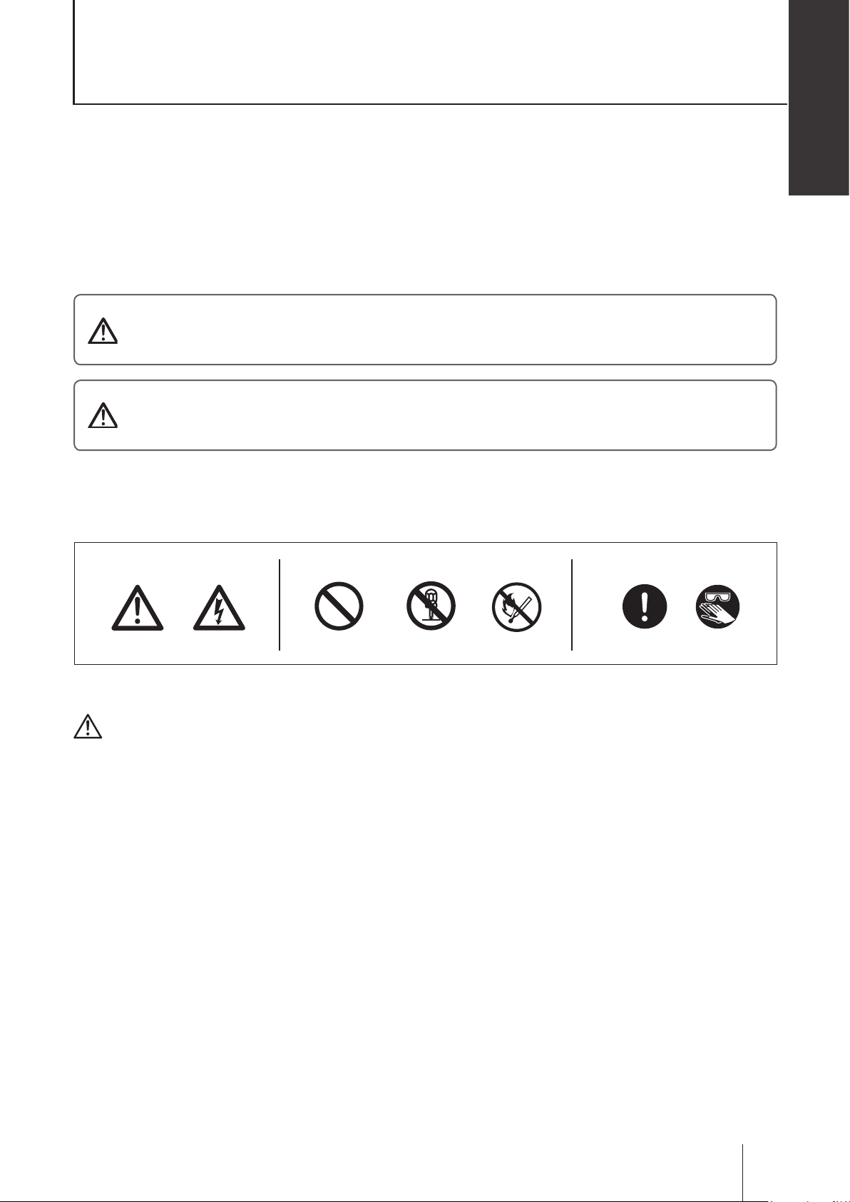
■ Symbols
In this instruction manual, the degree of risk caused by incorrect use is noted with the follow-
ing symbols. Please pay attention to the information associated with the symbols.
Indicates mishandling could lead to a fatal or serious
WARNING
CAUTION
accident.
Indicates mishandling could lead to personal injury or prop-
erty damage.
Safety instructions
A symbol accompanies each precaution, suggesting the use of "Caution", "Prohibited actions"
or specic "Requirement".
Caution marks Prohibited marks Requirement marks
Caution
Electrical
shock
Prohibited
Do not rework
or alter
Requirement
Wear
protection
Export Restrictions
Technical information contained in this instruction manual might be treated as controlled tech-
nology in your countries, due to agreements in international regime for export control.
Please be reminded that export license/permission could be required when this manual is
provided, due to export control regulations of your country.
Safety instructions
5
Page 6
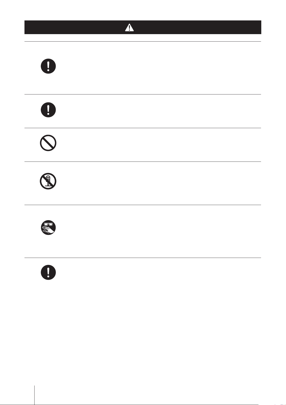
Requirement
WARNING
Turn off power before work
Risk of electrical shock. Be sure to turn off power to stop the pump and
related devices before service is performed. Let other people know about
the situation by displaying a notice such as "POWER OFF (Maintenance)"
near the power switch.
Stop operation
If you notice any abnormal or dangerous conditions, suspend operation
Requirement
Prohibited
Do not remodel
Wear
protectors
immediately and inspect/solve problems.
Do not use the pump in any condition other than its intended purpose
The use of the pump in any conditions other than those clearly specied
may result in failure or injury. Use this product in specied conditions only.
Do not modify the pump
Alterations to the pump carries a high degree of risk. It is not the manufac-
turer's responsibility for any failure or injury resulting from alterations to the
pump.
Wear protective clothing
Always wear protective clothing such as an eye protection, chemical re-
sistant gloves, a mask and a face shield during disassembly, assembly or
maintenance work. The specic solution will dictate the degree of protec-
tion. Refer to MSDS precautions from the solution supplier.
6
Requirement
WARNING
Spill precautions
Ensure protection and containment of solution in the event of plumbing or
pump damage (secondary containment).
Page 7
CAUTION
Qualied personnel only
The pump should be handled or operated by qualied personnel with a
Safety instructions
Requirement
Prohibition
Requirement
Prohibition
full understanding of the pump. Any person not familiar with the product
should not take part in the operation or maintenance of the pump.
Use specied power only
Do not apply any power other than that specied on the nameplate. Other-
wise, failure or re may result. Ensure the pump is properly grounded.
Ventilation
Fumes or vapours can be hazardous with certain solutions. Ensure proper
ventilation at the operation site.
Do not install or store the pump:
• In a ammable atmosphere.
• In a dusty/humid environment.
• In a corrosive atmosphere.
Flushing before operation
Requirement
Requirement
Requirement
Requirement
Flush the inside of the pump and piping with pure water or the liquid to be
delivered before the start of operation.
Static electricity
When low electric conductivity liquids such as ultra-pure water and fluor
TM
inactive liquid (e.g. Fluorinert
) are handled, the static electricity may be
generated in the pump and may cause static discharge. Take counter-
measures to remove the static electricity.
Before returning product
Be sure to drain chemicals and clean the inside of the pump before return
so that a harmful chemical does not spill out in transit.
Disposal of a used pump
Dispose of any used or damaged pump in accordance with relevant regu-
lations. Consult a licensed industrial waste products disposing company.
CAUTION
7
Page 8

Precautions for use
• Electrical work should be performed by a qualied electrician. Otherwise,
personal injury or property damage could result.
• Do not install the pump:
–In a ammable atmosphere.
–In a dusty/humid place.
– In a corrosive atmosphere.
• Allow sufficient space around the pump for easy access and maintenance.
• Use care handling the pump. Do not drop. An impact may affect pump
performance. Do not use a pump that has been damaged to avoid the risk
of electrical damage or shock.
Caution
Caution
Caution
• The pump is not waterproof. Do not operate the pump while wet with solu-
tion or water. Failure or injury may result. Immediately dry off the pump if it
gets wet.
• Do not close discharge line during operation. Solution may leak or piping
may break.
• Solution in the discharge line may be under pressure. Release the pres-
sure from the discharge line before disconnecting plumbing or disassembly
of the pump to avoid solution spray.
• Wear protective clothing when handling or working with pumps. Consult
solution MSDS for appropriate precautions. Do not come into contact with
residual solution.
Caution
Caution
Requirement
Caution
Precautions for use
8
Page 9
Overview
Pump working principle, part names and identication codes are described in this section.
Introduction
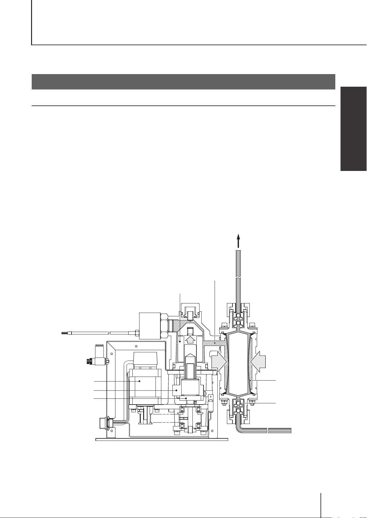
Pump structure & Operating principle
The rotational motion of the stepping motor is changed to linear motion by the direct drive unit. Liquid is loaded
into the pump head and then delivered to a discharge line as the bellows reciprocates.
Principle of operation
● The bellows expands and contracts as the ball screw reciprocates.
● The reciprocating motion of the bellows compresses or expands the shape of the tubephragm via hydraulic
uid.
● Volumetric change is created in the tubephragm.
● Liquid is taken in as the tubephragm expands and is pushed out as it contracts in sync with the action of the
check valves (pump head valves).
Overview
■ Discharge process
Stepping motor
Cylinder
Ball screw
OUT
Hydraulic fluid
Bellows
Tubephragm
Check valve
Introduction
9
Page 10

■ Suction process
IN
10
Introduction
Page 11

Part names
Pressure sensor
Monitors hydraulic pressure.
Outlet
Overview
Base
Always anchor it with bolts.
Speed controller joint
Used for air purge.
Motor-Driver wiring terminal
Used for connecting a motor driver.
Inlet
Nameplate
Signal line terminal
Used for connection with user's PLC.
*Do not clean the pressure sensor, speed controller or nameplate with a solvent such as benzine or thinner.
Shows a model code and MFG number.
Part names
11
Page 12

Identication codes
Each code represents the following information.
PDS - 1 05 RA - K T W2 - 01
a b c d e f g h
a. Series name
b. Product classication
1: Pump
c. Flow rate
05: 5.0ml/shot (max discharge capacity)
d. Drive unit
RA: Compact type (with no encoder)
RB: Compact type (with an encoder)
e. Wet end O ring
K : Kalrez®
f. Pressure sensor
P : Positive pressure sensor (0-1000kPa)
T : Compound pressure sensor (-100 - 300kPa)
g. Inlet/outlet I.D.
W2: 1/4" (ø6.35×ø4.35mm) PFA tube connection
M6: ø6×ø4 [mm] PFA tube connection
h. Special version
No code: Standard
01: Custom design (coded in ascending order)
Identication codes
12
Page 13

Installation
This section describes the installation of the pump, piping and wiring. Read through
this section before work.
Points to be observed
Observe the following points when installing the pump:
• Be sure to turn off power to stop the pump and related devices before service is performed.
• Be careful for the power not to be turned on while service is performed.
• If you notice any abnormal or dangerous conditions, suspend operation immediately and
inspect/solve problems.
• Do not install the pump in a ammable atmosphere.
Observe the following points during wiring work:
Electrical work should be performed by a qualied electrician. Always observe applica-
•
ble codes or regulations.
Do not perform wiring work while the power is on. Otherwise, an electrical shock or
•
short circuit may result. Be sure to turn off power before wiring work.
Be careful for the power not to be turned on during work.
•
Installation
Before installation
A driver in a user's PLC and other related devices are necessary for operation. Purchase
these devices including a motor driver separately as needed. The following diagram is a gen-
eral system example. Congure your system in accordance with an actual service condition.
User's PLC
Controller
Solenoid valve
Motor driver
Air-operated
Pump
valve
Nozzle
Silicon wafer
Chemical liquid
Before installation
13
Page 14

Installation/Piping/Wiring
NOTE
Do not hold the pump head to lift the pump unit up, or the pump head may deform and a leak may result.
Installation
Observe the following points during installation.
● Installation location
Mount the pump indoors. Allow sufcient space around the pump for easy access and maintenance.
● Mounting position
• Install the pump as close to a supply tank as possible in a ooded suction system.
• Make sure the discharge-line end-nozzle is positioned higher than a chemical liquid level.
Nozzle
Chemical liquid
● Mounting direction
Always direct the outlet upward. Keep the pump head in a vertical position with the check valves upright.
Otherwise, performance may be reduced.
● Anchoring
Fix the pump with four M4 mounting screws (with PW and SW).
Piping
Observe the following points during pipework.
● Pipe connection
Both inlet and outlet of the pump have PFA tube joints. Secure every joint properly to eliminate any possibility
of air ingress, or performance may be reduced.
● Fitting and Tube
Take account of corrosion and pressure resistance when selecting ttings and tubes.
● Pipe resistance
Keep a piping length shortest with the minimum number of bends.
Installation/Piping/Wiring
14
Page 15

Wiring
Observe the following diagram.
24VDC
SG9200-2 Pulse Controller
PLC
GND
YesNo
Use of a pulse controller:
24VDC
10 11 12
1 2 3 4 5 6 7 8 9
CN2
1
3
2
CN1
ORIENTAL MOTOR
CSD5807N2-P driver
GND
1 2 3 4 5
CN3
Terminal assignment
Driver connector PIN1 (Blue motor lead)
Driver connector PIN2 (Red motor lead)
Driver connector PIN3 (Orange motor lead)
Driver connector PIN4 (Green motor lead)
Driver connector PIN5 (Black motor lead)
A
B
No.
Motor line connectors
E
C
D
Installation
Input of a pulse signal rotates the motor clockwise
(seen from the motor output shaft).
Input of a pulse signal rotates the motor counterclockwise
(seen from the motor output shaft).
CW pulse input
−
1
2
CCW pulse input
+
−
3
4
+
Motor driver CN2 terminal assignment
● Photocoupler ON: HALF Step
When at “photocoupler is ON”, the current to the motor stops,
All Windings
+
5
● Photocoupler OFF: FULL Step
allowing the motor shaft to be rotated by hand.
Signal
Off Signal
Step Angle
−
+
−+−
6
7
8
● A signal is output whenever the motor excitation sequence
returns to step “0” in synchronization with the input pulse signal
● Photocoupler ON: Automatic Current Cutback Release
Automatic Current
Cutback Release Signal
9
10
(output transistor is ON).
Excitation Timing
+
11
Encoder A phase + Line driver output
Terminal assignment
A
No.
Signal line connectors
● A signal is output every 10 pulses in full step mode and every
20 pulses in half step mode.
Signal
−
12
Encoder A phase - Line driver output
B
GND (common)
Encoder B phase + Line driver output
C
Sensor output (open collector)
Encoder B phase - Line driver output
D
5-24VDC (home sensor power)
5VDC (encoder power)
F
E
H
G
Note: An encoder is equipped only to the B type.
*When using an Oriental motor SG9200-2 pulse controller, consult its instruction manual as well.
Wiring Diagram
Installation/Piping/Wiring
15
Page 16

Applicable motor drivers
See the table below for applicable ORIENTAL MOTOR's motor drivers.
Product name
CR D5107PB 24VDC
CR D507- K D 24VDC Built in
Rated power
voltage
Driver type
Pulse-train
input
Pulse input
type
1 pulse/
2 pulse
(I/O,
RS485)
Driver type Cable Attached connector
PCB
BOX
• Cable set
LCS04SD5 (0.6m)
• Motor lead connector
LCS5N06B (0.6m)
LCS5N10B (1m)
<Accessories>
• In/out cable connector
• Motor lead connector
• MOREX 51103-0200
• MOREX 51103-1200
• MOREX 51103-0500
• MOREX 50351-8100 (contact)
• PHOENIX CONTACT MC1,5/3STF-3,5 power line connector
CSD5807N-P 24VDC
SD 5107P3 24VDC
RK D507- A 100VAC
Pulse-train
input
Pulse-train
input
Pulse-train
input
2 pulse PCB
2 pulse PCB
1 pulse/
2 pulse
BOX
• Driver cable set
LCS01CSK5 (0.6m)
• Driver cable set
LCS04SD5 (0.6m)
• Motor lead connector
LC5N06B (0.6m)
LC5N10B (1m)
CC05PK5 5m motor cable
CC10PK5 10m motor cable
CC20PK5 20m motor cable
• AMP 171822-3
• AMP 1-171822-2
• AMP 171822-5
• MOREX 51103-0200
• MOREX 51103-1200
• MOREX 51103-0500
• MOREX 50351-8100 (contact)
• Control signal in/out connector
Case: MOREX 54311-1201
Connector: MOREX 54306-2019
Installation/Piping/Wiring
16
Page 17

Operation
This section describes pump operation. Observe instructions in this manual. See manufacturer's instruction manual for the motor driver.
Pump setting
First, program operation of the pump.
Pulse input & Motor rotation
The pump lets out liquid at the input of the CCW direction command pulse and takes in liquid at the input of the
CW direction command pulse.
At factory default setting, the motor-driven cylinder (sensor dog) is at the origin where a home sensor output
turns ON. Be sure the cylinder returns to the origin before operation. See the next page for detail.
■ Number of pulses & Flow volume
Number of input pulses Calculated ow volume
2400 1ml
4800 2ml
7200 3ml
9600 4ml
12000 5ml
■ Number of pulses & Flow rate
Number of input pulses per sec Calculated ow rate
2400 pps 1ml/sec
4800 pps 2ml/sec
7200 pps 3ml/sec
9600 pps 4ml/sec
Operation
Pump setting
17
Page 18

Return to origin
Program the origin return behaviour to ensure the motor-driven cylinder to come back to origin before opera-
tion every day. The behaviour should be different depending on whether the home sensor output is ON or OFF
at an input of an origin return signal. See the programming chart below for detail.
■ Home sensor output is "OFF"
Input of an origin return
signal (from PLC)
Home sensor output
signal (from pump)
Pump behaviour
Discharge
process
Suction
process
Origin
Offset interval (max 600 pulses from origin)
■ Home sensor output is "ON"
Input of an origin return
signal (from PLC)
Home sensor output
signal (from pump)
Pump behaviour
Discharge
process
Suction
process
Origin
Offset interval (max 600 pulses from origin)
Operation programming
Operational behaviour can be programmed into two different control modes; Time-based control (via a pulse
controller) and Flow-based control (via a pulse controller or user's PLC). In either mode, the pump runs through
the routine of a discharge process, pause state, suction process and waiting state. See the following charts to
program operation in individual modes.
NOTE
• The cylinder can contract beyond the origin for the offset interval (600 pulses below the origin). Do not ex-
ceed the limit.
• The motor may step out if the waiting time is too short. "Step out" means the motor rotates out of a specified
step angle and number of pulses.
• The maximum discharge flow rate is 4ml/sec, however, discharge pressure may rise sharply depending on liquid
viscosity and piping layout, and may overload the bellows. Observe the maximum discharge pressure.
• The maximum suction flow rate is 3ml/sec, however, suction pressure may fall sharply depending on liquid vis-
cosity and piping layout, and may trigger cavitation. Reduce the flow rate as necessary.
18
Pump setting
Page 19

■ Time based control (when using an Oriental Motor SG9200-2 pulse controller)
An ORIENTAL MOTOR SG9200-2 pulse controller is needed for discharge-time control and an OMROM
H3RN-1 Off-delay timer for suction-time control. A discharge process is made for a discharge time; a time period
when the pump is receiving the discharge signal from the pulse controller, and a suction process starts as re-
ceiving a suction signal from the Off-delay timer. Provide with the pulse controller a pause time [T1] of 0.5 sec or
more between the end of a discharge process and the start of a suction process and a waiting time (at least 1/2
of a set suction time) [T2] between the end of the suction process and the start of the next discharge process.
NOTE
Observe the formula below when determining a discharge ow rate and a discharge time. Or the pump may break:
Discharge ow rate (see page 24) × Discharge time = 5.0ml (max disch. capacity per shot: see page 24) or less
<When a discharge ow rate × a discharge time = 5.0ml>
Discharge signal
(from pulse controller)
Home sensor output signal
(from pump)
Valve delay (user-selectable)
Control signal of discharge-
line air-operated valve
(valve ON during signal input)
Suction signal
(from Off delay timer)
Pump behaviour
Discharge
process
Suction
process
Pause time [T1] : 0.5 sec or more
<When the same discharge ow rate × a discharge time < 5.0ml>
A discharge process will becomes shorter.
Discharge signal
(from pulse controller)
Home sensor output signal
(from pump)
Valve delay (user-selectable)
Operation
Waiting time [T2] : 1/2 of suction time or more
Control signal of discharge-
line air-operated valve
(valve ON during signal input)
Suction signal
(from Off delay timer)
Discharge
Pump behaviour
process
Suction
process
Pause time [T1] : 0.5 sec or more
Discharge time
Waiting time [T2] : 1/2 of suction time or more
Pump setting
19
Page 20

■ Flow based control (when using a pulse signal as a start signal)
Use the pulse controller or user's PLC to program a discharge and a suction ow rate as well as a pause time
[T1] of 0.5 sec or more between the end of a discharge process and the start of a suction process and a wait-
ing time (at least 1/2 of the time taken to nish suction process per set ow rate) [T2] between the end of the
suction process and the start of the next discharge process as well. The programmed behaviour starts at an
input of pulse signal.
(from pulse controller/PLC)
Control signal of discharge-
Pump behaviour
Pulse signal
Home sensor output signal
(from pump)
line air-operated valve
(opens during signal input)
Discharge
process
Suction
process
Valve delay (user-selectable)
Precedent valve close (user-selectable)
Pause time [T1] : 0.5 sec or more
Waiting time [T2] : 1/2 of suction time or more
20
Pump setting
Page 21

Pump operation
Filter ushing
1
Check that lter has been ushed in user's system.
NOTE
See manufacturer's manual for lter ushing.
Degassing
2
Eliminate air from the lter cartridge before operation. Air in a lter or a pipeline reduces a ow rate.
NOTE
See manufacturer's manual for degassing.
Open a suction and a discharge line fully.
3
NOTE
Do not close a valve on a suction line or a discharge line during operation. It may pose a leak or blow
out the pump or a pipe.
Operation
4
Start operation along a programmed behaviour.
Operation
Pump operation
21
Page 22

Maintenance
This section describes troubleshooting, inspection, specication and dimensions.
Points to be observed
Observe the following points during maintenance work:
• Follow instructions in this manual for replacement of wear parts. Do not disassemble the
pump. Contact us when repairs are needed.
• Always wear protective clothing such as an eye protection, chemical resistant gloves, a
mask and a face shield during disassembly, assembly or maintenance work. The specific solution will dictate the degree of protection. Refer to MSDS precautions from the
solution supplier.
• Solution in the discharge line may be under pressure. Release the pressure from the
discharge line before disconnecting plumbing or disassembly of the pump to avoid solution spray.
• Risk of electrical shock. Be sure to turn off power to stop the pump and related devices
before service is performed.
Troubleshooting
First check the following points. If the following measures do not help remove problems, contact your distributor.
States Possible causes Check items Solutions
The pump
does not run.
Liquid can not
be pumped up.
* Solutions marked with * are conducted by us.
Faulty wiring If wiring between the motor and mo-
tor driver is correct? See page 15.
Power voltage is too
low.
An inapplicable mo-
tor driver is used.
Motor failure If the motor steps out, abnormal
Air ingress through a
suction line
A failed O ring seal Check for a leak point or a loose
Clogging in a pipe or
the pump
Malfunction of an air-
operated valve
A ball valve is stuck
on a valve seat.
If a rated power voltage is applied
to the motor driver? See page 16.
If an applicable motor driver is
used? See page 16.
noise and vibration are found?
Check for an air-ingress point. • Seal the point by tightening a
bolt.
Flush the pipe and the pump to
determine clogging points.
If supply air pressure is correct? • Observe the rated supply air
If a solenoid valve is damaged? • Replace as necessary.
If liquid ows back from the suction
line end.
• Correct wiring and resume opera-
tion.
• Observe the rated voltage of the
driver.
• Use an applicable motor driver.
• Check the motor. Replace as
necessary.*
If motor has failed, related electric
devices may also have failed, so
inclusive inspection is necessary.
pipe joint.
• Tighten the bolt. Replace O ring
as necessary.*
• Determine a cause of clogging.
Repair will be needed if the pump
is clogged.*
pressure.
• Replace the check valve as nec-
essary.*
Troubleshooting
22
Page 23

States Possible causes Check items Solutions
No home sen-
sor signal
No pressure
sensor signal
No encoder
signal
* Solutions marked with * are conducted by us.
Faulty wiring If the signal and power lines are
connected in place? See page 15.
Home sensor failure Use a tester to check the voltage
between GND and signal output
terminals. The result should be:
0V at sensor "ON"
Power voltage at sensor "OFF"
Faulty wiring If the signal and power lines are
connected in place? See page 15.
Pressure sensor fail-
ure
Faulty wiring If the signal and power lines are
Encoder failure A counter does not work. • Replace as necessary*
Use a tester to check the voltage
between GND and signal output
terminals. The result should be:
1V when pump is stopped
Above 1V when pump is running
connected in place? See page 15.
• Correct wiring and resume opera-
tion.
• Replace as necessary*
• Correct wiring and resume opera-
tion.
• Replace as necessary*
• Correct wiring and resume opera-
tion.
Inspection
Perform daily inspection to keep pump performance and safety.
Daily inspection
Check for a leak or any other abnormality during operation. If you notice any abnormal condition, suspend
operation immediately and inspect/solve problems according to "Troubleshooting".
Maintenance
Inspection
23
Page 24

Specication/Outer dimension
Specication
Information in this section is subject to change without notice.
■ Pump
Item Spec
Max discharge capacity 5.0 [ml/shot]
Max discharge pressure*
4&6
Pressure resistance 300 [kPa]
Discharge ow rate 0.1-4.0 [ml/sec]
Suction ow rate*
1
Resolution 0.01 [ml]
Discharge accuracy ±0.3 [%]F.S
Linearity*
5
Allowable liquid viscosity Max.200 [mPa·s]
Allowable surface temperature*
Number of pulses per discharge capacity*
2
3
Ambient temperature 10-40 [ºC]
Ambient humidity 30- 45 [%RH]
Allowable liquid temperature 15-25 [ºC]
Weight 3 [kg]
*1 Suction pressure may be too low (negative) and trigger cavitation depending on operating conditions such as liquid
viscosity, piping layouts and suction flow rate (max. 3ml/sec). Adjust the suction flow rate as necessary.
*2 The allowable surface temperature is based on operation at ambient of 22±1ºC, with full stroke length and 1 shot/min.
*3 The number of pulses per discharge capacity is a reference value with half stepping (0.36° per pulse).
*4 Set the discharge ow rate not to exceed the max discharge pressure.
*5 When handling viscous liquid, linearity may reduce depending on piping layout. In this case linearity can be maintained
by closing a discharge-side air operated valve after liquid is completely discharged. Determine an optimal delay time in
accordance with operating conditions.
*6 Do not close a valve on a suction line or a discharge line during operation. It may pose a leak or blow out the pump or a
pipe.
150 [kPa]
0.1-3.0 [ml/sec]
±0.5 [%]F.S
Max.30 [ºC]
2400 [pulse/ml]
Specication/Outer dimension
24
Page 25

■ Stepping motor
Items Spec
Manufacturer ORIENTAL MOTOR Co, Ltd.
Model PK545-NB or equivalent
Maximum holding torque 0.23 N·m
Rated current 0.75 A/Phase
Step angle 0.72°
Insulation resistance B class (130ºC)
The above date is based on use of an ORIENTAL MOTOR CSD5807N2-P driver.
■ Encoder (RB type)
Items Spec
Manufacturer Microtech Laboratory Inc.
Model MGH-20-500-E
Supply voltage 5 VDC ± 0.5
Consumption current 60 mA or below
Detection Incremental
Number of output pulses 500
Output phase 2-phase (A and B)
Output type Line driver
■ Home sensor
Items Spec
Manufacturer OMRON
Model EE-SX670A
Supply voltage 5-24 VDC ± 10%
Sensor logic Normally open
Output type Open collector
Dark-ON
Output operation
■ Pressure sensor
Manufacturer Nidec Copal Corporation
Rated pressure
Supply voltage 10.8-30 VDC
Consumption current 20 mA or below
Output type
Pilot lamp
Sensor
Items Spec
Model
PA-850-103G-NGF
PA-850-302R-NGF
103G: 0-1000 kPa
302R: -100 - 300 kPa
Analogue voltage
Main circuit
Pressure
Sensor
Power voltage +
L (not used)
Sensor out
Common -
Power voltage + (brown)
Analogue out (white)
Switch out (black)
Specication
Common - (blue)
Earth (shielded)
Output voltage 1-5 VDC
Specication/Outer dimension
25
Page 26

Outer dimension
■ PDS-105R A/B
(2000)
(182)
105
60
OUT
(100)(182)
23
44
30
Tube size
W2 1/4" PFA tube
M6 ø6×ø4 PFA tube
(189)
175
7 161
(R)
213.5
(100)
IN
44
30
13.5
50
Specication/Outer dimension
26
Page 27

27
Specication
Page 28

Australia IWAKI Pumps Aust ralia Pty. Ltd.
Austria IWAKI EUROPE Gmb H
Belgium IWAKI Belgium n.v.
China IWAKI Pumps (Shanghai) Co., Ltd.
China IWAKI Pu mps (Guandong) Co., Ltd.
China
China
GFTZ I WAKI Engine ering & Trading (Gu angzhou)
GFTZ I WAKI Enginee ring & Trading (Be ijing)
Denmark IWAKI Nordic A/S
Finland IWAKI Suomi Oy
France IWAK I France S.A.
Germany IWAKI EUROPE GmbH
Holland IWAKI EUROPE NL Branch
Hong Kong IWAKI Pumps Co., Ltd.
Indonesia
IWAKI Si ngapore (I ndonesia Br anch)
TEL : (61)2 9899 2411 FAX : 2 989 9 2421
TEL : (49)2154 925 4 0 FAX : 2154 925 4 48
TEL : (32)1367 0200 FAX : 1367 203 0
TEL : (86)21 627 2 7502 FAX : 21 6272 69 29
TEL : (86)750 38 66228 FAX : 750 38 66278
TEL : (86)20 8 435 0603 FAX : 20 84 35 9181
TEL : (86)10 64 42 7713 FAX : 10 6442 7712
TEL : (45)4 8 24 2345 FAX : 48 24 2 346
TEL : (358)9 2 745810 FAX : 9 2742715
TEL : (33)1 69 63 3 3 70 FA X : 1 64 49 92 73
TEL : (49)2154 925 4 0 FAX : 2154 925 4 48
TEL : (31)547 293 160 FAX : 547 292 3 32
TEL : (852)2 6 07 1168 FAX : 2 607 1000
TEL : (62)21 69 0 6606 FAX : 21 690 6 612
IWAKI CO.,LTD. 6-6 Kanda-Sudacho 2-chome Chiyoda-ku Tokyo 101-8558 Japan
Italy IWAKI Italia S.R.L .
Korea IWAKI Korea Co.,Ltd.
Malaysia IWAKIm Sdn. Bhd.
Norway IWAKI Norge AS
Singapore IWAKI Singapore Pte. Ltd.
Spain IWAKI Iberica Pumps, S.A .
Sweden IWAKI Sverige AB
Switzerland IWAKI (Schweiz) AG
Tai wan IWAKI Pumps Taiwan Co., Ltd.
Tai wan
IWAKI Pu mps Taiwan (Hsin -chu) Co., Ltd . TEL : (886)3 57 3 5797 FAX : (8 86)3 573 5798
Thailand IWAKI (Thailand) Co.,Ltd.
U.K. I WAKI Pumps (UK) LTD.
U.S.A . IWAKI AMERICA Inc.
Vietnam IWAKI pumps Vietnam Co.,Ltd.
TEL:(81)3 3254 2935 FAX:3 3252 8892
TEL : (39)0 444 371115 FAX : 0 444 335 350
TEL : (82)2 263 0 4800 FA X : 2 2630 4801
TEL : (60)3 78 03 8807 FA X : 3 7803 480 0
TEL : (47)23 38 49 0 0 FAX : 23 3 8 49 01
TEL : (65) 6316 2028 FAX : 6316 3221
TEL : (34)9 43 630030 FAX : 943 6 28799
TEL : (46)8 511 72900 FAX : 8 511 72922
TEL : (41)26 674 9300 FAX : 26 674 9302
TEL : (886) 2 8227 6900
TEL : (66)2 32 2 2471 FAX : 2 32 2 2477
TEL : (44)1743 231363 FAX : 1743 366507
TEL : (1)508 429 1440 FAX : 508 42 9 1386
TEL : (84)613 933 456 FAX : 613 93339 9
( )Country codes
FAX : 2 8227 6 818
T787-1 '12/10
 Loading...