

Page 1
IWAKI Auto-Dampener
PDA-W
Instruction Manual
Read this manual before use of product
This is patent pending product
.
Page 2

We thank you for selecting IWAKI Auto-dampener PDA-W series. This instruction
manual, which is divided into five sections of "Safety", "Outline of product", "Instal-
lation", "Operation" and "Maintenance", deals with the correct handling and opera-
tion procedures for the auto-dampener. To make maximum use and to ensure safe
and long time operation of the auto-dampener, please read this manual thoroughly
and carefully prior to operating the auto-dampener.
Contents
Safety section
.................................................................................................
Outline of product
1. Unpacking and inspection
2. Outline of product
3. Model code
4. Specification
5. Dimensions and mass
6. Structure and names of parts
7. Main parts and labelling
Installation
...................................................................................................
1. Before use
2. Installation
3. Piping
Operation
...................................................................................................
1. Preparation for operation
2. Operation
3. Stopping
Maintenance
..................................................................................................
1. Troubleshooting
2. Maintenance and inspection
3. Consumable parts
...........................................................................................
..............................................................................
...............................................................................................
............................................................................................................
.........................................................................................................
......................................................................................
.......................................................................
...................................................................................
............................................................................................................
............................................................................................................
....................................................................................................................
.............................................................................
.............................................................................................................
.................................................................................
.......................................................................
....................................................
...................................................................
1
4
5
5
5
6
7
8
9
10
11
11
12
14
15
15
16
17
18
19
19
This instruction manual should be kept on hand by end users for quick reference. It is recommended that each user, after reading the instruction manual thoroughly, keep it in a position close to the pump system and where it may be easily accessed by operator at any time
whenever necessary.
Contact us if you have any questions.
Page 3
Important instruction
For the Safe and Correct Handling of the Auto-dampener
● Before use of the auto-dampener, read this "Safety Section" to prevent accidents and to avoid the
damage or loss of assets.
● Observe and abide by the instructions described in this "Safety Section".
These instructions are very important for protecting pump users or other persons from hazard or
loss of assets.
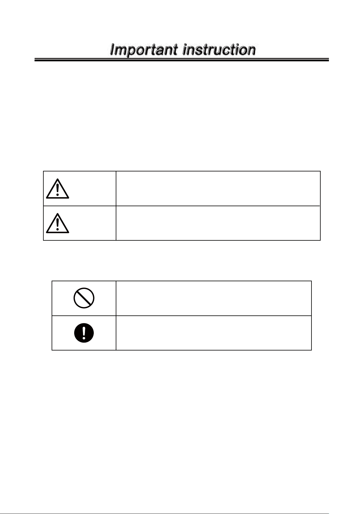
● Meaning of symbols
Following two symbols describe the extent of hazards and loss which may be brought if the
instructions are not observed or if the auto-dampener is wrongly used.
Non observance or misapplication of the contents of the
Warning
Caution
"Warning" could lead to death or injury.
Non observance or misapplication of the contents of the
"Caution" could lead to injury or damage.
Types of Symbols
Prohibited action or procedure is indicated.
Inside or near this circle, a concrete activity to be prohibited is
depicted.
Action or procedure which must be performed without fail is
indicated. Inside this circle, a concrete activity to be performed
is depicted.
-
1 -
Page 4
Safety instruction
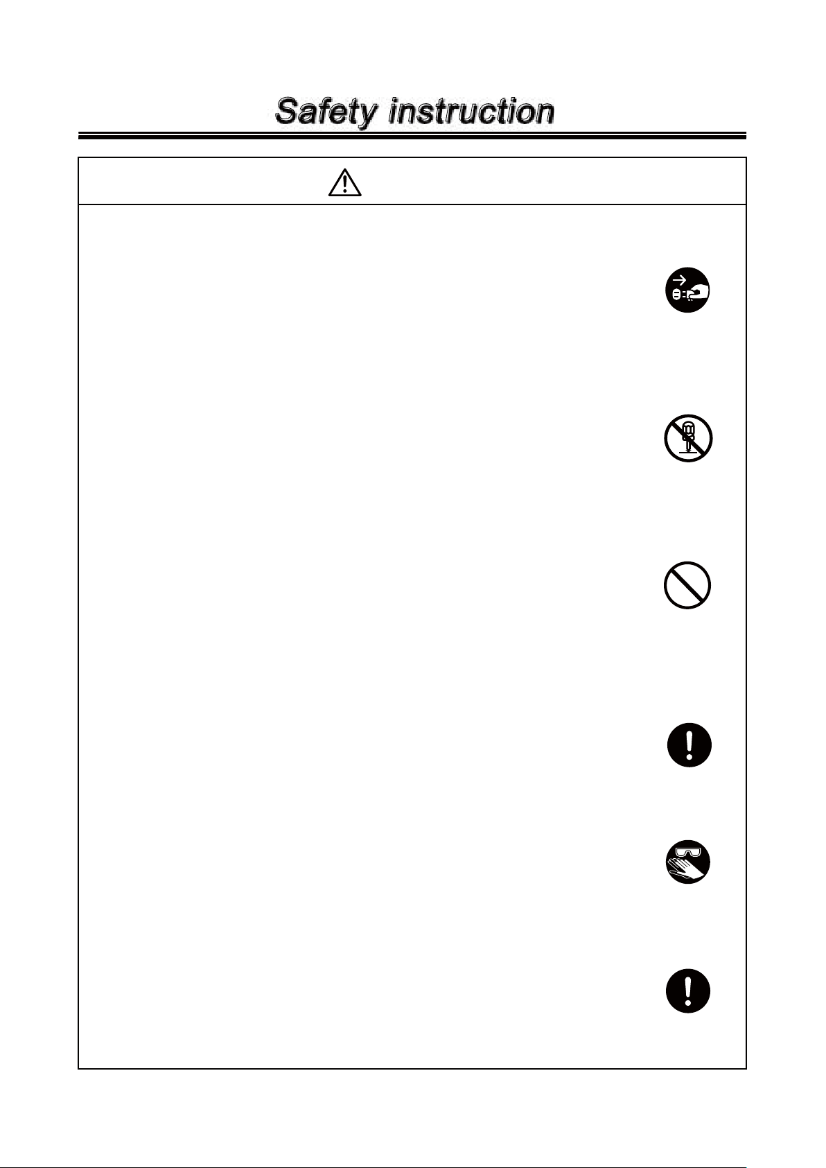
WARNING
● Power off
Be sure to turn off power prior to any inspection/maintenance and
installation works. Be careful power is not turned on unintentionally
while working on the dampener. In a noisy or dark place, display a sign
of "Men Working" near the power supply switch.
● Do not remodel the auto-dampener
Never remodel the auto-dampener. Remodeling may cause serious
injury or damage due to electrical shock. We are not responsible for
any accident or damage arise from modification.
● Prohibited installation/storage place
To avoid fire or injury, do not install or store the dampener in:
• Flammable atmosphere.
• Dusty place.
• Corrosive atmosphere.
Power off
No remodeling
Prohibited
● Ventilation
Risk of poisoning. Keep your working site ventilation when handling a
toxic/odoriferous liquid.
● Wear protective clothing
Be sure to wear protective clothing such as safety goggles, protective
gloves etc. during maintenance and/or inspection.
● Returns
When the dampener is sent back to IWAKI, drain the liquid out of the
dampener and clean thoroughly with water to prevent any accidents in
transportation.
-
2
-
Wear protective
gear
Page 5
Safety instruction
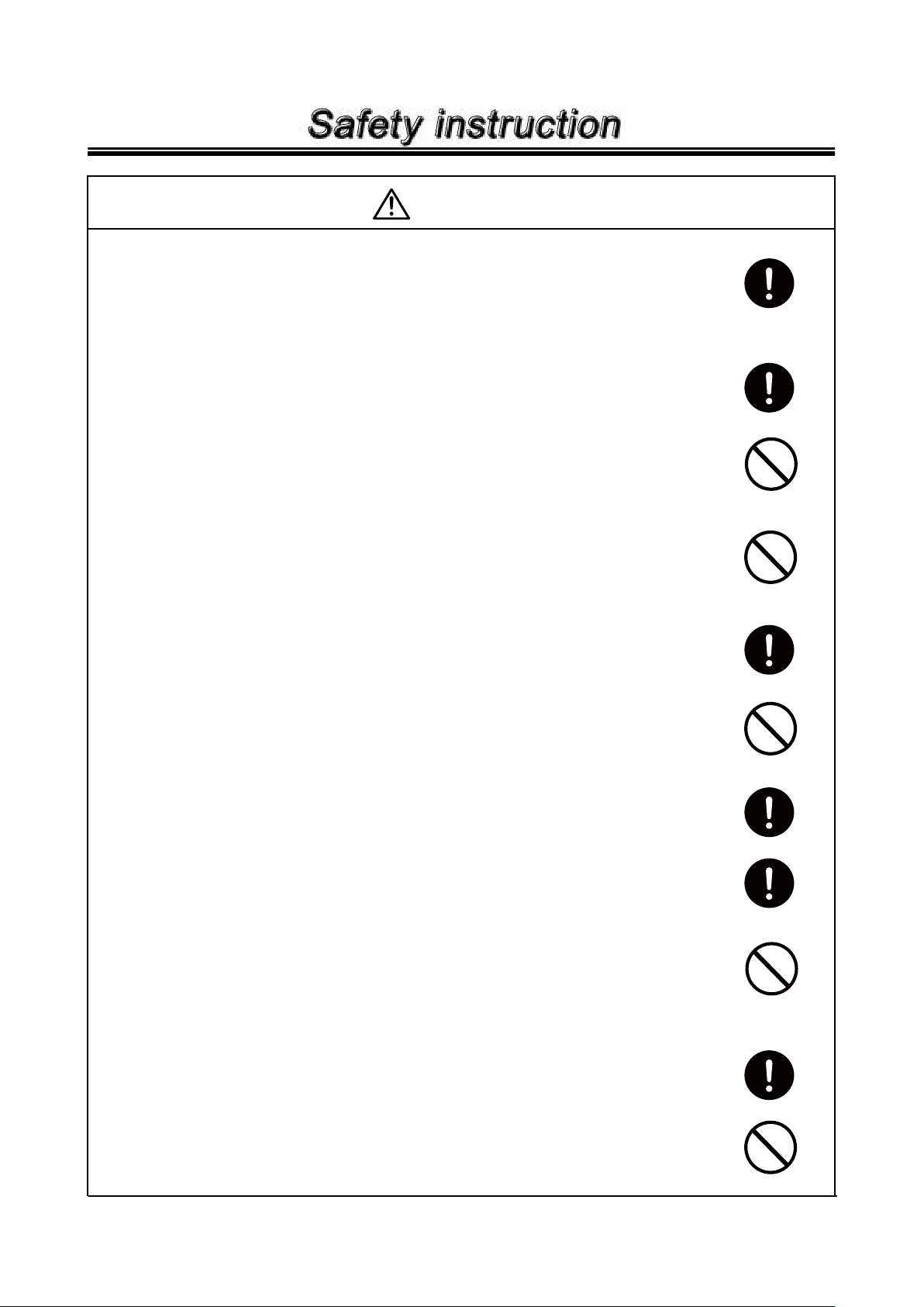
CAUTION
● Countermeasure against static electricity
When low electric conductivity liquid such as the ultra-pure water and
the fluor inactive liquid (e.g. Fluorinert™) are handled, static electricity
may generate in the pump, which may cause a static discharge and the
pump breakage. Take a countermeasure for removing static electricity.
● When pump is stopped
• When pump is stopped, release pressure on the discharge side first.
Otherwise the bellows may be deformed due to the residual pressure
on the pump discharge side.
• If a valve is provided on the discharge side, do not close the valve
when pump is stopped to avoid impactive pressure resulting in deformation of bellows or connecting plate.
● Pump at halt
• Do not supply air to both the right and left air-supply ports at the same
time to prevent the bellows from deformation.
• If the pump or dampener is stopped for a long time with the liquid
inside, the gas may be generated to penetrate the bellows and corrode the metallic parts. When the pump or dampener is stopped for 2
days or more, operate them for about 10 minutes a day to replace the
air.
Prohibited
Prohibited
● Air exhaust port
Do not choke (make tube dia. smaller) air exhaust port to avoid bellows
deformation due to residual air.
● Before operating the pump & dampener
Fully open pump suction and discharge valves. Confirm that liquid is
filled in piping.
● Supply air pressure
Do not supply air exceeding 0.5 MPa to prevent bellows from deformation.
● Prohibited liquids
Do not handle the following liquids.
• Liquid easily crystallizes
• Liquid containing slurry
• Solvent naphtha, stripping agents or solvents
● Disposal of used dampener
Disposal of used or damaged dampener must be done in accordance
with local laws and regulations. (Consult a licensed industrial waste
products disposing company.)
● Do not close a discharge valve which is positioned beyond the
dampener in operation.
Impactive pressure may deform the pump and dampener.
Prohibited
Prohibited
Prohibited
-
3 -
Page 6

Product outline
1. Unpacking and inspection
2. Outline of product
3. Model code
4. Specification
5. Dimension and mass
6. Structure and names of parts
7. Main parts and labelling
-
4
-
..................................................
................................................
.......................................
........................
.................................
............................
..................
5
5
5
6
7
8
9
Page 7
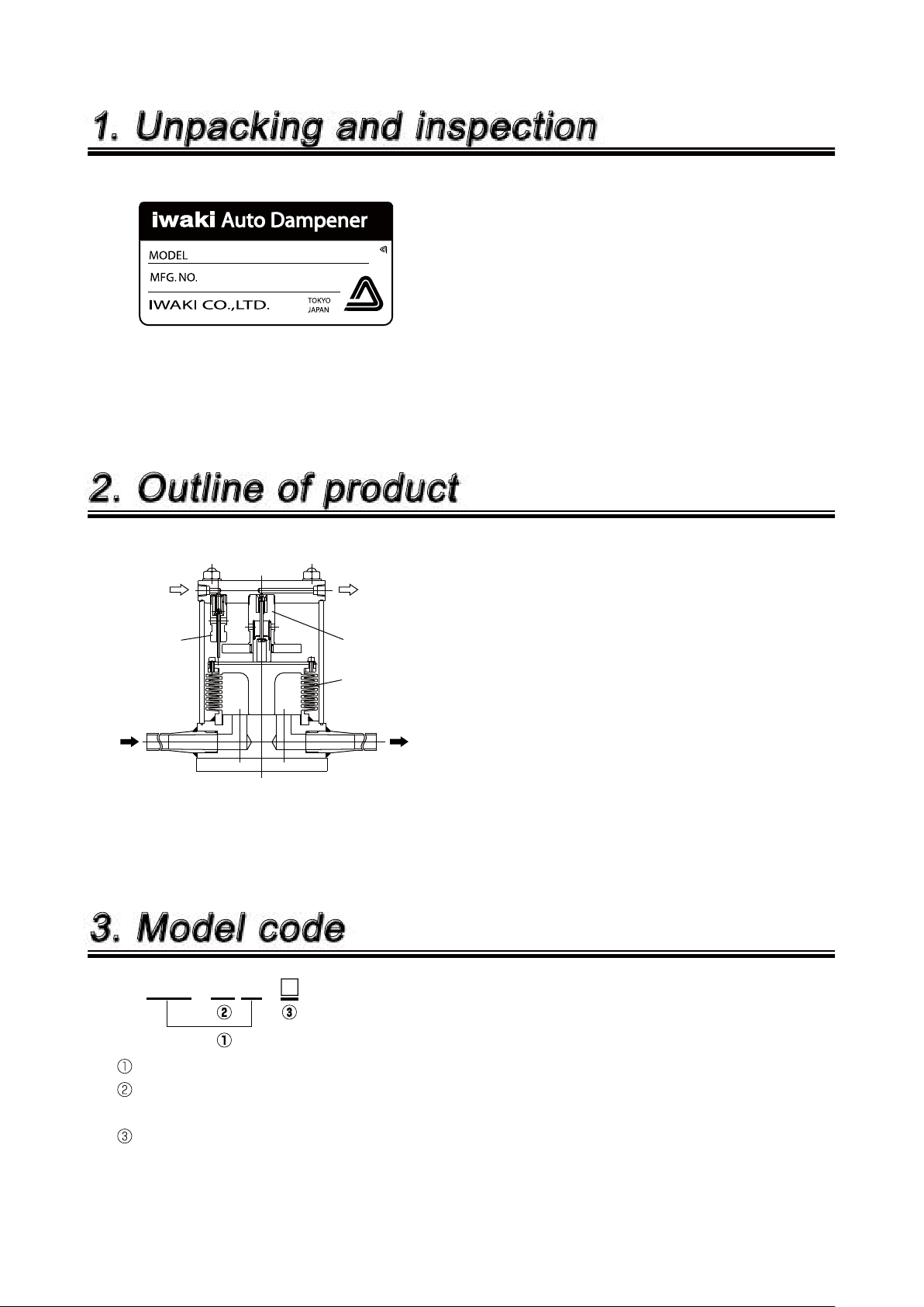
Inlet
Pressure
adjusting valve
Pressure
adjusting valve
Air supply
Bellows
Outlet
Air exhaust
1. Unpacking and inspection
After unpacking the product, check the following
points to ascertain that the product is exactly your
ordered one.
(1) if the model code on the nameplate is the same as
your order.
(2) if the product is not broken or bolts and nuts are not
loosened during transportation.
2. Outline of product
IWAKI auto-dampener the PDA-W series are
exclusively designed for the pneumatic driven bel-
lows pump to dampen the liquid pulsation.
The liquid discharged from the pump is transferred
to outlet through bellows. At this moment, the sup-
ply air is automatically adjusted by the pressure
regulating valve and this functions to dampen the
liquid pulsation.
3. Model code
PDA - 20 W -
Series code
Capacity (Max. discharge capacity of corresponding pump)
20 : 20 L/min. 40 : 40 L/min. 80 : 80 L/min.
Special version
No symbol : Standard version With symbol : Special version
-
-
5 -
5
-
Page 8

4. Specification
Model PDA-40W PDA-80W
Applied pump
Temp. ran g e (
Max. liquid press. (MPa)
Supply air press. (MPa)
Pulsation press width (Mpa)
Liquid pipe connection
Air piping connection
Wet end material
● Notes on operation
(1) Do not handle the liquid which is apt to be crystallized or contains solids.
Otherwise life of parts is shortened.
(2) Do not use the product exceeding the max. allowable liquid and air pressure.
Otherwise the pump or dampener may fail.
(3) If the AC-3 controller is used to drive the pump, use the solenoid valve of double solenoid and 2-position type. If
single solenoid type is used, good dampening effect can not be obtained.
Note: Performance and dimensions may be changed without prior notice.
)
10-100 101-150 151-180 10-10 0 101-150 151-180
0.5 0.5
0.2-0.5 0.15-0.3 0.15-0.2 0.2-0.5 0.15-0.3 0.15-0.2
PFA tube ø19 mm ø 16 mm PFA tube ø25 mm ø 22 mm
PDA-20W
FW-20, FS-30
0.3 0.2 0.5 0.3 0.2
Within 0.06 (in case liquid viscosity is within 1 - 50 mPa•s)
Rc 1/4 (Female)
PTFE, PFA
FW-40, FS-60 FW-80
10-80
0.2-0.5
-
-
6
-
6 -
Page 9

5. Dimension and mass
■
PDA-20, 40, 80W
PDA-20W
PDA-40W
PDA-80W
ABCD E FGHMass (kg)
348 148 215 191
388 188 255 229
408 208 323 266
ø
19 × ø16
ø
25 × ø22
ø
25 × ø22
18 33 135 7
23 36 162 12
25 38 188 17
-
7 -
-
7
-
Page 10

6. Structure and names of parts
■
PDA-20, 40, 80W
No Name Q'ty Material Remarks
Bellows unit 1 PTFE, PFA
1
Cylinder 1 A6063 Fluor coat
2
Plate 1 A5052 Fluor coat
3
OUT guide 1 SUS304
4
Slider 1 PPS
5
Stud bolt 4 SUS304 PTFE coat
6
Valve A 2 SUS304
7
Pin nut 1 SUS304
8
Pin 1 SUS304
9
Spring A 1 SUS304WPB
10
Spring B 2 SUS304WPB
11
Cover 1 A5052 Fluor coat
12
Spacer 1 PVC
13
IN guide 1 SUS304
14
Val ve seat 2 F K M
15
No Name Q'ty Material Remarks
Slider pin 1 SUS304
16
O-ring 2 FKM
17
Cap nut 4 SS Fluor coat
18
Plate washer 4 SS Fluor coat
19
O-ring 1 FKM S-10
20
Stopper 1 SUS304
21
Spacer A 1 PVC
22
Electrode holder 2 SUS304
23
O-ring 2 FKM P-3
24
Hex screw 2 SS
25
Bellows plate 1 SUS304
26
Bellows flange 2 SUS304
27
Hex bolt 6 SS
28
Spring washer 6 SS M4
29
*
M3
12
×
*
O-ring
PDA-20W
PDA-40W
PDA-80W
S-135
172
194. 5
×
3
×
2
-
8 -- 8 -
Page 11

7. Main parts and labelling
OUT label
Air exhaust port
Nameplate
shows model and MFG.No.
OUT label
Discharge port
Cover
Fix the cover at installation
IN label
Air supply port
IN label
Suction port
-
-
9 -
9
-
Page 12

Installation
1. B ef o r e u s e
2. Installation
3 Piping
-
10
..........................................................
-
.................................................
..................................................
11
11
12
Page 13

1. Before use
(1) Do not stop the supply air to the dampener while discharge piping is pressurized.
Otherwise the bellows may be deformed. Also, the pulsation reduction effect can not be received.
(2) Do not use the dampener at a higher pressure than the specified pressure of the pump.
The dampener may fail if it continuously operates exceeding the max. allowable liquid pressure and the max.
allowable supply air pressure. (Refer to 4. Specification)
(3) Do not handle the liquid which is apt to crystallize or contains slurry.
These liquids shorten the life of bellows.
(4) Pay attention to stripping agents or solvents.
• Some strippers may cause the cracks in a short time in the bellows or in piping (PFA material).
(Guarantee period is different for these liquids. Ask IWAKI.)
• Risk of fire. Do not connect the electrodes with any device including our controllers when using solvent.
WARNING
Do not connect the electrodes with any device including our controllers when using a solvent. Solvents may catch fire due to a electric spark.
(5) Surface temperature of the dampener
WARNING
The temperature of the dampener or pipe surfaces becomes very high while a high temperature liquid is pumped. Do not touch them with bare hands. Always wear protective
clothing.
Model
PDA-20W
PDA-40W
PDA-80W
Liquid temp. Room temp.
180 deg.C 74 deg.C 20 deg.C
180 deg.C 66 deg.C 20 deg.C
80 deg.C 20 deg.C
Cylinder surface temp.
40 deg.C
2. Installation
(1) Connect tubes to Inlet and outlet of the dampener horizontally.
(2) Install the dampener between the pump and the filter, as close to the pump. Keep the tube length
between the dampener and the pump less than 1 meter.
(3) Keep a space around the dampener for maintenance work.
(4) Mount the dampener and the pump securely on a flat foundation.
-
11 -
-
11
-
Page 14

Attached to tube
To pipe line
Attached to tube
To pipe line
Tube fitting
Tube fitting
3. Piping
Piping example
Discharge side
Pressure
gauge
(PG2)
Solenoid
Suction side
Pressure
reducing valve
Air supply source
(to seal air)
Pump
valve
Tak e i n
Dampener
IN OUT
Filter
Pressure
gauge
(PG2)
Exhaust
: Liguid piping
: Air piping
■
Liquid piping
(1) There is the distinction of suction and discharge
side tubes of dampener. Pay attention to the con-
nection. "I" is marked for suction side and "O"
for discharge side.
(2) Keep the pump and the dampener free of any
excessive load such as piping weight when tub-
ing each devise. Support tubing to protect the
dampener from tubing vibration.
(3) In case that high temperature liquid is handled,
piping must be done so that the dampener can
not be affected by the expansion and shrinkage
of the pipe because of the heat.
(4) Install the filter in the discharge piping.
(5) Employ the tube which has the pressure resist-
ance more than that of specified max. pressure of
the dampener.
(6) For mounting of pipe joints, pay attention so
that the air can not be sucked in. Especially, the
air sucked in suction piping causes unstable or
impossible discharge.
(7) PFA tubes are equipped for suction and dis-
charge ports. Tube diameters are:
PDA-20W : 19 × 16 mm
PDA-40W : 25 × 22 mm
PDA-80W : 25 × 22 mm
Use the tube fittings which correspond to tube
diameters(See the left draw.).
Note. Pipe line tubes should have larger bore
than the suction/discharge bore.
-
12
12 -
-
-
Page 15

■
Air piping
CAUTION
Use the instrument air which is dust free and dehumidified as supply air. If the supply
air contains foreign matters, water, or oil, the pressure adjusting valves may malfunction
and air may leak from the air exhaust port.
(1) Air piping should be connected to the dampener on the discharge tube beyond the pressure reducing
valve.
CAUTION
Pipe diameter must be the same as that of the pump (solenoid valve). If the pipe diameter to the dampener is small, necessary air can not be supplied to the dampener inlet
because of pressure down, which will bring reduction of dampening effect or deformation of the bellows.
CAUTION
Install a pressure reducing valve for each combination of the pump/dampener. If only a
pressure reducing valve control several combinations of pump/dampener, the pulsation
reduction effect will reduce or the bellows are deformed because of the pressure down
at dampener inlet.
(2) In case that air adjusting valve is installed
If the valve (marked with * on the illustration below) is installed in the air piping for adjusting a stroke
rate of the pump, install it not to interrupt the air supply to the dampener as shown on the illustration
below.
To pump (solenoid valve)
*
(Good)
*
Air supply source
Pressure reducing valve
(3) When the pressure reducing valve is installed for the pump and the damper separately.
The set pressure for the damper should be equal to the damper.
(No good)
To the auto-dampener
-
13 -
-
13
-
Page 16

OPERATION
1. Preparation for operation
2. Operation
3. Stopping
-
14
-
...................................................
.....................................................
........................
15
15
16
Page 17

1. Preparation for operation
When the pump is operated first time together with the dampener, check the followings.
(1) Check to see if no damage, loosened bolts or leakage are found on dampener (pump).
(2) Air pressure adjustment
This auto-dampener automatically adjusts the air pressure to be sealed depending on handled liquid pressure, which
requires no adjustment on the dampener.
2. Operation
Order Operation Check items
Start pump. Confirm if liquid is discharged normally.
1
Adjust pump discharge capacity and pressure.
2
Refer to Operating Instruction of pump for details of pump operation.
3
If no abnormality is found, start full operation.
4
Confirm by pressure gauge if air pressure does not
exceed specified pump pressure.
CAUTION
Right after the pump starts, the dampener exhausts air intermittently. This is because
the pressure adjusting valves function until load fluctuation is gone. Note that this is not
abnormal. Installing the muffler into the exhaust port, the exhaust noise can be reduced.
(Fitting bore: RC1/4)
CAUTION
Check that pneumatic pressure is applied to auto-dampener while pump operation. If
pneumatic pressure is not applied, pulsation dampening effect may be reduced or bellows
may be deformed.
In case the bellows of dampener is broken, it may happen the pumped liquid gets into
pneumatic piping. Take suitable protective measure in the system.
CAUTION
When the pump operates at 30 spm or below, the air is exhausted from the dampener in
sync with operation.
-
15 -
-
15
-
Page 18

CAUTION
Do not run the pump in time-lag operation. In the time-lag operation, the bellows of autodampener may fail in a short time. Also pulsation dampening effect can not be obtained.
When the auto-dampener is used, the time-lag should be zero.
Time-lag operation: When proximity switches detects the bellows movement and the
switching-over signal is transferred to the solenoid valve, the
switching-over signal is outputted with time lag. This is called "timelag operation". IWAKI controllers (AC-1, FD, SC and FDC) can not
operate the pump in time-lag operation. Pay attention to the timelag operation if the pump is operated by programmable controller or
so.
3. Stopping
(1) Stop the pump according to the procedure mentioned in operating instructions of the pump and controller. The air
is eliminated from the dampener after stoppage.
(2) Add the supply air to the auto-dampener while pump is stopped.
CAUTION
If air supply is interrupted when discharge piping is pressurized, the bellows may be
deformed. Be sure to release the residual pressure.
(3) Before the pump is stopped for a long time, confirm that pressure is released from the dampener and then stop the
air supply.
-
16
-
Page 19

Maintenance
1. Troubleshooting
2. Maintenance & inspection
3. Consumable parts
-
17
-
........................................
....................................
......................
18
19
19
Page 20

1. Troubleshooting
Trouble
Large pulsation
(Beyond specified range)
Air is mixed in
the liquid.
Liquid leaks.
Air leaks
(Cylinder)
Air leaks
(Air exhausting
part)
Cause Countermeasure
● Too high discharge pres-
sure.
● Air pressure adjusting valve
at intake or exhaust side is
clogged.
● Wor n valve se at .
● Too low supply air pressure
to dampener.
● Broken bellows inside
dampener
● Broken bellows.
(Air is mixed in discharged
liquid.)
● Stud bolts are not tightened
enough.
● Deterioration or deforma-
tion of O-ring.
● Air pressure adjusting valve
at exhaust side is clogged.
○ Check filter and replace.
○ Disassemble and clean. (*)
○ Replace valve seat. (*)
○ Keep the supply air pressure
to dampener.
○ Replace bellows unit. (*)
○ Replace bellows unit. (*)
○ Tighten.
○ Replace O-ring(*)
○ Disassemble and clean. (*)
Inspection & check items
a. Filter blinding or drying
b. If filter is wetted enough.
a. Check air filter.
a. Refer to item Air Piping on
Installation section.
a. If specified air pressure is
added to dampener.
b. If the dampener is not used
beyond specified pressure
a. If specified air pressure is
added to dampener.
b. If the dampener is not used
beyond specified pressure.
c. If residual pressure is
released.
a. Refer to Periodic Inspec-
tion on Maintenance and
Inspection.
a. Check air filter.
Note: Items marked (*) are done by IWAKI.
-
18
-
Page 21

2. Maintenance & inspection
WARNING
● Wear protectors
When piping is removed or pump is disassembled/assembled, wear protective gear
such as safety goggles and protective gloves etc.
● Release pressure inside piping
If pressure is not released from piping, liquid may be splashed. Release residual pressure before maintenance works start.
● Interruption of supplied air
Interrupt air supply to dampener before maintenance works start.
● Power off
Always turn off power supply prior to maintenance works. Display a sign near power
supply switch to notify other person that someone is "WORKING".
Turned on, by mistake, power supply during maintenance works may lead to personal
injury. Each operator must pay special attention.
■
Routine inspection
a. Confirm if the liquid is discharged normally from dampener (pump).
b. Confirm the vibration width of pressure gauge to see no change in discharge capacity and pressure.
c. Confirm if pipe does not vibrate abnormally.
■
Periodical inspection (Make the inspection once a month or more.)
If the air leakage through cylinder part is confirmed, stop the pump after pump discharge side pressure is released
to leave it until it is cooled down. And then, securely tighten the cap nuts of dampener.
Tightening torque
PDA-20W PDA-40W
6.4 N m 6.4 N m 12.7 N m
PDA-80W
3. Consumable parts
Repair is done by IWAKI.
No. Q'ty/unit
11
Bellows unit
15 2Valve seat
Note1: The quantity shows the number of the parts which required to a dampener.
Note2: Time to be replaced is just for your reference. It is not guaranteed.
Note3: The durability of consumable parts depends on pressure, temperature and characteristics of liquid.
Time to be replacedParts
One year (Continuous operation)
-
19 -
Page 22

: IWAKI EUROPE GmbH
Germany
: IWAKI Italia S.R.L.
Italy
: IWAKI Nordic A/S
Denmark
: IWAKI Sverige AB
Sweden
: IWAKI Suomi Oy
Finland
: IWAKI Norge AS
Norway
: IWAKI France S.A.
France
: IWAKI PUMPS (UK) LTD.
U.K.
: IWAKI (Schweiz) AG
Switzerland
: IWAKI (Austria) GmbH
Austria
: IWAKI Holland B.V.
Holland
: IWAKI Iberica Pumps, S.A.
Spain
: IWAKI Belgium n.v.
Belgium
TEL : (49)2154 9254 0
TEL : (39)02 990 3931
TEL : (45)48 24 2345
TEL : (46)8 511 72900
TEL : (358)9 2742714
TEL : (47)66 81 16 60
TEL : (33)1 69 63 33 70
TEL : (44)1743 231363
TEL : (41)26 674 9300
TEL : (43)2236 33469
TEL : (31)297 241121
TEL : (34)943 630030
TEL : (32)1367 0200
FAX : 2154 1028
FAX : 02 990 42888
FAX : 48 24 2346
FAX : 8 511 72922
FAX : 9 2742715
FAX : 66 81 16 61
FAX : 1 64 49 92 73
FAX : 1743 366507
FAX : 26 674 9302
FAX : 2236 33469
FAX : 297 273902
FAX : 943 628799
FAX : 1367 2030
IWAKI CO.,LTD. 6-6 Kanda-Sudacho 2-chome Chiyoda-ku Tokyo 101-8558 Japan
U.S.A.
Australia
Singapore
Indonesia
Malaysia
Taiwan
Thailand
Hong Kong
China
China
China
China
Philippines
Korea
TEL:(81)3 3254 2935 FAX:3 3252 8892(http://www.iwakipumps.jp)
: IWAKI America Incorporated
: IWAKI Pumps Australia Pty. Ltd.
: IWAKI Singapore Pte. Ltd.
: IWAKI Singapore (Indonesia Branch)
: IWAKIm Sdn. Bhd.
: IWAKI Pumps Taiwan Co., Ltd.
: IWAKI (Thailand) Co.,Ltd.
: IWAKI Pumps Co., Ltd.
: IWAKI Pumps (Guandong) Co., Ltd.
: GFTZ IWAKI Engineering & Trading (Guangzhou)
: IWAKI Pumps Co., Ltd. (Beijing)
: IWAKI Pumps (Shanghai) Co., Ltd.
: IWAKI Chemical Pumps Philippines, Inc.
: IWAKI Korea Co.,Ltd.
TEL : (1)508 429 1440
TEL : (61)2 9899 2411
TEL : (65)6316 2028
TEL : (62)21 690 6606
TEL : (60)3 7803 8807
TEL : (886)2 8227 6900
TEL : (66)2 322 2471
TEL : (852)2 607 1168
TEL : (86)750 380 9018
TEL : (86)20 8435 0603
TEL : (86)10 6442 7713
TEL : (86)21 6272 7502
TEL : (63)2 888 0245
TEL : (82)2 3474 0523
FAX : 508 429 1386
FAX : 2 9899 2421
FAX : 6316 3221
FAX : 21 690 6612
FAX : 3 7803 4800
FAX : 2 8227 6818
FAX : 2 322 2477
FAX : 2 607 1000
FAX : 750 380 9078
FAX : 20 8435 9181
FAX : 10 6442 7712
FAX : 21 6272 6929
FAX : 2 843 3096
FAX : 2 3474 0221
T389-2 '06/11
 Loading...