

IWAKI Magnetic Drive Pump
MXM (Asia version: English
Instruction Manual
Read this manual before use of product
)

Thank you for selecting an Iwaki MXM Series Magnetic Drive Pump. This instruction manual
deals with "Safety instructions", "Outline", "Installation", "Operation", and "Maintenance"
sections. Please read through this manual carefully to ensure the optimum performance, safety
and service of your pump.
Contents
Important instructions ···································································· 1
Safety instructions ·········································································· 2
Outline 1. Unpacking & Inspection
2. Model codes
3. Operating conditions
4. Part names
Installation 1. Before installation
2. Pipework
3. Wiring
4. Protection equipment
Operation 1. Before operation
2. Operation
3. Shutdown
Maintenance 1. Troubleshooting
2. Maintenance & Inspection
.....................................................................
........................................................................
........................................................................
............................................................................
.............................................................
........................................................................
........................................................................
..............................................................
..................................................
........................................................
..........................................................
.....................................................
.............................................
5
6
7
8
14
15
17
18
20
21
22
24
26
3. Disassembly & Assembly
4. Spare & Wear parts
This instruction manual should be kept on hand by the end user for
quick reference.
Contact us or your nearest dealer if you have any questions.
...............................................
........................................................
29
36
Important instructions
For the Safe and
Correc t Handl ing of the Pump
●
"Safety Instr uct ion" section deals with important det ails about handling of the product. Before
use, read this section carefully for the prevention of personnel injury or property damage.
●
Observe the instructions accompanied with "WAR NI NG" or "CAUTION" in this manual. These
instructions are very important for protecting users from dangerous situations.
●
Th e symb ol s o n t his in stru c t io n m anu a l h ave the fol lowi ng m e an i n g s:
Nonobservance or misapplication of “Warning”
WARNING
sections could lead to serious accident which may
result in death.
Nonobservance or misapplication of “Caution” sec-
CAUTION
tions could lead to personal injury or property damage.
Types of Symbols
Indicates that “Warning” or “Caution” must be exercised. Inside this triangle, a concrete and practical i mage provided as a war ni ng or caution message is depicted.
Indicates a prohibited action or procedure. Inside or near this circle, a concrete and
practical image of the activity to be avoided is depicted.
Indicates a n i mp or t a nt ac tion or pro ced u re wh ich must be pe r forme d or ca rried out
without fail. Failure to follow the instructions herein can lead to malfu nction or
damage to the pump.
For exportation
Technology related to the use of goods in this instruction manual falls in the category of
technology contained in the Foreign Exchange Order Attachment, which includes com-
plementary export control of technology. Please be reminded that export license, which
is issued by the Ministry of Economy, Trade, and Industry could be required, when this is
exported or provided to someone even in Japan.
- 1 -
Safety instruction
WARNING
● Access limitation
The magnet drive pump has a pair of strong magnets (the magnet capsule
unit and drive magnet). The strong magnet field could adversely affect the
persons who are assisted by electronic devices such as the pacemaker.
● Power OFF
Be sure to turn off power before starting maintenance/repair work. Make
sure no one turns on power while working on the pump, otherwise it may
result in a serious accident. If your work field is noisy or dark, let other peo-
ple know about the situation by displaying a notice such as "POWER OFF
(Maintenance)" near a power switch.
● Wear protective clothing
Always wear protective clothing such as eye protection and protective
gloves during pipework or dismantlement of the pump.
● Lifting pump
When lifting the pump, apply a chain or belts to the eye bolts to keep the
pump horizontal.
Prohibited
Tur ning of f po we r
Wear protective
gear
● Do not remodel pump
Do not remodel the pump. We are not responsible for any personal injury or
property damage due to modification.
● When handling dangerous liquid
For the transfer of the harmful liquid as mentioned below, be sure to con-
duct daily inspection and maintenance for the prevention of liquid/gas leak-
age.
1. Explosive or flammable liquid
2. Corrosive chemicals
3. Harmful liquid or gas
● Keep good ventilation
Poisoning may result when handling a toxic or odorous liquid. Install an air
fan in order to reduce the possibility of health damage.
No Remodeling
- 2 -
Safety instruction
CAUTION
● Attention to magnetic force
Strong magnets are used in this pump. Personal injury may be caused
from the strong magnetic force. Follow the procedure on "Disassembly &
Assembly" when conducting maintenance work.
● Do not run pump dry
Running the pump without liquid, friction heat damages the inside of pump.
Dry running takes place when starting the pump with a closed suction line.
● A qualified operator only
The pump must be handled or operated by a qualified person with a full
understanding of the pump.
● Specified application only
The use of the pump in any application other than those clearly specified
may result in failure or damage.
● Take countermeasures against static electricity
When low electric conductivity liquids such as ultra-pure water and fluor
TM
inactive liquid (e.g. Fluorinert
ated in the pump and may cause static discharge.
● Conduct degassing before operation
Always prime the pump and remove air before operation. Note that hydro-
gen peroxide and sodium hypochlorite easily generate gas and degassing is
) are handled, static electricity may be gener-
Prohibited
Prohibited
needed before every operation. Otherwise, sliding parts may be damaged.
● Countermeasure against efflux
Take protective measures against an accidental chemical overflow results
from pump or piping breakage. Do not soak chemicals into the ground direc-
tory.
● Disposal of the used pump
Dispose of a used pump in accordance with local laws and regulations
(Consult a licensed industrial waste products disposing company.).
- 3 -

Outline
1. Unpacking & Inspection
2. Model codes
3. Operating conditions
4. Part names
- 4 -
.........................................
.............................
...........................................
........................
5
6
7
8
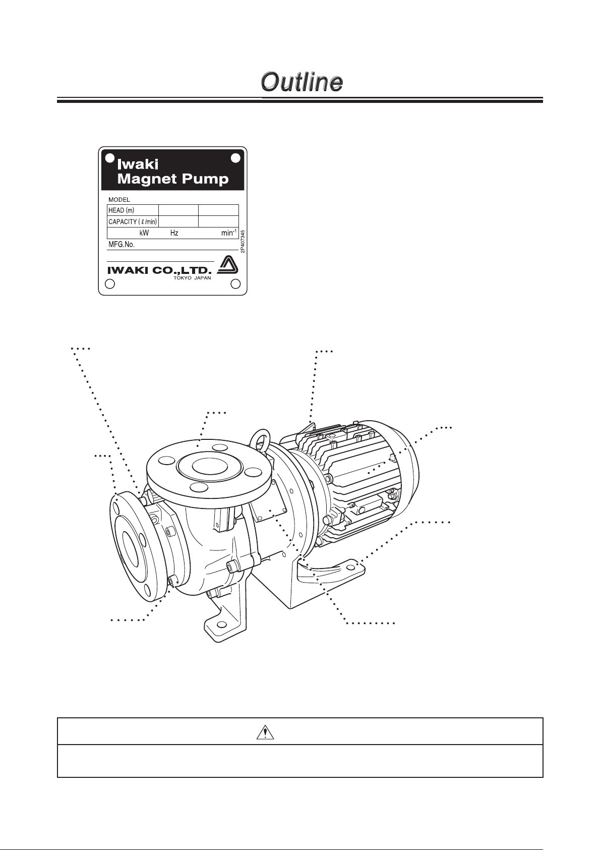
1. Unpacking & Inspection
Outline
On unpacking the product, check the following
points. If you find any problems, contact your
nearest distributor.
1. Check the information on nameplate (model
code, flow rate, discharge pressure and voltage)
to see if the product is delivered as per order.
2. Check for transit damage, deformation, and loose
bolts.
Pump unit
Not capable of self-priming. Prime the pump
via inlet or outlet before operation.
Inlet
Drain port
Do not flow chemicals directly
onto the ground. Always drain a
liquid into a suitable container.
Follow an applicable local regulation at disposal of liquid.
Motor nameplate
Observe the power voltage specified on the
nameplate.
( Follow an applicable local power regulation.)
Outlet
Motor (Drive unit)
The motor power is
transmitted to the
pump.
Foot
Be sure to fix the
pump.
Pump label
Observe the specification on the pump label.
CAUTION
Do not wipe labels or the pump body with a solvent.
- 5 -

Outline
2. Model codes
MXM 54 3 - 150 3 E CF V J - B
a b c d e f g h i
a. Pump bore
Inlet bore × Outlet bore
22: 25A × 25A
44: 40A × 40A
54: 50A × 40A
b. Motor output
0: 0.4kW 1: 0.75kW 2: 1.5kW 3: 2.2kW 5: 3.7kW
c. Impeller diameter
70-150mm
d. Impeller code
1 or 2 ········· MXM22
1 or 2 ········· MXM44
1, 2, 3, 4 ···· MXM54
e. Wet end material
E: CFRETFE
f. Bearing/spindle material
CF: High density carbon/High purity alumina ceramic
FF: High purity alumina ceramic/High purity alumina ceramic
KK: SiC/SiC
g. O ring material
V: FKM E: EPDM A: AFLAS
h. Flange connection/Motor standard
J : JIS flange + JIS motor
I : ISO flange + IEC motor
A : ANSI flange + JIS motor
®
P: DAI-EL PERFLUOR
®
i. Special specification
Blank: Standard B: With base H: High-temperature version S: Special specification
- 6 -
Outline
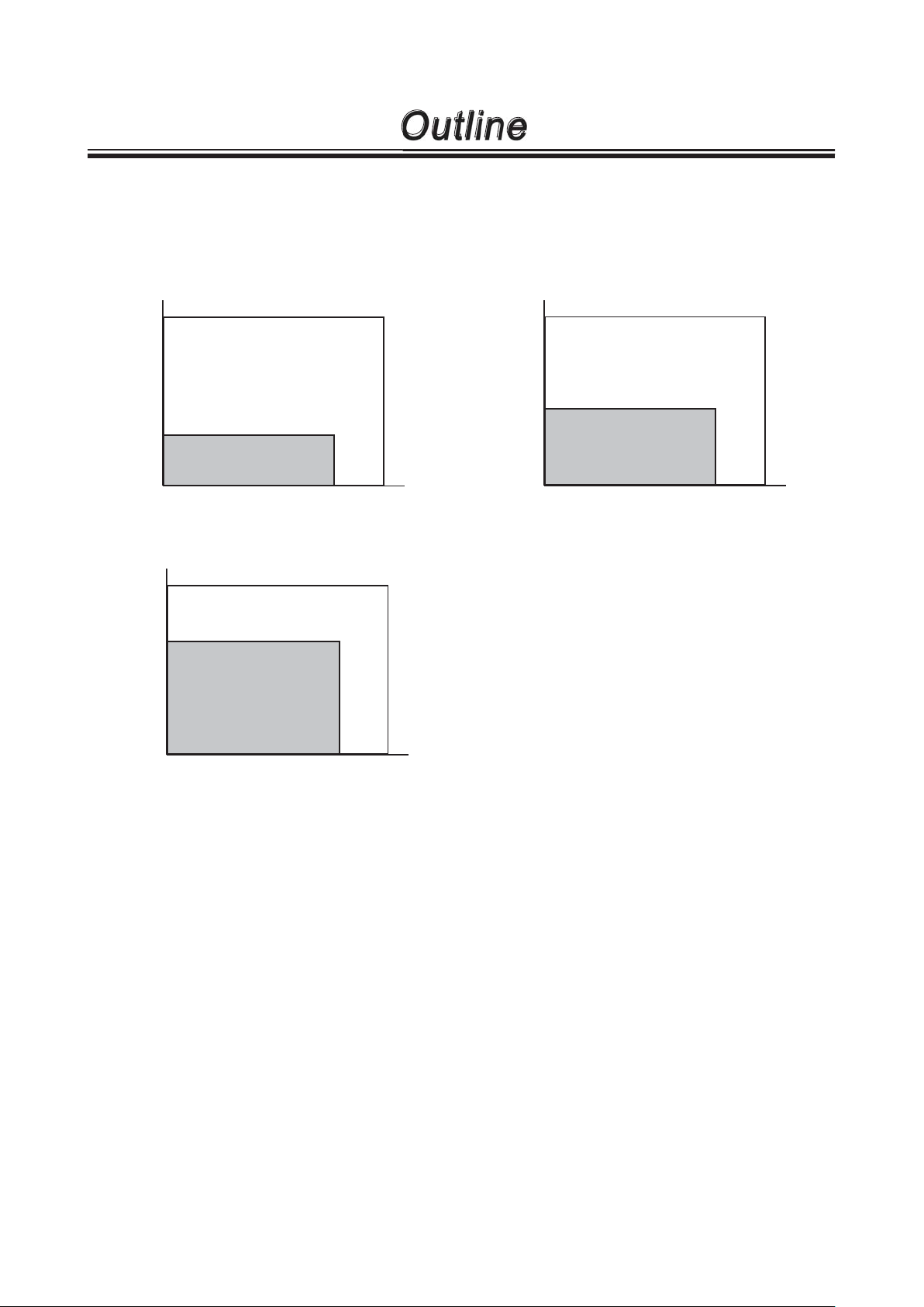
3. Operating conditions
Maximum operating pressure
Observe the maximum operating pressure below.
MXM220/221 MXM441/442
0.7
0.7
High temperature type (H)
0.2
Max. operating pressure (MPa)
-10 90 100
MXM542/543/545
0.7
High temperature type (H)
0.45
Max. operating pressure (MPa)
-10 90 100
Temp.
(°C)
Temp.
(°C)
High temperature type (H)
0.3
Temp.
Max. operating pressure (MPa)
-10 90 100
Ambient temperature: 0-40°C
Relative humidity: 35-85%RH
(°C)
NOTE: The minimum liquid temperature for
AFLAS® O ring is 10°C.
Slurry
Generally the pump can not send slurry except the KK type (SiC bearing and SiC spindle).
The KK type can handle slurry up to 5% (concentration), 50μm (particle size) and 80Hs (hardness).
Contact us for details.
Performance change
Shaft power, discharge capacity and pump head vary with specific gravity and viscosity. The pump is
designed for a specified liquid. Contact us before changing liquid specification.
Temperature change
Note that viscosity, vapour pressure or corrosiveness changes with liquid temperature. The change is
shown in performance such as flow rate while the pump itself is not affected.
The maximum liquid viscosity for the FF type
1 mPa•S (cP) or more
- 7 -
Outline
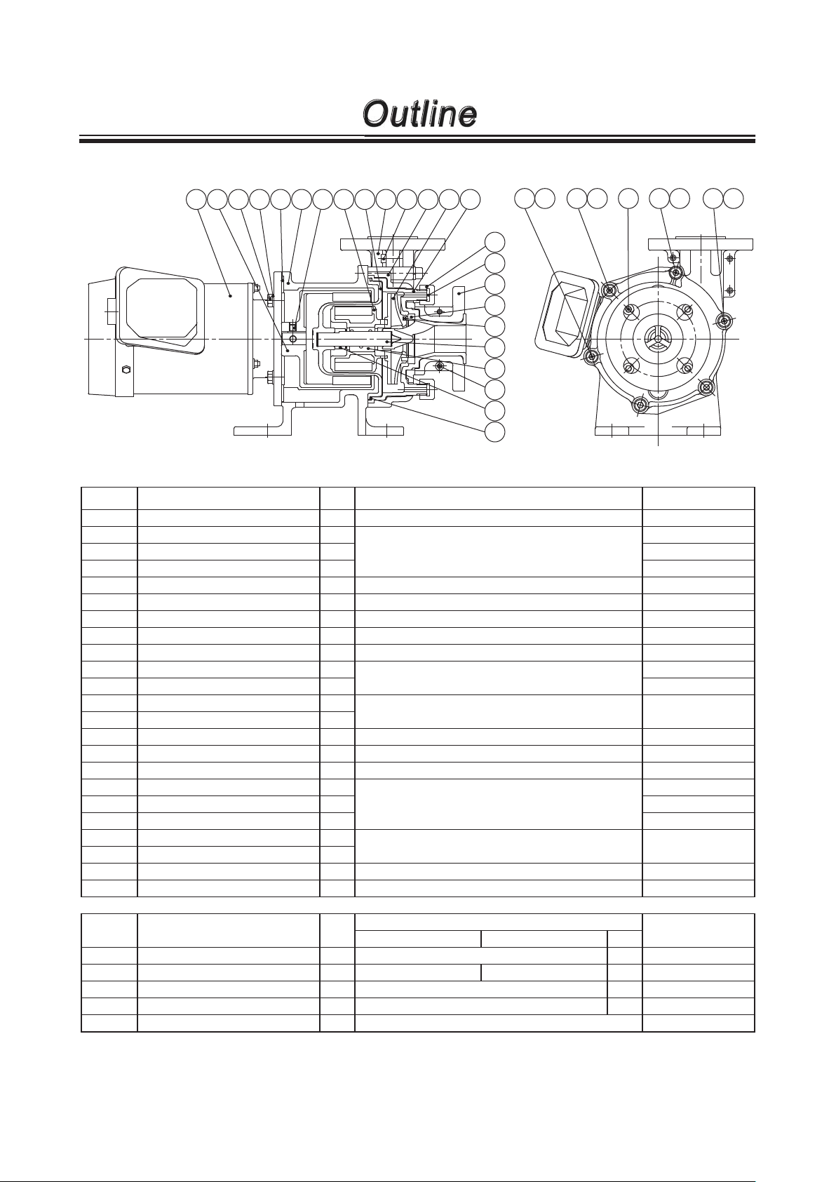
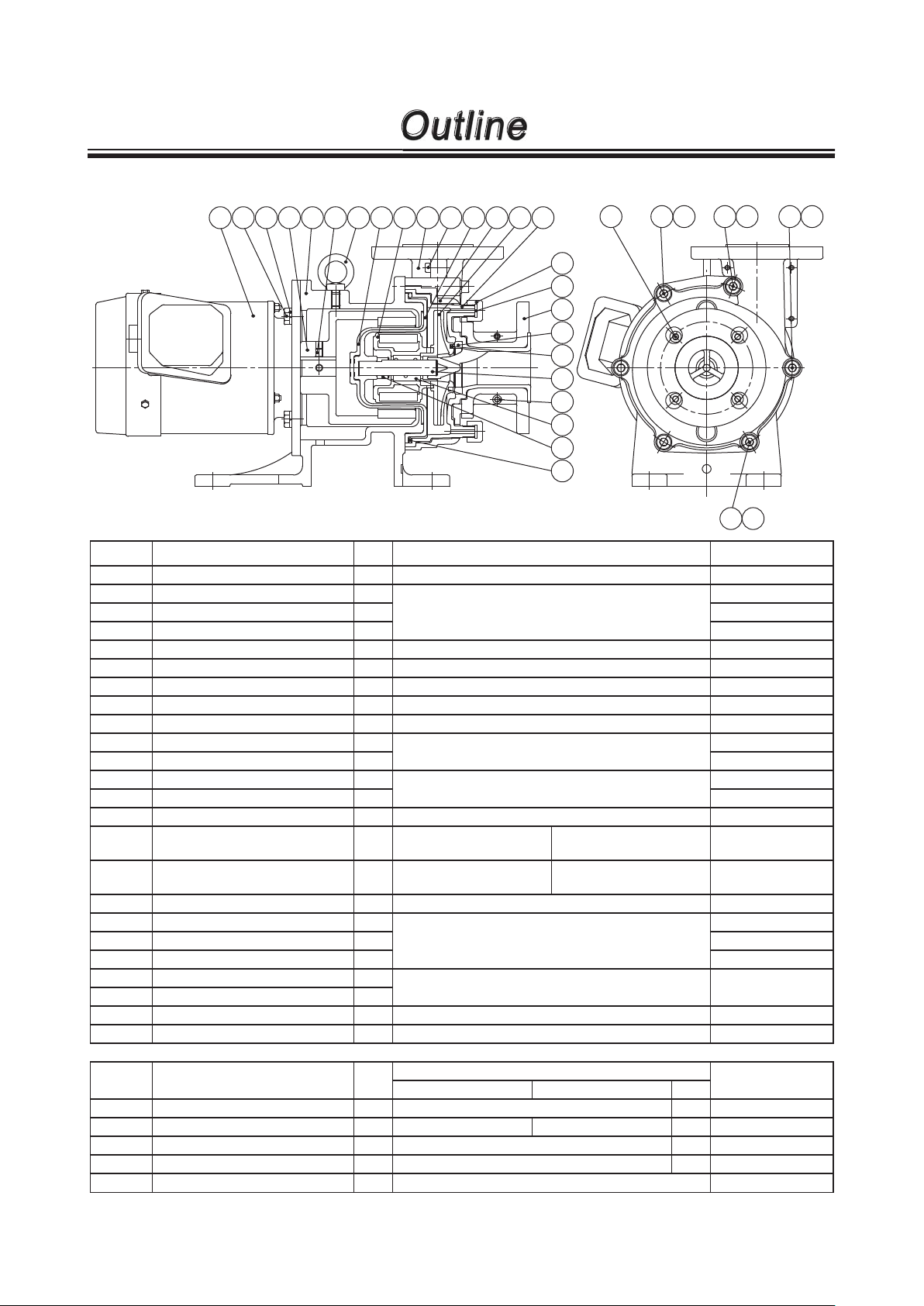
4. Part names
801 858 901.1 554.2 330.1 330 908.1 859 158 100.3 903.3 100.2
230
100.1
903.1 554.1 903.1 554.1 903.1903.5 554.1
122.1
400.2
100.4
314.1
314.2
210
310
903.4
314.3
400.1
MXM220
NO. PART NAMES Q'TY MATERIAL REMARKS
100.1 FRONT CASING 1 CFRETFE
100.2 COVER A 1
DUCTILE IRON100.3 COVER B 1
100.4 COVER C 2
122.1 DRAIN CAP 2 ETFE
158 REAR CASING 1 CFRETFE
230 IMPELLER 1 CFRETFE
330 FRAME 1 DUCTILE IRON
330.1 MOTOR SPACER 1 SPCC
400.1 O RING 1
400.2 GASKET 2
554.1 SPRING WASHER 6
554.2 SPRING WASHER 4
V: FKM E: EPDM A: AFLAS
P: DAI-EL PERFLUOR
STNLS STL M8
®
®
JIS B 2401 G140
801 MOTOR 1 0.4kW
858 DRIVE MAGNET UNIT 1 0.4kW: FERRITE MAGNET+ALUMINIUM ALLOY
859 MAGNET CAPSULE 1 0.4kW: FERRITE MAGNET+CFRETFE
901.1 HEX. HEAD BOLT 4
903.1 HEX SOCKET HEAD BOLT 3 M8×50
STNLS STL
M8×25
903.2 HEX SOCKET HEAD BOLT 3 M8×70
903.3 HEX SOCKET HEAD BOLT 3
903.4 HEX SOCKET HEAD BOLT 2
STEEL M6×18
903.5 HEX SOCKET HEAD BOLT 4 STNLS STL M8×15
908.1 HEX SOCKET SET SCREW 2 STEEL
903.2
554.1
NO. PART NAMES Q'TY
CF FF KK
MATERIAL
210 SPINDLE 1 HIGH PURITY ALUMINA CERAMIC SiC
310 BEA RING 1
HIGH DENSITY CARBON
HIGH PURIT Y ALUMINA C ERAMIC
SiC
314.1 LINER RING 1 HIGH PURITY ALUMINA CERAMIC SiC
314.2 MOUTH RING 1 FILLED PTFE SiC
314.3 REAR THRUST 1 CFRETFE
- 8 -
REMARKS

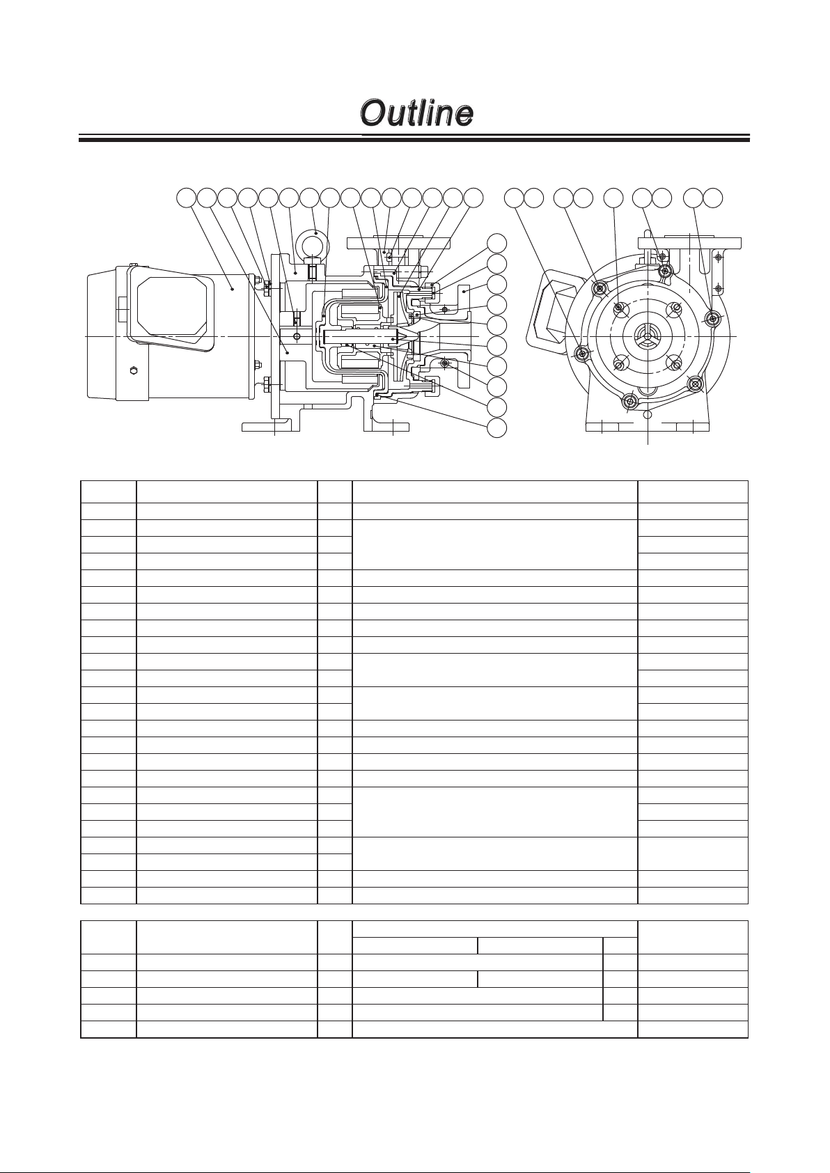
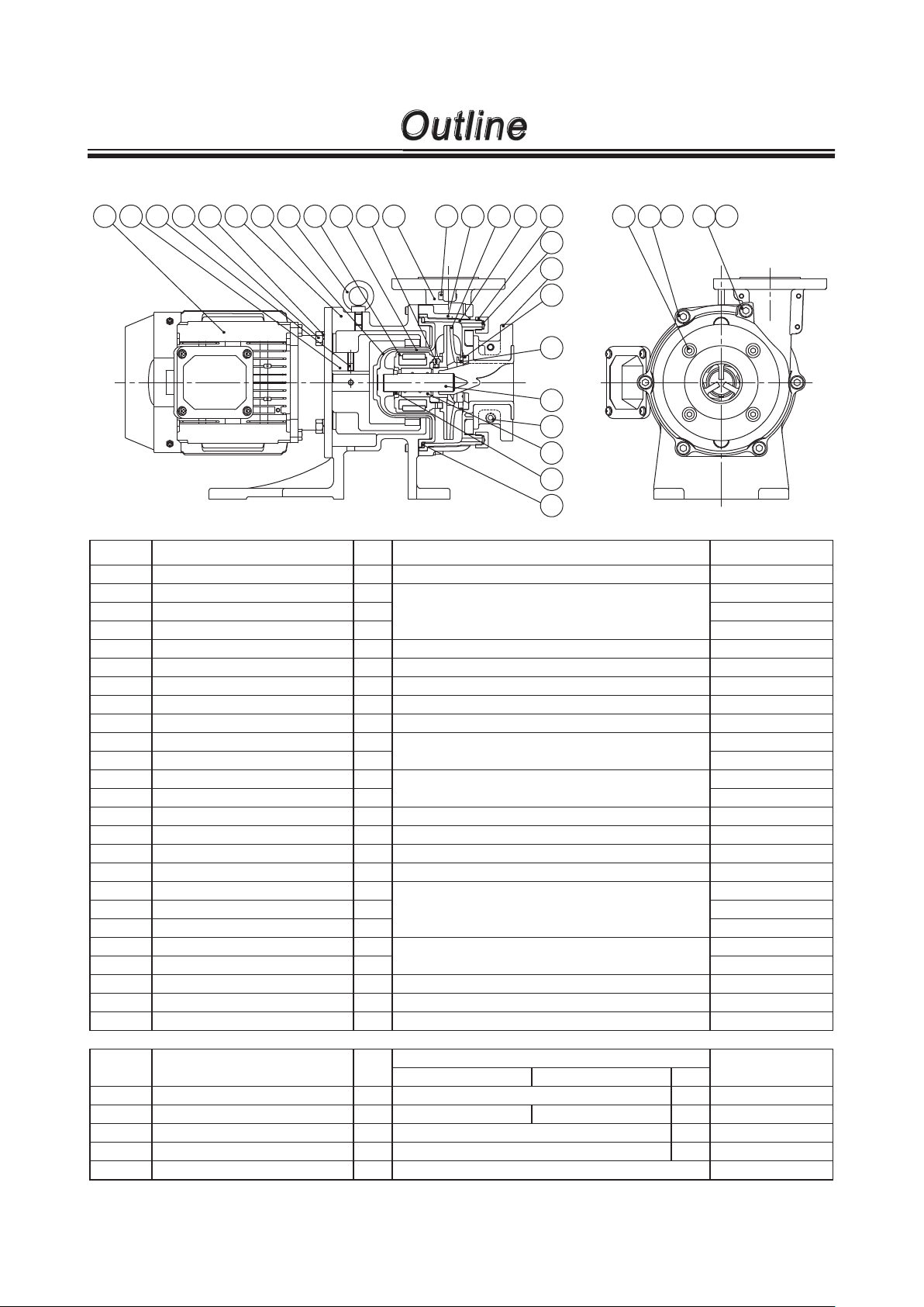
Outline
MXM220H
801 858 901.1 554.2 908.1 330.2 330 554.4 901.3 900 159 859 158
100.3
903.3 100.2 230 100.1
122.1
400.2
100.4
314.1
314.2
210
310
903.4
314.3
400.1
903.1 554.1903.1 554.1 903.1903.5 554.1
903.2
NO. PART NAMES Q'TY MATERIAL REMARKS
100.1 FRONT CASING 1 CFRETFE
100.2 COVER A 1
DUCTILE IRON100.3 COVER B 1
100.4 COVER C 2
122.1 DRAIN CAP 2 ETFE
158 REAR CASING 1 CFRETFE
159 REAR CASING COVER 1 FRP
230 IMPELLER 1 CFRETFE
330 FRAME 1
330.2 MOTOR ADAPTER 1
400.1 O RING 1
400.2 GASKET 2
DUCTILE IRON
V: FKM E: EPDM A: AFLAS
P: DAI-EL PERFLUOR
®
®
JIS B 2401 G140
554.1 SPRING WASHER 6
STNLS STL M8554.2 SPRING WASHER 4
554.4 SPRING WASHER 4
801 MOTOR 1 0.4kW
858 DRIVE MAGNET UNIT 1 FERRITE MAGNET+DUCTILE IRON
859 MAGNET CAPSULE 1 FERRITE MAGNET+CFRETFE
900 EYE BOLT 1 STEEL M10
901.1 HEX. HEAD BOLT 4
901.3 HEX. HEAD BOLT 4 M8×25
903.1 HEX SOCKET HEAD BOLT 3 M8×50
STNLS STL
M8×20
903.2 HEX SOCKET HEAD BOLT 3 M8×70
903.3 HEX SOCKET HEAD BOLT 3
903.4 HEX SOCKET HEAD BOLT 2
STEEL M6×18
903.5 HEX SOCKET HEAD BOLT 4 STNLS STL M8×15
908.1 HEX SOCKET SET SCREW 2 STEEL
554.1
NO. PART NAMES Q'TY
CF FF KK
MATERIAL
210 SPINDLE 1 HIGH PURITY ALUMINA CERAMIC SiC
310 BEA RING 1
HIGH DENSITY CARBON
HIGH PURIT Y ALUMINA C ERAMIC
SiC
314.1 LINER RING 1 HIGH PURITY ALUMINA CERAMIC SiC
314.2 MOUTH RING 1 FILLED PTFE SiC
314.3 REAR THRUST 1 CFRETFE
- 9 -
REMARKS
Outline
MXM221/ 221H
801 858 901.1 554.2 908.1 330 900 159 859 158 100.3 903.3 100.2
230
100.1
122.1
400.2
100.4
314.1
314.2
210
310
903.4
314.3
400.1
903.1 554.1903.1 554.1 903.1903.5 554.1
903.2
NO. PART NAMES Q'TY MATERIAL REMARKS
100.1 FRONT CASING 1 CFRETFE
100.2 COVER A 1
DUCTILE IRON100.3 COVER B 1
100.4 COVER C 2
122.1 DRAIN CAP 2 ETFE
158 REAR CASING 1 CFRETFE
159 REAR CASING COVER 1 FRP
High-temp type only
230 IMPELLER 1 CFRETFE
330 FRAME 1 DUCTILE IRON
400.1 O RING 1
400.2 GASKET 2
554.1 SPRING WASHER 6
554.2 SPRING WASHER 4 M10
V: FKM E: EPDM A: AFLAS
P: DAI-EL PERFLUOR
STNLS STL
®
®
JIS B 2401 G140
M8
801 MOTOR 1 0.75kW
858 DRIVE MAGNET UNIT 1 FERRITE MAGNET+DUCTILE IRON
859 MAGNET CAPSULE 1 FERRITE MAGNET+CFRETFE
900 EYE BOLT 1 STEEL
901.1 HEX. HEAD BOLT 4
903.1 HEX SOCKET HEAD BOLT 3 M8×50
STNLS STL
M10×25
903.2 HEX SOCKET HEAD BOLT 3 M8×70
903.3 HEX SOCKET HEAD BOLT 3
903.4 HEX SOCKET HEAD BOLT 2
STEEL M6×18
903.5 HEX SOCKET HEAD BOLT 4 STNLS STL M8×15
908.1 HEX SOCKET SET SCREW 2 STEEL
554.1
NO. PART NAMES Q'TY
CF FF KK
MATERIAL
210 SPINDLE 1 HIGH PURITY ALUMINA CERAMIC SiC
310 BEA RING 1
HIGH DENSITY CARBON
HIGH PURIT Y ALUMINA C ERAMIC
SiC
314.1 LINER RING 1 HIGH PURITY ALUMINA CERAMIC SiC
314.2 MOUTH RING 1 FILLED PTFE SiC
314.3 REAR THRUST 1 CFRETFE
- 10 -
REMARKS
Outline
MXM441/ 441H/ 442/ 442H
801 901.1 554.2 858 330 908.1 900 159 859 100.3 903.3 158 100.2
230
100.1
122.1
400.2
100.4
314.1
314.2
210
903.4
310
314.3
400.1
903.1 554.1903.5
903.2
903.2
554.1
554.1
903.2
NO. PART NAMES Q'TY MATERIAL REMARKS
100.1 FRONT CASING 1 CFRETFE
100.2 COVER A 1
DUCTILE IRON100.3 COVER B 1
100.4 COVER C 2
122.1 DRAIN CAP 2 ETFE
158 REAR CASING 1 CFRETFE
159 REAR CASING COVER 1 FRP
High-temp type only
230 IMPELLER 1 CFRETFE
330 FRAME 1 DUCTILE IRON
400.1 O RING 1
400.2 GASKET 2
554.1 SPRING WASHER 6
554.2 SPRING WASHER 4 M10
V: FKM E: EPDM A: AFLAS
P: DAI-EL PERFLUOR
STNLS STL
®
®
JIS B 2401 G160
M10
801 MOTOR 1 0.75/1.5kW
858 DRIVE MAGNET UNIT 1
859 MAGNET CAPSULE 1
0.75kW FERRITE
MAGNET+DUCTILE IRON
0.75kW FERRITE
MAGNET+CFRETFE
1.5kW REAR EARTH
MAGNET+DUCTILE IRON
1.5kW REAR EARTH
MAGNET+CFRETFE
900 EYE BOLT 1 STEEL
901.1 HEX. HEAD BOLT 4
903.1 HEX SOCKET HEAD BOLT 3 M10×55
STNLS STL
M10×25
903.2 HEX SOCKET HEAD BOLT 3 M10×75
903.3 HEX SOCKET HEAD BOLT 3
903.4 HEX SOCKET HEAD BOLT 2
STEEL M6×18
903.5 HEX SOCKET HEAD BOLT 4 STNLS STL M8×20
908.1 HEX SOCKET SET SCREW 2 STEEL
554.1
NO. PART NAMES Q'TY
CF FF KK
MATERIAL
210 SPINDLE 1 HIGH PURITY ALUMINA CERAMIC SiC
310 BEA RING 1
HIGH DENSITY CARBON
HIGH PURITY ALUMINA CERAMIC
SiC
314.1 LINER RING 1 HIGH PURITY ALUMINA CERAMIC SiC
314.2 MOUTH RING 1 FILLED PTFE SiC
314.3 REAR THRUST 1 CFRETFE
- 11 -
REMARKS
Outline
MXM542/ 543/ 545
159
900801 858 908.1 901.1 554.2 330
859 158
942
100.3 903.3 100.2
230
100.1 122.1
400.2
100.4
314.1
314.2
210
903.4
310
314.3
400.1
903.1 554.1903.2903.5 554.1
NO. PART NAMES Q'TY MATERIAL REMARKS
100.1 FRONT CASING 1 CFRETFE
100.2 COVER A 1
DUCTILE IRON100.3 COVER B 1
100.4 COVER C 2
122.1 DRAIN CAP 2 ETFE
158 REAR CASING 1 CFRETFE
159 REAR CASING COVER 1 FRP
High-temp type only
230 IMPELLER 1 CFRETFE
330 FRAME 1 DUCTILE IRON
400.1 O RING 1
400.2 GASKET 2
554.1 SPRING WASHER 6
554.2 SPRING WASHER 4
V: FKM E: EPDM A: AFLAS
P: DAI-EL PERFLUOR
STNLS STL
®
®
JIS B 2401 G165
M10
1.5/2.2kW: M10 3.7kW: M12
801 MOTOR 1 1.5/2.2/3.7kW
858 DRIVE MAGNET UNIT 1 REAR EARTH MAGNET+DUCTILE IRON
859 MAGNET CAPSULE 1 REAR EARTH MAGNET+CFRETFE
900 EYE BOLT 1 STEEL M10
901.1 HEX. HEAD BOLT 4
903.1 HEX SOCKET HEAD BOLT 5 M10×40
STNLS STL
1.5/2.2kW: M10×30 3. 7kW: M1 2×35
903.2 HEX SOCKET HEAD BOLT 1 M10×80
903.3 HEX SOCKET HEAD BOLT 3
903.4 HEX SOCKET HEAD BOLT 2 M8×20
STEEL
M6×18
903.5 HEX SOCKET HEAD BOLT 4 STNLS STL M8×15
908.1 HEX SOCKET SET SCREW 1 STEEL M8×10
942 LOCK PIN 2 CFRETFE
NO. PART NAMES Q'TY
CF FF KK
MATERIAL
210 SPINDLE 1 HIGH PURITY ALUMINA CERAMIC SiC
310 BEA RING 1
HIGH DENSITY CARBON
HIGH PURITY ALUMINA CERAMIC
SiC
314.1 LINER RING 1 HIGH PURITY ALUMINA CERAMIC SiC
314.2 MOUTH RING 1 FILLED PTFE SiC
314.3 REAR THRUST 1 CFRETFE
- 12 -
REMARKS

Installation
1. Before installation
2. Pipework
3. Wiring
4. Protection equipment
- 13 -
.............................................
.................................................
...............................
..........................
14
15
17
18

1. Before installation
Installation
1. Discharge line
2. Gate valve
3. Check valve
4. Pressure gauge
5. Motor
6. Magnetic drive pump
Within 1m
Piping layout
7. Expansion joint
8.
Vacuum (compound) gauge
9. Straight suction line
10. Suction line
11. Air vent line
12. Pipe support
■ Installation location
1. Select a flat and sound foundation where is free from vibration
2. Keep a work space wide enough for motor removal (back pull out), assembly or dismantlement.
3. The foundation should be larger than a pump base footprint.
■ Pump position
1. Install the pump as close to a supply tank and under flooded suction appl ication.
2. In the suction lift application, arrange the auxiliary line for priming and mount a foot valve at the suction
pipe end.
■ Foundation work
1. See the diagram and instructions below as necessary.
2. For the pump without the base plate, do not mount the foot in the foundation. Otherwise, the pump can
not be dismantled.
Foundation bolt
Baseplate
Concrete foundation
- 14 -
Liner

Installation
2. Pipework
■
Tightening torque between the pump and pipework
Connect the pump to pipework via inlet and outlet flanges according to the tightening torque below. Tighten
bolts diagonally at even tension.
Model Bolt size Tightening torque
MXM22/44/54 M16 79N•m
NOTE1: The table is based on use of metal pipe flanges with rubber gaskets.
NOTE2: Select the best bolt length so as not to come in contact with the pump.
■
Piping load and momentum
Try not to apply heavy load to the pump inlet and outlet flanges. Permissible piping weight and moment to
the pump are as below.
Y
Z
Y
Z
X
X
Permissible stress to inlet & outlet flanges
Load direction
Discharge flange Suction flange
Fx 0.71 0.89
Fy (compression/tension) 0.89/0.44 0.58
Fz 0.58 0.71
Load kN
Permissible moments to inlet & outlet flanges
Load direction
Discharge flange Suction flange
Mx 0.35 0.46
My 0.46 0.35
Mz 0.23 0.23
Moment kN•m
- 15 -

Installation
■
Suction line
1. Flooded suction application
Always realize the flooded suction.
2. Suction line bore
A suction line bore should be equal to or larger than pump inlet.
3. Shortest line length
Keep the shortest length with the minimum number of bends.
4. Straight line length
A suction line should be laid on straight at least for 500mm from the pump inlet.
For easy pump removal and maintenance, install a removable pipe of 300mm in the straight line.
5. Air pocket
Do not make any projection or arched line where air may be trapped.
A suction line should be laid with a rising gradient of 1/100 toward the pump.
6. Use of the eccentric reducer
If the pump inlet bore is different from that of suction pipe, use the eccentric reducer. Upper side should
always be level. Air may be trapped if it is mounted upside down.
7. Gate valve installation
In flooded suction application, always install a gate valve on a suction line for overhaul & inspection.
8. Flushing line
Lay on a flushing line for cleaning the pump when handling a harmful liquid.
9. Suction line end
The suction line end should always be at least 500mm lower than a liquid level for the prevention of
entrained air.
10. In suction lift application
• The distance between the end of a suction line and the bottom of a supply tank should be 1 to 1.5 times
wider than the suction line bore.
• Be sure to install a foot valve or a check valve on a suction line.
11. Piping support
Use metal supports so that the pump is not subject to piping weight or thermal stress.
12. Connections
Each connection must be completely sealed so that air can not be entrained. Otherwise, a poor flow or
the seizure of bushing may result.
- 16 -

Installation
■
Discharge line
1. Discharge line bore
When a discharge line is long but its bore is equal to the pump outlet bore, the specified performance
may not be obtained because pipe resistance becomes high. Calculate pipe resistance in advance to
decide a discharge line bore.
2. Gate valve installation
Install a gate valve on a discharge line to adjust flow rate and protect the motor from overload. Install
check valve as necessary, the optimum installation order is : Pump → Check valve → Gate valve.
3. Discharge valve installation
A discharge valve should be positioned about 1m away from the pump. An air vent line should be mount-
ed near the valve in order to prevent air from remaining.
4. Pressure gauge
Install a pressure gauge on a discharge line to check a discharge capacity and delivery head.
5. Check valve
Install a check valve in the following cases.
• Discharge line is longer than 15m.
• A delivery head is higher than 15m.
• The distance between a liquid level in a supply tank and the top end of a discharge line is 9m or longer.
• Two pumps run in parallel.
6. Air vent line
Lay on an air vent line on a discharge line when the horizontal line length is longer than 15m or more.
7. Drain
Install a drain valve as necessary (to prevent liquid from freezing in the pump, etc.).
8. Piping support
Use metal supports so that the pump is not subject to piping weight or thermal stress.
9. Priming line
Lay on a priming line on a discharge line in suction lift application.
3. Wiring
Electrical works or wiring must be carried out by a qualified person according to local laws or regulations.
• Use the electromagnetic switch which conforms to the motor specifications of voltage and capacity etc.
• When installing the pump out of doors, take a measure to prevent rain water from getting into the switch.
• Install the electromagnetic or the push-button switch apart from the pump.
*See the instruction manual of the motor manufacturer for the motor detail.
- 17 -

Installation
4. Protection equipment
It is recommended to install the following monitoring devices in order to protect the pump.
1. Current sensor/ Power sensor The sensors monitor the motor load and stop the pump on the detection
of load change, giving an alarm.
2. Pressure sensor The sensor monitors the starting pressure and stops the pump on the
detection of pressure change, giving an alarm.
3. Flow sensor The sensor monitors the discharge flow and stops the pump on the
detection of flow change, giving an alarm.
4. Level sensor The sensor monitors the liquid level in the tank and stops the pump
when it falls below the specified level, giving an alarm.
It is recommended to install two or more monitoring devices. The more monitoring devices, the more pos-
sibility of protecting the pump.
The DR series dry running protector (electric current sensing type) is also available as an option. Contact us
for detail.
- 18 -

OPERATION
1. Before operation
2. Operation
3. Shutdown
- 19 -
............................................
............................................
.................................
20
21
22

Operation
1. Before operation
CAUTION
● Never run pump dry or shut off a suction valve during operation. Otherwise,
the pump fails in a short period. Especially for the FF types, the bearing and
spindle can be damaged in a quite-short time of about one minute.
● Check the rotational direction of the pump. Clockwise seen from the motor
end is a correct direction. Operation in the reverse direction may cause
pump damage.
● Stop the pump within one minute if cavitation occurs. Do not continue operation with entrained air. Especially for the FF types, the bearing and spindle
can be damaged in a quite-short time of about one minute.
● Stop the pump immediately when the magnet coupling is disconnected. The magnetic
force reduces if the pump keeps on running for one minute or longer in this condition.
● Keep liquid temperature change within 80˚C through operation and stopping.
Retighten the drain cap when the surrounding or liquid temperature significantly changes. The maximum number of ON-OFF operation should be within six times an hour. Frequent ON-OFF operation can reduce the pump life.
Prohibit
● Start the pump with a closed discharge valve in order to avoid water hammer.
● Closed-discharge operation should be within one minute. If the pump runs
with a discharge valve closed for a long time, the liquid temperature inside
the pump rises and it damages the pump.
● If power is interrupted when the pump is running, switch off and close a discharge valve.
● Take extra care so that the discharge pressure does not exceed the pump
limit. See page 7 for the maximum operating pressure.
● Risk of burning. Pump and pipe surface temperature rise high along with
liquid temperature. Do not touch the pump or pipe surface directly in or right
after operation.
Model Liquid temperatuer
MXM220/221
MXM441/442
MXM542/543/545
90°C 65°C
100°C 75°C
90°C 65°C
100°C 75°C
90°C 70°C
100°C 80°C
Possible highest surface temperature (at ambent 40°C)
● The noise level is shown below. In case the pump noise affects human
health or communication to secure a safety, provide a noise reduction cover.
Model Noise level
MXM220/221
MXM542/543/545
80dBMXM441/442
Caution
Caution
- 20 -

Operation
2. Operation
1. Fully close a discharge valve and fully open a suction valve.
2. Prime the pump.
• If the pump is in the flooded suction application, fully open both discharge and suction valves.
• If the pump is in the suction lift application, prime a suction line as well as the pump.
3. Check rotating direction of the motor.
• Close a discharge valve. Power the motor for a quick moment (within a second) in order to check the
rotation direction. A correct direction is shown with an "arrow" mark on the pump (Clockwise seen from
motor fan side).
• Check if the motor fan smoothly stops when turning off power.
NOTE: If the motor does not stop smoothly, check rotating parts.
4. Air elimination
• Before full-scale operation, eliminate the air in the pump.
• Fully open an air vent line. Run the pump for one second and repeat it 3 to 5 times for air elimination.
• After the air elimination, fully close a discharge valve.
NOTE: In case air vent line is not equipped, repeat the momentary run several times with a
discharge valve open.
5. Full-scale operation
• Start the pump with a discharge valve fully closed.
NOTE: Stop the closed-discharge operation within one minute.
• Check that discharge pressure rises to the shut off pressure.
• Gradually open discharge valve to obtain the specified pressure (capacity).
NOTE: Pay attention to the over-load caused by an excessively opened valve.
Precautions on operation
1. When the pump keeps running in negative rotation, the pump breaks.
2. Closed-discharge operation should be stopped within one minute.
3. Observe the minimum flow rate. Otherwise, friction heat may build up and damage the bearing and
sliding parts.
MXM220/221/441/442 MXM542/543/545
Impeller code Min flow rate Impeller code Min flow rate
1, 2 10L/m
*See page 6 "2. Model codes".
1, 2, 3 20L/m
450L/m
- 21 -

Operation
3. Shutdown
1. Slowly close a discharge valve.
Quick closing by a solenoid valve may cause water hammer and damage the pump. Be sure to slowly
close any discharge valve.
2. Switch off and stop the pump.
Check that the pump stops smoothly. If the pump stops roughly, make an inspection.
NOTE: When leave the pump stopped for a long period...
Take a countermeasure against freezing in the pump and piping or...
In case a blackout has interrupted operation, switch off the pump and close a
discharge line.
- 22 -

Maintenance
1. Troubleshooting ..................................24
2. Maintenance & Inspection...................26
3. Disassembly & Assembly....................29
4. Spare & Wear parts ............................36
- 23 -

Maintenance
1. Troubleshooting
Turn off power to stop operation upon sensing abnormalities. And then look for a root cause or
contact us as necessary.
Troubles
Liquid can not
be discharged.
Discharge
capacity is too
low.
Symptom
When a discharge
valve is closed.
The pump can not
be primed.
After starting, the
pressure drops as
a discharge valve
is opened.
The pressure
gauge keeps showing a low pressure.
Pressure & vacuum are normal.
Pressure is low
and vacuum is
very low.
When a discharge
valve is opened.
The readings of
pressure/vacuum
gauges drop to
zero.
The readings of
pressure/vacuum
gauges fluctuate
and drops to zero.
Vacuum is high.
Vacuum is very
high.
The readings of
pressure gauge
& vacuum gauge
fluctuate.
Vacuum is high but
pressure is normal.
Vacuum is normal
but pressure is
high.
Both pressure and
vacuum are low.
Cause
• Priming liquid level is
too low.
• Dry running
• The foot valve malfunction due to foreign matter clogging.
• Air ingress through a
suction line or a connection.
• Disconnection of the
magnet coupling
• Low pump speed
• The pump rotates in
reverse.
• The strainer is clogged
with foreign matters.
• Air pocket in suction
line
• Foreign matters are
clogged at impeller
inlet.
• Air ingress from a suction line or a connection.
• The pump or discharge
line clogs with foreign
matters.
• Resistance such as air
pocket in suction line.
• Actual delivery head is
too high or pipe resistance is too large.
• The motor rotates in
reverse.
Point to be checked
&
Countermeasures
• Stop and prime the
pump and resume
operation.
• Dismantle and inspect
the pump.
• Clean the foot valve.
• Check if suction line
connections are completely sealed.
• Check if liquid level in
supply tank is not too
low.
• Check if the motor
is not overloaded by
checking amperage.
• Check if foreign matters do not lock the
impeller or magnet
capsule.
• Check if voltage is normal.
• Check wiring or motor.
• Interchange motor wiring.
• Remove foreign matters.
• Check and correct suction line.
• Remove foreign matters.
• Check suction line connections and retighten
as necessary.
• Remove foreign matters or scales.
• Check if there is no
arched pipework.
• Check actual delivery
head and pipe resistance.
• Interchange motor wiring.
- 24 -

Maintenance
Troubles
The motor is
overheated.
A flow rate
has dropped
suddenly.
The pump
vibrates.
Symptom
When a discharge
valve is closed.
When a discharge
valve is opened.
• Voltage has dropped
greatly.
• Overload
• Surrounding temperature is too high.
Vacuum is high. • A suction line clogs
with foreign matters.
• The base is not
anchored firmly.
• Anchor bolts are loose.
• Cavitation occurs.
• Pump bearing is worn
or failed.
• Magnet capsule or
impeller is broken.
• Dynamic balance of
drive magnet is upset.
• Motor bearing is worn.
Cause
Point to be checked
&
Countermeasures
• Check voltage or frequency.
• Check specific gravity
and viscosity of liquid.
• Keep a good ventilation.
• Remove foreign matters.
• Fix the base.
• Retighten the bolts.
• Remove the cause of
cavitation.
• Replace as necessary.
• Replace as necessary.
• Investigate problems
and replace as necessary.
• Replace bearing or a
motor unit.
- 25 -

Maintenance
2. Maintenance & Inspection
WARNING
● Access limitation
The magnet drive pump has a pair of strong magnets. The strong magnet field could
adversely affect the persons who are assisted by electronic devices such as the pacemaker.
● Do not catch the finger
The magnetic force of the pump is powerful. Take care not to catch the finger in the
bracket.
● Wear protective clothing
Coming in contact with a harmful chemical liquid may cause eye or skin trouble. Wear
protective clothing such as a protective mask, goggles, gloves during work.
● Turn off power during maintenance work
Risk of electrical shock. Make sure a power source is turned off, and the pump and
devices are stopped prior to work.
■ Daily inspection
1. Always check for leakage before pump operation. Do not run the pump when liquid leaks. Check if the
drain cap is tight. Retighten as necessary.
2. Check whether the pump runs without abnormal noise or vibration.
3. Check a liquid level in a supply tank and a suction pressure.
4. Check that discharge capacity and a motor current value are as per specifications on the nameplate during operation.
NOTE A discharge pressure is in proportion to the specific gravity of liquid. The cock of
the pressure gauge or vacuum gauge should be opened only when measurement is
carried out. Close it right after measurement. If the cock remains open during pump
operation, the meter mechanism may be adversely affected by the abnormal pressure rise caused by water hammer action.
5. If a spare pump is stored, run it from time to time to keep it ready for operation at any time when needed.
6. Check discharge pressure, discharge capacity, and motor power supply voltage to see if they do not fluctuate during operation. See page 24 "1. Troubleshooting" as necessary.
- 26 -

Maintenance
■
Periodic inspection
To ensure efficient and smooth operation, perform periodic inspection. Be careful not to damage internal
sliding parts and plastic parts when dismantling the pump.
The magnetic force of the drive magnet unit and magnet capsule assembly is strong. Be careful not to
catch the finger. Do not put electrical devices such as a watch and mag card close to the magnets.
Interval
Every six months
(Maintain an
inspection record)
Part names
(Drive magnet unit)
Drive magnet
Hex. socket set screw
Rear casing
Rear thrust
(Magnet capsule
assembly)
Magnet capsule
Bearing
(Impeller unit)
Impeller
Mouth ring
Inspection items
● Wear trace
● If the drive magnet is correctly
mounted by hex. socket set
screws and they are not loose.
● Decentering of magnet and
motor shaft (Max.1/10mm)
● Wear tracks on an inner surface
● Cracks
● Rear thrust wear degree
● Spindle end wear degree
● Contamination in rear casing
● Wear tracks on the rear end or
side face of the magnet capsule
● Cracks on the rear end or side
face of the magnet capsule
● Bearing wear degree
● Loose fit of the impeller unit
● Mouth ring wear degree
● Cracks
● Evidence of cavitation (Wear or
seizing on the mouth ring.)
● Contamination in the impeller
● Impeller deformation
Measures
○ Finding wear trace, contact us.
○ Reset the drive magnet to the
motor shaft and retighten the
screws.
○ Retighten the hex. socket set
screws or replace the drive
magnet (Contact us).
○ Contact us.
○ Replace as necessary.
○ Contact us.
○ Replace as necessary.
○ Remove contamination.
○ Contact us.
○ Contact us.
○ Replace as necessary.
○ Replace or contact us.
○ Replace as necessary.
○ Replace as necessary.
○ Remove the cause of cavita-
tion.
○ Remove contamination.
○ Replace as necessary.
Front case
Rear case
Liner ring
Spindle
Drain cap
● Contamination
● Cracks
● Wear degree, cracks and wear
tracks on liner ring
● Drain port clogging
● Swelling or a crack on O ring
● Wear tracks on an unlikely portion
● Cracks
● Wear degree
● Loose fit
- 27 -
○ Remove contamination.
○ Replace as necessary.
○ Contact us.
○ Remove clogging
○ Replace as necessary.
○ Contact us.
○ Replace as necessary.
○ Replace as necessary.
○ Retighten the cap.

Maintenance
■
Wear limits of bearing and spindle
* If the clearance between the inner diameter of the bearing and the outer diameter of the spindle exceeds 1
mm, either the bearing or spindle, whichever has greater wear, should be replaced regardless of the wear
limit. For the ceramic bearing (FF) type, replace the bearing and spindle at the same time.
* Sliding parts may suffer initial wear in an initial operation phase. Note that this is not abnormal.
Model
Inner diameter of bearing
Outer diameter of spindle
See page 33 for baring replacement.
See page 31 for spindle replacement.
■
Wear limit of mouth ring
The mouth ring is 2 mm forward from the impeller when shipped. Before the step has reduced to 0 mm,
replace the mouth ring with new one.
Model MXM220/ 221/ 441/ 442/ 542/ 543/ 545
Before use
Wear limit
MXM220/ 221/ 441/ 442 MXM542/ 543/ 545
Before use Wear limit Before use Wear limit
18mm 19mm 24mm 25mm
18mm 17mm 24mm 23mm
7. 5m m
5.5mm
Before use
Mouth ring
2mm
Impeller
Mouth ring replacement
1. Heat the lugs on the mouth ring by a plastic
welder or industrial dryer and open the lugs up to
remove the mouth ring.
2. Heat the lugs on the mouth ring by a plastic
welder or industrial dryer and then close the lugs
down.
- 28 -

Maintenance
3. Disassembly & Assembly
WARNING
● Access limitation
The magnet drive pump has a pair of strong magnets. The strong magnet field could
adversely affect the persons who are assisted by electronic devices such as the pacemaker.
● Do not catch the finger
The magnetic force of the pump is powerful. Take care not to catch the finger in the
bracket.
● Wear protective clothing
Coming in contact with a harmful chemical liquid may cause eye or skin trouble. Wear
protective clothing such as a protective mask, goggles, gloves during work.
● Turn off power during maintenance work
Risk of electrical shock. Make sure a power source is turned off, and the pump and
devices are stopped prior to work.
CAUTION
●
Pay attention to magnetic force
The magnetic force is powerful. Take care so that iron pieces and iron powder do not
stick to the magnet of pump.
●
The powerful magnetic force can break the data of the magnetic card, disc or so. Do
not have the magnetic product close to the magnet of pump.
- 29 -

Front casing
Drain cap
Maintenance
■
Dismantlement
1. Flush out chemical liquid from the pump by
a flushing line. Then remove the drain cap to
empty the pump.
Wear protective clothing such as goggles,
rubber gloves, etc. during maintenance.
Coming in contact with a harmful chemical liquid may cause eye or skin trouble.
WARNING
Bracket
Front casing
2. Remove hex. socket head bolts from the front
casing to remove it from a bracket. Try to pull
out the front casing straight from the bracket so
as no to damage the spindle in it. The spindle
may stay in the front casing after removal. In this
case, take care not to loose the rear thrust.
CAUTION
A strong impact may crack the front casing. Be careful not to hit it.
Front casing
- 30 -

Maintenance
Spindle
Impeller
Magnet capsule
Rear casing
3. Pull out the impeller unit + the magnet capsule
assembly. Be careful not to scratch each part.
Note that the magnetic force of the magnet capsule assembly is strong. Keep it free from metal
pieces or powder. Do not scratch any sliding or
sealing surfaces.
CAUTION
The magnetic force of the magnet capsule assembly is powerful. Be careful not
to catch the finger in the impeller unit and
the assembly.
4. Insert a flat-head screwdriver between the rear
casing and the motor bracket. And then pull the
rear casing forward while lifting it slightly up.
If the spindle stays on the front casing, remove it
from the front casing. Fit the spindle to the rear
casing with the rear thrust mated at the end.
Always check the rear thrust is mated to the spindle before fitting spindle.
If the spindle can not be removed, warm a spindle connection with hot water (about 90°C) for
5 minutes and try again. Be careful not to be
scalded.
- 31 -
CAUTION
Be careful not to damage the sealing surface between the front casing and rear
casing where crushes the O ring.

Maintenance
5. Detach the impeller unit from the magnet capsule assembly as necessary. Be careful not to
damage the units.
a. MXM220/ 221/ 441/ 442
Slightly tap the back of impeller unit by plastics
hammer while holding the magnet capsule
assembly. If it is hard to remove, warm them in
hot water (about 90°C) for 5 minutes.
Take care not to burn yourself.
b. MXM542/ 543 /545
The impeller unit can not be separated from
the magnet capsule assembly unless the
lock pins are removed. Do not have an strong
impact to the impeller unit before removing the
pins.
Lock pins
Impeller
Lock pin
Impeller & magnet capsule
Lock pin
Magnet capsule
Turn the lock pins 90 degrees anticlockwise
using a flathead screwdriver and then push
it off. If it is hard to push it off, slightly tap the
end of driver handle.
The lock pins can also be turned by using the
4mm hex. wrench from the inside of magnet
capsule assembly. In this case turn the wrench
clockwise. The lock pins will be damaged if it
is turned in reverse direction. After unscrewing
the pins, push it off from the outside by using
a bar.
- 32 -

Maintenance
After the lock pins are removed, detach the
impeller unit from the magnet capsule assem-
bly by slightly tapping the back of the impeller
unit with a plastic hammer. If the impeller
unit is hardly removed, warm it in hot water
(approx. 90°C) for 5 minutes and tap it slightly,
again. Be careful not to scald in hot water.
To remove the bearing from the magnet cap-
sule assembly, first separate the impeller unit
from the assembly. Then use a hand press
with plastic extruding bar to extrude the bear-
ing toward impeller connection side.
To insert the bearing into the magnet capsule,
reverse this procedure. If the bearing can not
be removed, warm the magnet capsule assem-
bly with hot water (about 90°C) for 5 minutes
and try again. Be careful not to be scalded.
The end of
press-fitting part
Check no clearance between the
bearing surface
and the pressfitting parts.
Through-hole
U-shape hole
Bearing
■
Assembly
1. Mount the impeller unit to the magnet capsule
assembly.
a. MXM220/ 221/ 441/ 442
Press and fit the impeller unit into the magnet
capsule assembly with the U-shape hole under
the through hole.
Check that the end of press-fitting parts has
came at a bearing surface. If the impeller
unit can not be fitted to the magnet capsule
assembly, warm it in hot water (about 90°C for
5 minutes) for softening. Be careful not to get
scalded with hot water.
- 33 -

Maintenance
Lock pin
U-shape hole
ø3mm hole
b. MXM542/ 543/ 545
Attach the impeller unit to the magnet capsule
assembly.
The mating surface on the assembly has two
holes. The large hole (Stepped holes with 6mm
at outer dia. & 12mm at inner dia) is for the
lock pins and the small hole (3mm dia.) is for
cooling. Press the impeller unit into the magnet
capsule assembly with U-shape hole under the
smaller hole (3 mm dia.). If it is difficult to insert
them, warm the magnet capsule assembly in
the hot water (approx. 90°C) for 5 minutes. Be
careful not to scald at this time.
After fitting the impeller unit, push the lock pins
into the lock pin holes from the inside as far as
it will go.
Lock pin
Impeller
Magnet capsule
Lock pin
Use a flat-head screwdriver to turn the pins 90
degrees clockwise from the outside while hold-
ing the pins from the inside. Once it clicks, the
impeller unit is secured.
If the screw groove is deformed and can not be
used, the pin can be turned from the inside with
a 4mm hex. wrench. In this case pay attention
to turn the wrench anticlockwise. The lock pin
may be broken if it is turned in reverse.
- 34 -

Spacer
Maintenance
2. Insert the magnet c apsule assembly plus the
impeller unit into the rear casing slowly.
Do not allow iron pieces to adhere to the magnet
capsule assembly.
3. Mount the rear casing to the bracket with the
magnet capsule assembly in it.
Impeller
Bracket
CAUTION
Magnet force is very powerful. Apply plastic or wooden spacers between the rear
casing and the frame so as not to catch
the fingers.
4. Fit O ring to the front casing. Check that seal-
ing surfaces are free of dust or scratches. Make
sure that O ring is in place and will not be out of
the groove.
CAUTION
Replace O ring and gasket with new ones
at each time of replacement. Reusing old
O ring and gasket could reduce seal performance and result in leakage.
5. Mount the front casing to the motor bracket.
Tighten the hex. socket bolts diagonally and
equally. Tightening torque is shown below.
Model Tightening torque Bolt size
MXM220/221 12.5N•m M8
MXM441/442/542/543/545 24.5N•m M10
CAUTION
The hex. socket bolt length differs with
each position. Be sure to select proper
bolts to each position. Otherwise, leak or
other failure may result.
6. Hand tighten the drain cap and check it is
secured. Use a tightening tool such as pliers to
give it further torque, especially before operation
with a high-temperature or a high-pressure liquid. Be careful not to tighten it too much, or the
plastic cap may break.
- 35 -

Maintenance
4. Spare & Wear parts
Appropriate spare parts are necessary for a long period of continuous operation. We recommend
that wear parts be always in stock. Place an order for spares with the following information.
1. Part names and part number (See the diagram below.)
2. Pump model identification code and manufacturing number (See pump nameplate.)
3. Drawing number if you have our approval drawing
No. Part names Materials
High purity alumina ceramic
210 Spindle
310 Bearing
210
310
314.2 Mouth ring
314.3 Rear thrust
859
310
859
310
210
400.1 O ring
400.2 Gasket
Bearing,
+
Spindle set
Magnet cap-
+
sule assembly
Magnet cap-
+
sule assem-
bly, spindle
+
set
CF
KK SiC MXM0175 MXM0002
CF High density carbon MXM0183 MXM0016
KK SiC MXM0185 MXM0017
High purity alumina
FF
ceramic
CF/FF
Filled PTFE MXM204 MXM0063
KK SiC MXM205 MXM0064
MXM22/44: CFRETFE
MXM54: CFRPFA
CFRETFE +
CF
High density carbon
KK CFRETFE + SiC
CFRETFE +
FF
Highly purity alumina
ceramic
FKM MXM0218 MXM0305 MXM0006
EPDM MXM0220 MXM0306 MXM0007
AFLAS
DAI-EL PERFLUOR
FKM MXM0009
EPDM MXM0010
AFLAS
DAI-EL PERFLUOR
®
®
Selection codes
MXM220 MXM221 MXM441 MXM442
MXM0174 MXM0001
MXM0364 MXM0370
MXM0176 MXM0003
MXM0177
MXM0181
MXM0358
MXM0221 MXM0307 MXM0008
®
MXM0217 MXM0308 MXM0014
®
MXM0178
MXM0182
MXM0359
MXM0267 MXM0004 MXM0012
MXM0269 MXM0005 MXM0013
MXM0360 MXM0366 MXM0367
MXM0011
MXM0015
MXM542/543
MXM545
- 36 -

Maintenance
MXM22
903.4
100.4
Disabled single
with 903.4×2
554.1
903.1
122.1
122.1
Disabled single
100.2+100.3
With 903.3×3
400.2
400.2
903.2
554.1
903.5
903.4
100.1
903.3
903.3
314.2
230
903.3
310
330
(890)
859
900
210
901.2
554.3
314.3
901.3
400.1
858
554.4
908.1
220 only
330.1
908.1
158
220H only
330.2
159
554.2
901.1
MXM44
903.4
100.4
Disabled single
with 903.4×2
122.1
554.1
903.1
400.2
400.2
122.1
Disabled single
100.2+100.3
with 903.3×3
903.2
554.1
903.5
903.4
100.1
903.3
903.3
314.2
230
903.3
(890)
330
310
859
900
210
901.2
554.3
314.3
400.1
908.1
858
908.1
554.2
159
158
901.1
- 37 -

Maintenance
MXM54
903.4
903.2
554.1
122.1
122.1
400.2
400.2
903.1
554.1
Disabled single
100.2+100.3
With 903.3×3
903.5
903.4
100.1
903.3
942
314.2
903.3
903.3
230
330
942
310
900
859
314.3
210
210
KK type with hole
908.1
858
400.1
901.2
554.3
158
159
901.1
554.2
908.1
(890)
100.4
Disabled single
with 903.4×2
- 38 -

Maintenance
- 39 -

- 40 -

- 41 -

Aust ra lia IWAKI Pumps Australia Pty. Ltd.
Austria IWAKI (Austria) GmbH
Belgium IWAKI Belgium n.v.
China IWAKI Pumps (Shanghai) Co., Ltd.
Ch ina IWAKI Pumps (Guandong) Co., Ltd.
China
China
GFTZ I WAKI Engine ering & Trading (Gu angzhou)
GFTZ I WAKI Enginee ring & Trading (Be ijing)
Denmark IWAKI Nordic A/S
Finland IWAKI Suomi Oy
France I WAKI France S.A .
Germany IWAKI EUROPE GmbH
Holland IWAKI EUROPE NL Branch
Hong Kong IWA KI P ump s Co . , L td.
Indonesia
IWAKI Singapore (Indonesia Branch)
IWAKI CO.,LTD. 6-6 Kanda-Sudacho 2-chom e Chiyoda -ku Tokyo 101-8558 Japan
TEL : (61)2 9899 2411 FAX : 2 989 9 2421
TEL : (43)2236 33469 FAX : 2236 33469
TEL : (32)1367 0200 FAX : 1367 2030
TEL : (86)21 627 2 7502 FAX : 21 627 2 6929
TEL : (86)750 38 66228 FA X : 750 3866278
TEL : (86)20 8 435 0603 FAX : 20 8 435 9181
TEL : (86)10 64 42 7713 FAX : 10 64 42 7712
TEL : (45)4 8 24 2345 FA X : 48 24 2346
TEL : (358)9 2 745810 FA X : 9 2742715
TEL : (33)1 69 63 33 70 FAX : 1 6 4 49 92 73
TEL : (49)2154 925 4 0 FAX : 2154 92 54 48
TEL : (31)547 293 160 FAX : 547 292 3 32
TEL : (852)2 6 07 1168 FAX : 2 6 07 1000
TEL : (62)21 69 0 6606 FAX : 21 69 0 6612
TEL:(81)3 3254 2935 FAX:3 3252 8892(http://w ww.iwakipumps.jp)
Italy IWAKI Italia S.R.L.
Korea IWAKI Korea Co.,Ltd.
Malaysia IWAKIm Sdn. Bhd.
Norway IWAKI Norge AS
Singapore IWAKI Singapore Pte. Ltd.
Spain IWAKI Iberica Pumps, S.A.
Sweden IWAKI Sverige AB
Switzerland I WAK I (S chw eiz ) A G
Taiwan IWAKI Pumps Taiwan Co., Ltd.
Tai wan
IWAKI Pumps Taiwan (Hsin-chu) Co., Ltd. TE L : (886)3 573 5797 FAX : (8 86)3 573 5798
Thailand IWAKI (Thailand) Co.,Ltd.
U.K. IWAKI Pumps (UK) LTD.
U.S.A. IWAKI AMERICA Inc.
Vietnam IWAKI pumps Vietnam Co.,Ltd.
TEL : (39)02 9 90 3931 FAX : 02 99 0 42888
TEL : (82)2 263 0 4800 FAX : 2 263 0 4801
TEL : (60)3 78 03 8807 FAX : 3 7803 48 00
TEL : (47)66 81 16 60 FAX : 66 81 16 61
TEL : (65) 6316 2028 FA X : 6316 3221
TEL : (34)9 43 630030 FAX : 9 43 628799
TEL : (46)8 511 72900 FAX : 8 511 72922
TEL : (41)26 674 9300 FAX : 2 6 674 9302
TEL : (88 6)2 8227 6 900
TEL : (66)2 32 2 2471 FAX : 2 322 2477
TEL : (44)1743 231363 FAX : 1743 3665 07
TEL : (1)508 429 144 0 FAX : 508 42 9 1386
TEL : (84)613 933456 FAX : 613 933399
T631-3 '10/12
( )Count ry code s
FAX : 2 8227 6 818
 Loading...