

IWAKI Magnetic Drive Pump
MX Series (MX-250/-505)
Instruction Manual
Read this manual before use of product
(Asia Edition)

Thank you for selecting an Iwaki MX Series Magnetic Drive Pump. This instruction manual
deals with "Safety instructions", "Outline", "Installation", "Operation" and "Maintenance"
sections. Please read through this manual carefully to ensure the optimum performance, safety
and service of your pump.
Contents
Important instructions ························································ 1
Safety instructions ····························································· 2
Outline 1. Unpacking & Inspection ..................................................7
2. Product outline .................................................................7
3. Model code .......................................................................8
4. Specification .....................................................................9
5. Dimension ......................................................................10
6. Part names ......................................................................11
7. Overview ........................................................................15
Installation 1. Before installation ..........................................................17
2. Installation/Pipework/Wiring ........................................19
Operation 1. Operational precautions..................................................26
2. Before operation .............................................................27
3. Operation ........................................................................27
Maintenance 1. Troubleshooting ..............................................................30
2. Maintenance & Inspection .............................................31
3. Spare & Wear parts ........................................................34
4. Dismantlement & Assembly ..........................................35
This instruction manual should be kept on hand by the end user for
quick reference.
Contact us or your nearest dealer if you have any questions.
Impor tant instr uctions
For the Safe and
Correc t Hand ling of the Pump
● "Safety Inst r uct ion" section deals with import a nt details about handling of the product. Before
use, read this section carefully for the prevention of personal injury or propert y dam age.
● Obser ve the instructions accompanied with "WAR N I NG" or "CAU TION" in this manual. These
instr uct ions are very impor t ant for protecting users from da ngerous situations.
● T he symbols on this inst r uction manual have the following meanings:
Nonobservance or misapplication of “ Warning” sec-
WARNING
tions could lead to a serious accident which may
result in death.
Nonobservance or misapplication of “Caution” sec-
CAUTION
tions could lead to personal injury or proper t y dam age.
Types of Symbols
Indicates that “Warn ing” or “Caution” must be exercised. Inside this triangle, a concrete and practical image provided as a warning or caution message is depicted.
Indicates a prohibited action or procedure. Inside or near this circle, a concrete and
practical image of the activity to be avoided is depicted.
Indicates an import ant action or procedure which must be performed or carr ied out
without fail. Failure t o follow the instructions herein can lead to malfu nction or
damage to the pump.
Export Restrictions
Technical information contained in this instruction manual might be treated as controlled
technology in your countries, due to agreements in international regime for export control.
Please be reminded that export license/permission could be required when this manual is
provided, due to export control regulations of your country.
- 1 -
Safety instructions
Prohibited
No Remodeling
WARNING
● Turn off power before work
Be sure to turn off all the related power supplies prior to any inspection/
maintenance and installation works. Working on the pump with power ON,
any rotating part may catch the hand, finger, hair, or clothes, and it may
result in serious injury. Make sure no one turns on power by mistake while
working on the pump, otherwise it may result in a serious accident. If your
working area is noisy or dark, let other people know about the situation by
displaying a notice such as “POWER OFF (Maintenance)” near a power
switch.
● Stop operation
Turning off power
If you notice any abnormal or dangerous conditions, suspend operation immediately and inspect/solve problems.
● Do not use the pump in any condition other than its intended purpose
The use of the pump in any conditions other than those clearly specied
may result in failure or injury. Use this product in specied conditions only.
● Do not modify the pump
Alterations to the pump carries a high degree of risk. It is not the manufacturer’s responsibility for any failure or injury resulting from alterations to the
pump.
● Wear protective clothing
Always wear protective clothing such as an eye protection, chemical resistant gloves, a mask and a face shield during disassembly, assembly or
maintenance work. The specic solution will dictate the degree of protection. Refer to MSDS precautions from the solution supplier.
Wear protective
gear
- 2 -
Safety instructions
Prohibited
Fire ban
WARNING
● Use strong ropes (chains) for lifting up the pump
Serious injury may result if lifting ropes (chains) break. Check lifting ropes
(chains) are strong enough before use. Observe the maximum weight.
● Use eye bolts
Chain the pu mp via eye bolts to lift it up. Otherwise the pump may accidentally fall down, resulting in serious injury.
● Do not lift the pump by gripping any plastic parts (pump unit, flange or base)
The pump can drop unintentionally as a plastic part breaks, resulting in
serious injury.
● When handling dangerous liquid
For handling harmful liquids as mentioned below, be sure to conduct daily
inspection and maintenance for the prevention of liquid leakage. Otherwise
personal injury, explosion or fire may result.
1. Explosive or flammable liquid
2. Corrosive or stimulus toxic liquid
3. Health hazardous liquid
● Do not damage a power cable
Do not pull, knot, or crush the power cable. Damage to the power cable
could lead to a re or electrical shock if cut or broken.
● Do not operate the pump in a flammable atmosphere
Do not place explosive or ammable material near the pump.
Prohibited
Prohibited
● Do not catch the finger
Magnetic force of the pump is powerful. Take care not to catch the finger in
the bracket.
- 3 -
Safety instructions
Prohibited
CAUTION
● Qualified personnel only
The pump should be handled or operated by qualified personnel with a full
understanding of the pump. Any person not familiar with the product should
not take part in the operation or management of the pump.
● Use specified power only
Do not apply power other than that specied on the nameplate. Otherwise,
failure or re may result. Ensure the pump is properly grounded.
● Do not run pump dry
Do not run pump dry (Operation without liquid). Friction heart builds up during dry running operation and damages internal parts. If the pump is operated with a suction side valve closed or without priming, the pump runs dry.
● Ventilation
Fumes or vapours can be hazardous with certain solutions. Ensure proper
ventilation at the operation site.
● Do not install/store the pump:
• In a ammable/explosive/corrosive atmosphere.
• In a dusty/humid environment.
• Where ambient temperature can exceed 0-40°C.
• Under mechanical vibrations.
• In direct sunlight or wind & rain.
● Spill precautions
Ensure protection and containment of solution in the event of plumbing or
pump damage (secondary containment).
Prohibited
● Do not stand on the pump
Do not use the pump as a platform. Injury or damage may result when the
pump turns over.
- 4 -
Prohibited
Safety instructions
CAUTION
● Do not touch the pump or pipe with bare hands
Risk of burning. The surface temperature of the pump or pipe rises high
along with liquid temperature in or right after operation.
● Grounding
Risk of electric shock! Always properly ground the pump. Conform to local
electric codes.
● Install a GFCI (earth leakage breaker)
An electrical failure of the pump may adversely affect other devices on the
same line. Purchase and install an earth leakage breaker separately.
● Starting
The pump doesn’t have an ON-OFF switch. The pump starts as a power
cable is plugged in.
● Foreign matter
When foreign matters enter the pump, turn off power at once and remove
them. Using the pump with foreign matters may result in failure.
● Static electricity
Caution
Grounding
Electrical shock
When low electric conductivity liquids such as ultra-pure water and fluor
TM
inactive liquid (e.g. Fluorinert
) are handled, static electricity may generate in the pump and may cause static discharge. Take countermeasures to
remove static electricity.
● Preventative maintenance
Follow instructions in this manual for replacement of wear parts. Do not
disassemble the pump beyond the extent of the instructions.
● Do not use a damaged pump
Use of a damaged pump could lead to an electric shock or death.
● Disposal of a used pump
Dispose of any used or damaged pump in accordance with local rules
and regulations. If necessary, consult a licensed industrial waste disposal
company.
Prohibited
- 5 -

Outline
1. Unpacking & Inspection ........................7
2. Product outline ......................................7
3. Model code ...........................................8
4. Specification .........................................9
5. Dimension ...........................................10
6. Part names ......................................... 11
7. Overview .............................................15
- 6 -
1. Unpacking & Inspection
Outline
On unpacking the product, check the following
points. If you find any problems, contact your
nearest distributor.
1. Check the information on nameplate (model
code, flow rate, head and voltage) to see if the
product is delivered as per order.
2. Check for transit damage, deformation, and loose
bolts.
2. Product outline
The MX is a magnetic drive centrifugal pump capable of handling various liquid.
■ Principle of operation
The magnetic force between drive and driven
magnets rotates the impeller in the pump chamber,
where a liquid is transferred from the inlet to outlet.
- 7 -
Outline
3. Model code
MX - 400 C V 6 C - 2 S
a b c d e f g
a. Pump I.D. and motor output
Code Pump I.D. (Inlet × Outlet) Motor output
250
251 0.75kW
400
401 0.75kW
402/402H
403/403H 2.2kW
505 65A × 50A 3.7kW
*The motor is 2-pole, 3-phase.
b. Sliding parts
C: Carbon bearing × Alumina ceramic spindle
R: Filled PTFE bearing × Alumina ceramic spindle
A: Alumina ceramic bearing × Alumina ceramic spindle (available for MX-250/-251/-400/-401)
25A × 25A
40A × 40A
50A × 40A
0.37kW
0.37kW
1.5kW
c. O ring materials
V: FKM
E: EPDM
A: Aflas
d. Impellers
3, 5, 7 : 50Hz
4, 6 : 60Hz
*The code “7” is used with an IE2 high efficiency motor. Applicable models are the MX-250/-251/-400/-401.
*The code “3“ and “4“ are used with an IE3 premium efficiency motor. An applicable model is the MX-401.
e. Motors
No code: Totally-enclosed-fan-cooled motor for indoor use
C: Totally-enclosed-fan-cooled motor for outdoor use
A: Increased safety motor
f. Motor power voltage
2: 200/220V 2: 200/220V 2: 200/220V
4: 380/400/415V (50Hz) or 440V(60Hz) 6: 380V 6: 380V
9: 460V 7: 400/440V 7: 400/440V
®
MX-250/-251/-400/-401
(3-phase standard motor)
MX-402(H)/-403(H)
(3-phase IEC motor)
8: 415V 9: 460V
9: 460V
(3-phase IEC motor)
MX-505
g. Special version
S : Special version
- 8 -
Outline
4. Specification
Model Inlet × Outlet S.G. limit
MX-250 25×25 1.0 0.37kW
MX-251 25×25 1.0 0.75kW
MX-400 40×40 1.2 0.37kW
MX- 401 40×40 1.2 0.75kW
MX-402 50×40 1.2 1.5kW
MX-402H 50×40 1.0 1.5kW
MX-403 50×40 1.2 2.2kW
MX-403H 50×40 1.0 2.2kW
MX-505 65×50 1.2 3.7kW
■ Pump weight
Model MX-250/-400 MX-251/-401 MX-402/-402H MX-403/-403H MX-505
MX 13.5kg 18.5kg 30.5kg 33kg 53.5kg
MX (IE3) - 22kg 38kg 43kg 64kg
Motor
output
- 9 -
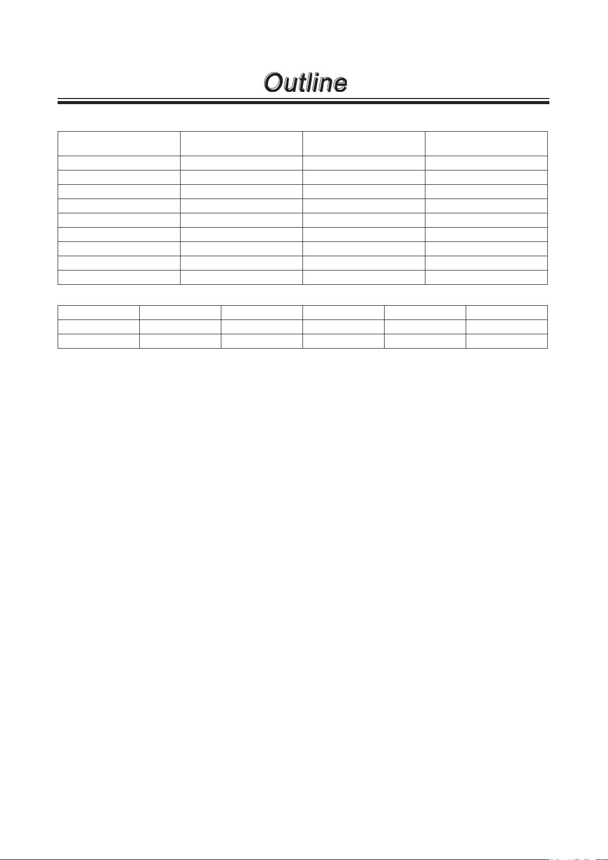
5. Dimension
MX-250/-251/-400/-401/-402(H)/-403(H)
Outline
MX-505
f
H
d e
c
L
g
f
W
b
a
b
4×k
H
d e
c
L
g
a
W
4×k
Model W H L a b c d e f g k
MX-250 160 247.5 411 130 65 130 115 140 90 163 12
MX-251 160 247.5 444 130 65 130 115 140 90 171 12
MX-251 (IE3) 160 247.5 446 130 65 130 115 140 90 171 12
MX-400 140 219 411 110 54 98 95 130 87 150 12
MX- 401 160 249 457 130 72 130 115 140 103 184 12
MX-401 (IE3) 160 249 459 130 72 130 115 140 103 184 12
MX-402(H)/-403(H) 260 274 516 208 80 200 120 160 89 157 14×36
MX-402(H)/-403(H)(IE3) 260 274 514/543 208 80 200 120 160 89 157 14×36
MX-505 180 330 601 140 96 220 150 180 95 175 14
NOTE: Actual dimensions may differ from the above information depending on model identification codes.
- 10 -
6. Part names
MX-250/-251/-401
13
Outline
9
5
2
19
20
8
21
23
13
24
11
24
1
12
3
22
18
9
27
15
16
No. Names Q'ty
Materials Remarks Materials Remarks Materials Remarks
MX-250 MX-251 MX-401
1 Front casing 1 GFRPP GFRPP GFRPP
2 Rear casing 1 GFRPP GFRPP GFRPP
3 Impeller 1 GFRPP GFRPP GFRPP
5 Drive magnet unit 1
8 Magnet capsule 1
Ferrite mag.
+aluminum alloy
Ferrite mag.
+PP
Ferrite mag.
+FCD450
Ferrite mag.
+PP
Ferrite mag.
+FCD450
Ferrite mag.
+PP
9 Hex socket set screw 2 Steel M8 × 10 Steel M8 × 10 Steel M8 × 10
11 Hex soch head bolt 6
12 Hex soch head bolt 2
Stainless
steel
Stainless
steel
M8 × 35,
with PW, SW
M8 × 50,
with PW, SW
Stainless
steel
Stainless
steel
M8 × 35,
with PW, SW
M8 × 50,
with PW, SW
Stainless
steel
Stainless
steel
M8 × 40,
with PW, SW
M8 × 50,
with PW, SW
13 Flange 2 GFRPP GFRPP GFRPP
15 Motor 1
16 Base 1 GFRPP GFRPP GFRPP
17 Adapter 1 FC200 FC200 FC200
No. Names Q'ty
CV/CE RV/RE AV/AE Remarks Remarks
Materials MX-250/-251 MX-401
18 Liner ring 1 Alumina ceramics 99.5%
19 Rear thrust 1 CFRPPS
20 Spindle 1 Alumina ceramics 99.5%
21 Bearing 1
High density
carbon
Filled PTFE
Alumina ce-
ramics
22 Mouth ring 1 Filled PTFE
23 O ring 1 V: FKM E: EPDM JIS B 2401 G165 JIS B 2401 G165
24 O ring 2 V: FKM E: EPDM JIS B 2401 G25 AS568-129
27 Hex soch head bolt 4 Steel
M8 × 20,
with PW, SW
M8 × 20,
with PW, SW
- 11 -
MX-400
13
Outline
15
9
5
2
19
20
8
23
21
13
24
11
24
3
22
18
27
9
16
1
12
No. Names Q'ty Materials Remarks No. Names Q'ty
1 Front casing 1 GFRPP 18 Liner ring 1
CV/CE RV/RE AV/AE
Materials Remarks
Alumina ceramics 99.5%
2 Rear casing 1 GFRPP 19 Rear thrust 1 CFRPPS
3 Impeller 1 GFRPP 20 Spindle 1
Drive mag-
5
net unit
Magnet cap-
8
Hex socket
9
set screw
Hex soch
11
head bolt
Hex soch
12
head bolt
sule
Ferrite magnet
1
+aluminum alloy
Ferrite magnet
1
+PP
21 Bearing 1 Carbon
22 Mouth ring 1 Filled PTFE
2 Steel M8 × 10 23 O ring 1 V: FKM E: EPDM
4
2
Stainless
steel
Stainless
steel
M8 × 30,
with PW, SW
M8 × 40,
with PW, SW
24 O ring 2 V: FKM E: EPDM
Hex soch
27
head bolt
Alumina ceramics 99.5%
Filled
PTFE
4 Steel
13 Flange 2 GFRPP
15 Motor 1
16 Base 1 GFRPP
17 Adapter 1 FC 200
Alumina
ceramics
99%
JIS B 2401
G135
AS568-129
M8 × 20,
with PW, SW
- 12 -

MX-402(H)/-403(H)
Outline
8
23
21
20
19
15
10
9
4
17
2
9
18
3
27
16
26
27
22
Materials Remarks
CV/CE RV/RE
Alumina ceramics 96%
14
25
11
24
13
1
12
No. Names Q'ty Materials Remarks No. Names Q'ty
1 Front casing 1 GFRPP 18 Liner ring 1
2 Rear casing 1 GFRPP 19 Rear thrust 1 CFRPEEK
3 Impeller 1 GFRPP 20 Spindle 1
Drive mag-
4
net unit
Magnet cap-
8
Hex socket
9
set screw
Hex head
10
Hex soch
11
head bolt
Hex soch
12
head bolt
sule
bolt
Rear earth
1
magnet
21 Bearing 1 Carbon Filled PTFE
+FCD450
Rear earth
1
magnet
+PP
22 Mouth ring 1 Filled PTFE
23 O ring 1 V: FKM E: EPDM
2 Steel M8 × 10 24 O ring 1 V: FKM E: EPDM
4
7
1
Stainless
steel
Stainless
steel
Stainless
steel
M10 × 30*,
with SW
M10 × 45,
with PW, SW
M10 × 60,
with PW, SW
25 O ring 1 V: FKM E: EPDM
Hex soch
26
head bolt
27 Lock pin 2 GFRPPS
Alumina ceramics 99.5%
4 Steel
13 Flange in 1 GFRPP
14 Flange out 1 GFRPP
15 Motor 1
16 Base 1 GFRPP
17 Adapter 1 FC200
JIS B 2401
G195
AS568-
136
AS568-
129
M8 × 20,
with PW, SW
*IE3 motor: M10×25
- 13 -

MX-505
13.1
13.2
Outline
10
9
4
17
2
9
19
20
21
27
8
3
27
14.1
14.2
11
25
24
12
23
22
1+18
15
No. Names Q'ty Materials Remarks No. Names Q'ty
1 Front casing 1 GFRPP 18 Liner ring 1
Materials
CV/CE RV/RE
Alumina ceramics 99.5%
2 Rear casing 1 GFRPP 19 Rear thrust 1 CFRPEEK
3 Impeller 1 GFRPP 20 Spindle 1
Alumina ceramics 99.5%
Rear earth
4 Drive magnet unit 1
magnet
21 Bearing 1 Carbon Filled PTFE
+FCD450
22 Mouth ring 1 Filled PTFE
23 O ring 1 V: FKM E: EPDM
25 O ring 1 V: FKM E: EPDM
27 Lock pin 2 GFRPPS
8 Magnet capsule 1
Hex socket set
9
screw
10 Hex head bolt 4
Hex soch head
11
12
bolt
Hex soch head
bolt
Rear earth
magnet
+PP
2 Steel M8 × 10 24 O ring 1 V: FKM E: EPDM
M12 × 35,
with SW
M10 × 45,
with PW, SW
M10 × 75,
with PW, SW
6
2
Stainless
steel
Stainless
steel
Stainless
steel
13.1 Flange in inner 1 GFRPP
13.2 Flange in outer 1 GFRPP
14.1 Flange out inner 1 GFRPP
14.2 Flange out outer 1 GFRPP
Remarks
JIS B 2401
G230
JIS B 2401
G70
JIS B 2401
G55
15 Motor 1
17 Adapter 1 FC200
- 14 -

7. Overview
Outline
Pump unit
Not capable of self-priming.
Prime the pump via inlet or
outlet before operation.
Outlet
Motor nameplate
Apply the power voltage specified on the
nameplate (follow an applicable local
power regulation.)
"Arrow" label
The arrow indicates a rotational direction of
the motor. Make sure the motor runs in a correct direction. Refer to page 27, "2. Before
operation".
Motor (Drive unit)
The motor power is transmitted to
the pump.
Base
Be sure to fix the base.
Pump nameplate
Operate the pump in accordance
Inlet
with specifications.
"Do not run pump dry" label
Operating the pump without liquid
damages internal parts.
CAUTION
Wet a cloth with tap water and wring it out for cleaning the pump. Use a neutral detergent for greasy dirt and then rub with a dry cloth. Do not wipe nameplates, labels or
pump body with any solvent.
- 15 -

Installation
1. Before installation ...............................17
2. Installation/Pipework/Wiring ...............19
- 16 -

Installation
CAUTION
● Do not run pump dry
Do not run pump dry (operation without priming water or with a suction valve
closed). Otherwise, internal parts are excessively worn by friction heat and
fatal pump damage results.
* If the pump runs dry by mistake, turn off power and leave it for more than
one hour to cool it down. Quick cooling can give rise to cracks on parts.
* An Iwaki dry run protector, the DR, is recommended for the prevention of
dry running.
● Do not operate the pump in a flammable atmosphere
Do not place explosive or ammable material near the pump.
● Do not modify the pump
Alterations to the pump carries a high degree of risk. It is not the manufacturer’s responsibility for any failure or injury resulting from alterations to the
pump.
Prohibit
Prohibit
Prohibit
1. Before installation
Always observe the following points.
■ Precautions for starting/stopping the pump
(In case the pump is in flooded suction system.)
Follow the procedures below when starting/stopping the pump for the prevention of water hammer.
Take extra care when a discharge line is long.
When starting the pump
First, prime the pump. Then turn on power to start operation with a discharge valve fully closed.
And then gradually open the valve and adjust a flow rate to a specified point.
When stopping the pump
Gradually close a discharge valve. Turn off power and stop the pump after the valve is fully closed.
NOTE: Do not close a discharge valve sharply. Otherwise an excessive pressure may dam-
age the pump, when using a solenoid valve, set it to close slowly.
■ Do not install or store the pump:
• Where ambient temperature can exceed 40 ºC or falls below 0 ºC.
• Where ambient humidity can exceed 85%RH or falls below 35%RH.
• In a corrosive/explosive environment.
• In direct sunlight or wind & rain (except outdoor-use type).
• Under mechanical vibration.
- 17 -

Installation
■ Always prime the pump
The MX is not a self-priming pump. Prime the pump every time the pump is operated. Do not run pump dry
(operation without liquid.), or internal parts seizing or excessive wear results.
■ Maximum operating pressure
Do not allow a discharge pressure to exceed the limits below.
Model MX-250 MX-251 MX- 400 MX-401
Pressrue limits (MPa) 0.25 0.33 0.22 0.28 0.43 0.5 0.33
MX-402
/-403
■ Liquid conditions
Slurry
The MX series can not send slurry except the pumps with a SiC bearing and a SiC spindle (sliding parts
code: A).
The A type can handle slurry up to 5% (concentration), 50μm (particle size) and 80Hs (hardness).
Contact us for details.
Performance change
Shaft power, discharge capacity and pump head vary depending on specic gravity and viscosity. The
pump is designed for a specied liquid. If you made a change to the liquid property, contact us.
SiC bearing
A SiC bearing can be worn greater than other materials depending on liquid property including liquid viscosity. Contact us for detail.
Temperature change
Viscosity, vapour pressure and corrosive nature vary with liquid temperature. Always take account of temperature change.
MX-402(H)
/-403(H)
MX-505
►Allowable liquid temperatrue: 0-80°C (clean water)
►Allowable ambient temperature: 0-40°C
►Allowable ambient humidity: 35-85%RH
NOTE: Contact us for the allowable liquid temperature range at each liquid type.
■ Intermittent operation
Frequent ON-OFF operation damages the pump in a short time. Do not make ON-OFF operation more than
six times per hour.
■ Disconnection of magnet coupling
Stop the pump immediately when the magnet coupling is disconnected. Otherwise magnetic force reduces.
■ Ascending area of a spike curve (in a performance curve)
When a specified point falls on an ascending area of a spike curve (generally, a flow is small in this area.
See the standard performance curves), check and observe the following points.
• There should be no possibility of trapping air in a supply tank or a discharge line.
• A discharge valve should be installed near the pump outlet to adjust a flow rate.
- 18 -

Installation
2. Installation/ Pipework/ Wiring
If you notice any abnormal or dangerous conditions, suspend operation immediately
and inspect/solve problems.
WARNING
● Turn off power before work
Be sure to turn off power to stop the pump and related devices before work.
Make sure no one turns on power by mistake while working on the pump,
otherwise it may result in a serious accident. If your working area is noisy or
dark, let other people know about the situation by displaying a notice such as
"POWER OFF (Maintenance)" near a power switch.
Do not lift the pump by gripping any plastic parts (pump unit, flange or base)
●
The pump can drop unintentionally as a plastic part breaks, resulting in seri-
Turning off power
ous injury.
● Electrical wiring
Electrical work should be performed by a qualified electrician. Otherwise,
personal injury or property damage may result.
■ Carrying in and out
When carrying in and out the pump, observe the following points.
• Do not lift the pump by holding plastic parts such as a pump unit, a flange or a base.
• Mount the pump horizontally on a pump base.
Caution
- 19 -

Installation
■ Installation
Arrange pump and pipework based on the following piping layout for a long period of operation.
1
16
12
12
15
5
9
17
7
2
1011
12
2
6
15
2
2
14
13
Installation location
• Install the pump as close to a supply tank. Keep a liquid level in the tank higher than the pump at any time
(flooded suction application).
• In case the pump is installed above a liquid level (suction lift application), lay on a priming line and mount a
foot valve to the bottom of a suction line.
1. Discharge pipe
2
3
4
( Support pipework to keep the pump free of
piping weigh.)
2. Gate valve
3. Check valve
4. Pressure gauge
5. Motor
6. Pump
7. Air vent/ priming line
9. Drain ditch
10. Vacuum gauge
11. Suction pipe (Pipe diameter: D)
( Horizontal sections should be shortest and
laid on a rising gradient of 1/100 toward the
pump)
12. Pipe support
13. Suction pipe (Pipe diameter: D)
14. 2D or 500mm or more
15. Expansion joint
16. Flushing line (Discharge side)
17. Flushing line (Suction side)
NOTE: The maximum suction lift varies with liquid characteristics, specific gravity, liquid
temperature and suction line length. Contact us for detail.
Outdoor use motors (Indoor use motors can not be installed out of doors)
Outdoor use motors can also be used in doors. Protect the motor and electrical power distribution equipment from possible damage due to an accidental outflow or act of providence.
Installation space
• Select a level location, free from vibration, that won’t hold liquid.
• Allow sufficient space around the pump for easy access and maintenance.
CAUTION
Fix the pump firmly. Support piping so as not to directory weigh on the pump.
- 20 -

■ Foundation work
Installation
Foundation bolt
Shim
Base
Liner
Concrete
• Installation area should be larger than the footprint of the pump. Or a plastic base may break
due to a concentrated load.
• If piping vibrates sympathetically with the
pump in operation, provide an expansion joint
between the pump and the piping to reduce
vibration.
■ Tightening torque between the pump and pipework
Connect the pump to pipework via inlet and outlet flanges according to the tightening torque below. The
table is based on use of metal pipe flanges with rubber gaskets. Tighten bolts diagonally at even torque.
Model Bolt size Tightening torque
MX-250/-251/-400/-401/-402/-403/-505 M16 20N•m
■ Piping load and momentum
Try not to apply a heavy load to the inlet and outlet flanges. Permissible piping weight and moment to the
pump are as below.
Y
Z
Y
Z
X
X
- 21 -

Installation
Permissible stress to outlet flange Permissible stress to inlet flange
Pipe dia. (mm)
kN
40, 50
Load direction
Fx
Fy
Fz
40, 50
Load direction
Mx
25
Load
Load direction
Fx
Fy: compression
Fy: tension
Fz
Permissible moment to outlet flange Permissible moment to inlet flange
Load direction
Mx
0.10 0.15
0.15 0.20
0.10 0.10
0.10 0.15
Pipe dia. (mm)
25
Moment
kN·m
0.02 0.05
Pipe dia. (mm)
25
Load
kN
0.10 0.10
0.10 0.15
0.10 0.15
Pipe dia. (mm)
25
Moment
kN·m
0.05 0.10
40, 50, 65
40, 50, 65
My
Mz
0.05 0.10
0.05 0.10
My
Mz
0.02 0.05
0.05 0.10
■ Suction line
1. Always build up a flooded suction system. Have a suction line shortest with the minimum number of
bends. Support piping by pipe supports so that the pump is not subject to piping weight or thermal stress.
2. Make sure joints on a suction line are secure and air doesn't come in. If air is entrained into a suction line,
liquid may not be pumped or the pump may break at its worst.
3. When the inner pressure of a supply tank is negative, or a suction lift or a suction line is long, apply the
following formula.
NPSHa>NPSHr+0.5m (See the standard performance curve for NPSHr.)
4. If a bent pipe is installed in a suction line, lay a straight line (length: 500mm or longer, or 8 times longer
than the inlet I.D. of the pump) between a pump inlet and the bent pipe. Also, have the curvature radius of
the bent pipe largest.
5. Do not allow any arched line where air may be trapped. A suction line should be laid on a rising gradient
of 1/100 toward the pump.
6. If the inlet I.D. of the pump is different from that of a suction pipe, use an eccentric reducer pipe. Upper
side should always be level. Air may be trapped if it is mounted upside down.
- 22 -

Installation
7. In flooded suction, install a gate valve on a suction line for easier overhaul & inspection. Keep this valve
open at any time during operation.
8. Install a flushing line for cleaning the pump after handling a harmful liquid.
9. A suction pipe I.D. should be equal to or larger than a pump inlet I.D.
Suction lift application
10. One end of a suction line should always be at least 500 mm lower than a liquid level in a supply tank for
the prevention of air ingress.
11. Provide a screen in a supply tank for the prevention of foreign matter interfusion (Clean the screen peri-
odically.). The distance between the end of a suction line and the bottom of a suction tank should be 1.5
times wider than a suction line I.D.
12. Be sure to install a foot valve at one end of a suction line.
Good conditions Unacceptable conditions
Trapped air
Trapped air
Trapped air
- 23 -

Installation
■ Discharge line
1. Support discharge piping so as not to directory weigh on the pump.
2. Lay a priming line when the pump is not under a flooded suction system.
3. Pipe resistance rises too high to obtain an intended flow if a discharge pipe I.D. is too long. Always take
account of the increment of pipe resistance.
4. Install a check valve in the following cases.
When selecting a check valve, check its maximum operating pressure to make sure it tolerates a possible
pressure rise due to water hammer or backflow.
• A discharge line is too long.
• Actual discharge head (static discharge head plus discharge pipe resistance) is more than 15m.
• The end of a discharge line is 9m higher than a liquid level in a supply tank.
• Several pumps are running in parallel.
5. Install a gate valve on a discharge line to adjust a flow rate and to protect a motor from overload. If you
are to install a check valve as necessary, it should be mounted in between the pump and the gate valve.
6. Install a pressure gauge on a discharge line.
7. Install an air vent line when a discharge line is laid long in a horizontal direction.
8. Drain
Install a drain valve if there is the risk of liquid freezing in the discharge line.
■ Wiring
Electrical wiring and any work on power source must be performed by qualified persons only. It is not the
manufacturer’s responsibility for any injury and damage due to noncompliance with this notice. Contact us
as necessary.
1. Install an electromagnetic switch according to motor specifications (voltage, capacity, etc.).
2. Electromagnetic switches and push buttons should be installed away from the pump.
3. If the pump is used out of doors, protect switches from rainwater.
- 24 -

Operation
1. Operational precautions ......................26
2. Before operation .................................27
3. Operation ............................................27
- 25 -

Prohibit
Operation
1. Operational precautions
CAUTION
● Never run pump dry or shut off a suction valve during operation. Otherwise
the pump fails in a short period.
● Check the rotational direction of the pump. Clockwise seen from the motor
end is a correct direction. Operation in a reverse direction may cause
pump damage.
● Stop the pump immediately when it is running under cavitation. Do not
continue to run the pump when air is entrained from a suction line.
● Stop the pump immediately if the magnet coupling is disconnected.
Magnetic force reduces if the pump keeps on running for more than one
minute in this condition.
Keep liquid temperature change within 80˚C at any time during operation or stop.
●
● Start the pump with a discharge valve fully closed in order to avoid water
hammer.
● Closed-discharge operation should be within one minute. If the pump runs
with a discharge valve closed for a long time, the liquid temperature inside
the pump rises and damages the pump.
● If power is interrupted while the pump is running, switch off the pump
immediately and close a discharge valve.
● Take extra care for a discharge pressure not to exceed the pump limit. See
page 18, "Maximum operating pressure".
● The surface temperature of the pump or pipe rises high along with liquid
temperature in or right after operation. Take preventive measures.
Model Liquid temperatuer Surface temperature (at ambent 40°C)
MX-250/-251/-400/-401/-402(H)/-403(H)/-505 80°C 80°C
● Noise level
Model MX-250/-400 MX-251/- 401
Noise level 70dB 75dB 80dB 85dB
MX-402(H)/-403(H)
MX-505
Caution
Caution
In case the pump noise affects human health or communication to secure
a safety, provide a noise reduction cover. Be careful not to reduce cooling
effect by a motor fan.
- 26 -

Operation
2. Before operation
Take the next steps to start the pump at the first operation or after a long period of storage.
1. Clean the inside of piping and a supply tank.
2. Retighten flange fixing bolts and base fixing bolts.
3. Prime the pump and shut off a discharge valve. Check an air vent line and a flushing line are closed.
4. Run the motor for a moment (within a second) in order to check if the motor rotates to the direction pointed by an arrow label (clockwise seen from a motor fan). If the motor rotates in reverse, interchange two of
three phase wires at random.
3. Operation
■ Starting process
Operate the pump by the following procedure.
Operation procedure Remarks
• Open valves. • Open suction valves fully.
1
2
• Prime the pump. • Prime the pump unit and then close a discharge valve.
• Check the motor for correct
rotating direction.
Turn on power and then
3
immediately (within one second) switch off the power.
• Turn on power and start the
pump to adjust discharge
pressure and capacity.
Observer the minimum discharge capacity. See below.
4
• Open discharge valves fully.
• Supply power to run the pump only for checking a rotational direction. (The
correct direction is indicated with an arrow on the motor.)
• Check if the motor fan smoothly stops after the power is turned off.
CAUTION
If the motor fan does not stop smoothly, internal parts may
contact each other. Check the inside of the pump.
• Run the pump with a discharge valve closed. Once a pressure gauge points
the max discharge pressure, open the discharge valve gradually to obtain a
specified discharge pressure (or discharge capacity).
NOTE: Start to open/close a discharge valve gradually to adjust dis-
charge pressure within one minute after the pump starts to run.
Always check a discharge pressure gauge (or adjust discharge
capacity by checking a flow meter).
CAUTION
Opening a valve sharply, the motor may be overloaded.
Always open a valve while checking ammeters.
- 27 -

Operation
Operation procedure Remarks
Do not operate the pump below the minimum discharge capacity.
►The minimum discharge capacity: 10
• Observe the minimum discharge capacity for the prevention of continuous closed-discharge operation. This
4
rule holds true to not only manual operation but also automatic operation.
CAUTION
Do not run the pump longer than one minute with a discharge valve fully closed.
< Points to be checked>
Check a flow meter and con-
5
firm that pump operation is
as per specifications during
operation.
/min MX-250/-251/-400/- 401
20
/min MX-402(H)/-403(H)
50
/min MX-505
• If a flow meter is not available, calculate a flow rate from discharge pressure,
suction pressure and current value, taking account of pipe resistance.
CAUTION
In case of trouble, turn off power immediately and solve problems. See “1.
Troubleshooting”.
■ Stopping process
Operation Procedure Remarks
• Close a discharge valve
gradually.
1
• Turn off power and stop
2
pump operation.
<Leaving the pump stop>
• Liquid in the pump may freeze and consequently damage the pump in winter. Drain liquid before storage. When
draining harmful liquid, be sure to flush the inside of the pump and piping afterwards.
3
• Use a heater to prevent liquid from freezing when the pump is temporarily stopped in an extremely cold region.
• In the event of a power failure, turn off power and close a discharge valve.
• Do not close a discharge valve sharply whether manually or automatically.
Otherwise, the pump may be damaged by water hammer action which tends to
occur with a long a discharge line. When using a solenoid valve, set it to close
slowly.
• Check that the motor stops slowly and smoothly. If it does not stop smoothly,
inspect the inside of the pump.
- 28 -

Maintenance
1. Troubleshooting ..................................30
2. Maintenance & Inspection...................31
3. Spare & Wear parts ............................34
4. Dismantlement & Assembly ................35
- 29 -

Maintenance
1. Troubleshooting
If you can not find out the root cause of failure, contact us.
Symptom
Troubles
Liquid can not
be discharged.
Discharge
capacity is too
low.
Motor is overheated.
Discharge
capacity is rapidly reduced.
Pump vibrates.
When a discharge
valve is closed.
The pump can not be
primed.
After starting, pressure drops sharply as
a discharge valve is
opened.
Discharge pressure
does not rise.
Pressure & vacuum
are normal.
Pressure is low and
vacuum is very low.
When a discharge
valve is opened.
The readings of pressure/vacuum gauges
drop to zero.
The readings of pressure/vacuum gauges
fluctuate and drop to
zero.
Vacuum is high.
Vacuum is very high.
The readings of pressure gauge & vacuum gauge fluctuate.
Vacuum is high but
pressure is normal.
Vacuum is normal
but pressure is high.
Pressure and vacu-
um are low.
Vacuum is high. • A suction line clogs with
• Priming liquid level is too
low.
• Dry running
• A foot valve doesn't close
due to foreign matter clogging.
• Air ingress through a
suction line or a sealing
surface.
• A disconnection of the
magnet coupling
• Low pump speed
• The pump rotates in
reverse.
• The strainer is clogged
with foreign matters.
• Air pocket in suction line
• Foreign matters are
clogged at impeller inlet.
• Air ingress from a suction
line or a sealing surface.
• Discharge line clogs with
foreign matters.
• Resistance such as air
pocket in suction line.
• Actual head is too high or
pipe resistance is too large.
• Motor rotates in reverse. • Interchange motor wiring.
• Power voltage is low.
• Overload
foreign matters.
• Poor foundation
• Loose mounting bolts.
• Cavitation occurs.
• Pump bearing is worn or
melted.
• Magnet capsule or spindle
is broken.
• Dynamic balance of drive
magnet is upset.
• The rotating part hits
against other parts.
• Motor bearing is worn.
Cause
Point to be checked
&
Countermeasures
• Stop and prime the pump
and resume operation.
• Clean the foot valve and
a seat.
• Check if suction line connections are completely
sealed.
• Check if liquid level in
supply tank is not too low.
• Check amperage to see
if the motor is not overloaded.
• Check if foreign matters
do not lock the impeller or
magnet capsule.
• Check if voltage is normal.
• Check wiring or motor.
• Correct wiring.
• Remove foreign matters.
• Check and correct suction
line.
• Remove foreign matters.
• Check suction line con-
nections and retighten as
necessary.
Remove foreign matters or
•
scale from pump/piping.
• Check if there is no
arched pipework.
• Check actual head and
pipe resistance.
• Check voltage or frequency.
• Check specific gravity and
viscosity of liquid.
• Keep good ventilation.
• Remove foreign matters.
• Reinstall the pump.
• Retighten the bolts.
• Remove the cause of
cavitation.
• Replace as necessary.
• Replace as necessary.
• Remove the cause.
Replace as necessary.
• Replace as necessary.
• Replace bearing or motor.
- 30 -

Maintenance
2. Maintenance & Inspection
WARNING
● Access limitation
The magnet drive pump has a pair of strong magnets. The strong magnet field
could adversely affect the persons who are assisted by electronic devices
such as the pacemaker.
● Turn off power before service
Risk of electrical shock. Be sure to turn off power to stop the pump and related
Prohibited
devices before service is performed.
● Wear protective clothing
Always wear protective clothing such as an eye protection, chemical resistant
gloves, a mask and a face shield during disassembly, assembly or mainte-
nance work. The specic solution will dictate the degree of protection. Refer to
MSDS precautions from the solution supplier.
CAUTION
● Do not catch the finger
Magnetic force of the pump is powerful. Take care not to catch the finger in
the bracket.
■ Daily inspection
1. Always check for leakage before pump operation. Do not run the pump when liquid leaks.
2. Check whether the pump runs without abnormal noise or vibration.
Turning off power
Wear protective
gear
Caution
3. Check a liquid level in a supply tank and a suction pressure.
4. Check that discharge capacity and a motor current value are as per specifications on the nameplate during operation.
NOTE A discharge pressure is in proportion to the specific gravity of liquid. The cock of a
pressure gauge or a vacuum gauge should be opened only when measurement is
carried out. Close it right after measurement. If the cock remains open during pump
operation, its meter mechanism may be adversely affected by the abnormal pressure rise caused by water hammer action.
5. If a spare pump is stored, run it from time to time to keep it ready for operation at any time when needed.
6. Check discharge pressure, discharge capacity, and motor power supply voltage to see if they do not fluc-
tuate during pump operation. See page 30 "1. Troubleshooting" as necessary.
- 31 -

Maintenance
■ Periodic inspection
To ensure efficient and smooth operation, perform periodic inspection. Be careful not to damage internal
sliding parts and plastic parts when dismantling the pump.
The magnetic force of a drive and a driven magnet is strong. Be careful not to catch the finger. Do not put
electrical devices such as a watch and a mag card close to those magnets.
Interval
Every six months
(Maintain an
inspection record)
Part names
(Drive magnet unit)
Drive magnet
Hex. socket set screw
Rear casing
Rear thrust
(Magnet capsule unit)
Magnet capsule
Bearing
(Impeller unit)
Impeller
Mouth ring
Inspection items
● Wear trace
● If the drive magnet is correctly
mounted by hex. socket set
screws and they are not loose.
● Decentering of magnet and
motor shaft (Max.1/10mm)
● Wear tracks on an inner surface
● Cracks
● Wear of the rear thrust
● Contamination in rear casing
● Wear tracks on the rear end or
side face of the magnet capsule
● Cracks on the rear end or side
face of the magnet capsule
● Wear of the bearing
● Loose fit of the impeller unit
● Wear of the mouth ring
● Cracks
● Contamination in the impeller
● Impeller deformation
Measures
○ Finding wear trace, contact us.
○ Reset the drive magnet to the
motor shaft and retighten the
screws.
○ Retighten the hex. socket set
screws or replace the drive
magnet (Contact us).
○ Contact us.
○ Replace as necessary.
○ Contact us.
○ Remove contamination.
○ Contact us.
○ Contact us.
○ Replace as necessary.
○ Replace or contact us.
○ Replace as necessary.
○ Replace as necessary.
○ Remove contamination.
○ Replace as necessary.
Front case
Rear case
Liner ring
Spindle
● Contamination
● Cracks
● Wear, cracks and wear tracks
on a liner ring
● Swelling or a crack on O ring
● Wear tracks on an unlikely portion
● Cracks
● Wear degree
- 32 -
○ Remove contamination.
○ Replace as necessary.
○ Contact us.
○ Replace as necessary.
○ Contact us.
○ Replace as necessary.
○ Replace as necessary.

Maintenance
■ Wear limits of bearing and spindle
Check wear degree of the bearing and spindle.
Model
Bearing inner diameter 18 19 24 25
Spindle outer diameter 18 17 24 23
* If the clearance between the bearing (#21) and the spindle (#20) exceeds 1 mm, either of them, whichever
has greater wear, should be replaced regardless of the wear limit. For the pumps with the SiC spindle and
SiC bearing (MX-250/-251/-400/-401), replace the both parts at the same time (the whole magnet capsule
unit of #8 needs changed to the new one to replace the bearing).
* Sliding parts may suffer initial wear in an initial operation phase but this is not abnormal.
■ Wear limit of mouth ring
Check wear degree of the mouth ring.
Model
MX-250/-251/-400/-401 MX-402/-402(H)/-403/-403(H)/-505
Before use Wear limit Before use Wear limit
Mouth ring thickness
Initial thickness Wear limit
MX-250/-251/-400/-401/-402(H)/-403(H) 8mm 6mm
MX-505 9mm 7mm
* The mouth ring (#22) is 2 mm (3m for MX-250) forward from the impeller (#3) when shipped. Before the
step has reduced to 0 mm, replace the impeller unit.
Max 2mm
Mouth ring
Impeller
- 33 -

Maintenance
3. Spare & Wear parts
Appropriate spare parts are necessary for a long period of continuous operation. We recommend
that wear parts be always in stock. Place an order for spares with the following information.
1. Part names and part number (See the diagram below.)
2. Pump model identification code and manufacturing number (See pump nameplate.)
3. Drawing number if you have our approval drawing
■ Spare parts list
No. Part name MX-250 MX-251 MX-400 MX-401 MX-402 MX-403 MX-402H MX-403H MX-505
1 Front casing unit MX0109 MX0125 MX0131 MX0799 MX0804 MX0983
2 Rear casing MX0110 MX0126 MX0132 MX0802 MX0807 MX0967
IE1 M X0111 - MX0127 - MX0176 MX0184 MX0190 MX0191 MX0969
29 Impeller unit 50Hz
29 Impeller unit 60Hz
Magnet capsule unit C
8
(carbon)
Magnet capsule unit R
8
(PTFE)
Magnet capsule unit A
8
(Alumina ceramic)
O ring (for casing) V M X 0116 MX0129 MX0 116 MX0180 MX0 974
23
O ring (for flange) V M X 0117 MX013 0 MX0181 MX0978
24
O ring (for flange) V - - MX0130 MX0976
25
20 Spindle MX0 118 MX0182
19 Rear thrust MX0 119 MX0183
13
Flange
14 - - MX0299
27 Lock pin - MX0308
Note1: The O ring part numbers above are for FKM and EPDM. Contact us for the Aflas® O ring.
Note2: The maximum duration of the above parts (except #23, #24 and #25 O rings) is about 20,000 hours, however, it is based
on the operation with clean water at ambient temperature and can change with liquid properties and temperature.
For the #23, #24 and #25 O rings, they should be replaced every time the pump head is opened.
Note3: The #20 spindle, #21 bearing and #22 mouth ring must be replaced when the wear limit has come. Note the whole
magnet capsule unit (#8) needs to be changed to the new for the replacement of the bearing, and the whole impeller unit (#29) for the replacement of the mouth ring.
13
24
11
24
13
12
IE2 MX0991 MX0935 MX0993 MX0937 M X0176 MX0184 MX0190 MX0191 MX0969
IE3 - MX0120 - MX1016 MX0176 MX018 4 MX0190 MX0191 MX0969
IE1 MX0112 - MX0128 - MX017 7 MX0185 MX0185 MX0176 MX0968
IE3 - MX0121 - M X1017 MX0177 MX0185 MX0185 MX0176 MX0968
MX0 113 MX0122 M X0113 MX0122 M X0178 MX0186 MX0178 MX0186
MX0 114 MX0123 M X0114 MX0123 M X0179 MX0187 MX0179 MX0187
MX0 115 MX0124 M X011 5 MX0124 - - - - -
E MX0207 MX0235 MX0207 MX0302 MX0973
E MX0205 MX0233 MX0300 MX0977
E - - MX0233 MX0975
MX0204 MX0232 MX0298
2
19
20
8
8
21
23
29
3
22
18
1
14
25
11
24
13
12
29
3
27
22
18
1
8
8
23
21
27
13.1
20
13.2
2
19
14.1
27
29
14.2
11
25
24
22
1+18
12
(13.1) MX0980
(13.2) MX0979
(14.1) MX0982
(14.2) MX0981
23
3
27
19
8
20
8
21
2
MX-402/-403/-402H/-403HMX-250/-251/-400/-401 MX-505
- 34 -

Maintenance
Prohibited
4. Dismantlement & Assembly
WARNING
● Access limitation
The magnet drive pump has a pair of strong magnets. The strong magnet field
could adversely affect the persons who are assisted by electronic devices
such as the pacemaker.
● Turn off power before service
Risk of electrical shock. Be sure to turn off power to stop the pump and related devices before service is performed.
Turning off power
● Wear protective clothing
Always wear protective clothing such as an eye protection, chemical resistant
gloves, a mask and a face shield during disassembly, assembly or maintenance work. The specific solution will dictate the degree of protection. Refer to
Wear protective
gear
MSDS precautions from the solution supplier.
CAUTION
● Do not catch the finger
Magnetic force of the pump is powerful. Take care not to catch the finger in
the bracket.
► Mark each wire so that the wires can be connected correctly to the motor.
► Do not disassemble the pump beyond the extent shown on this manual.
► Make sure to close suction and discharge valves before dismantling/assembling the pump. Clean the
inside of the pump as well.
► Magnetic force of the pump is strong. Be careful not to catch the finger in parts. Do not allow iron
pieces or powders to stick to a drive and a driven magnet.
► A pair of strong magnets is mounted in the pump and its magnetic force may affect magnetic disks/
cards or wrist watches. Do not bring them close to the pump.
Caution
- 35 -

Maintenance
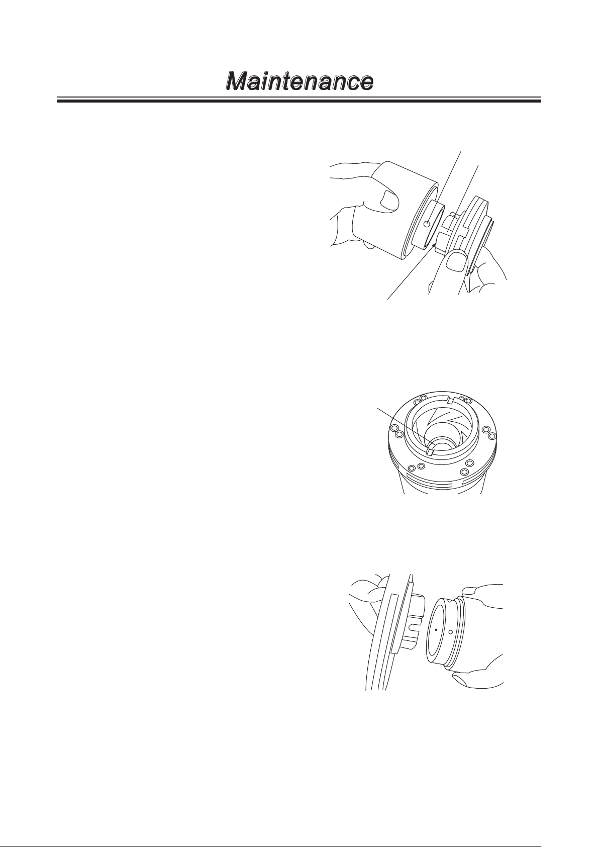
■ Disassembly (pump head)
1. Remove hex. socket head bolts from the front
casing and remove it from the motor bracket.
At this time drain and collect residual liquid and
decontaminate wet ends.
2. Pull out the combination of an impeller unit and a
magnet capsule unit. Be careful not to catch the
finger in the impeller unit and the bracket.
Magnet capsule unit
Impeller unit
3. Detach the impeller unit from the magnet capsule
unit as necessary. Be careful not to damage the
units.
a. MX-250/-251/-400/-401
Slightly tap the back of the impeller unit by a
plastic hammer while holding the magnet capsule unit. If it is hard to remove, warm them in
hot water (about 90°C) for five minutes.
Be careful not to get scalded with hot water..
- 36 -

Maintenance
b. MX-402(H)/-403(H)/-505
Turn two lock pins 90 degrees anticlockwise
using a flathead screwdriver and then push
them off inwards. Tap the end of driver handle
if necessary.
The lock pins can also be turned by using a
4mm hex. wrench from the inner surface of
the magnet capsule unit. In this case turn the
wrench clockwise. Note the pins will be damaged if they are turned in a reverse direction.
After unlocking, push it off from the outside by
using a bar.
Lock pin
After the lock pins are removed, detach the
impeller unit from the magnet capsule unit by
slightly tapping the back of the impeller unit
with a plastic hammer. If the impeller unit is
hardly removed, warm it in hot water (approx.
90°C) for five minutes and tap the back slightly. Be careful not to scald in hot water.
The impeller unit can not be separated from
the magnet capsule unit unless the lock pins
are removed. Do not use excessive force to
remove the impeller unit.
4. Slide the top of a flathead screw driver in
between the rear casing and the motor bracket to
pull out the casing. Pay attention not to scratch
the O ring surface.
Rear casing
- 37 -
Maintenance
■ Assembly (pump head)
1. Mount the impeller unit to the magnet capsule
unit.
a. MX-250/-251/-400/-401
Slide the impeller unit down into the magnet
capsule unit as far as it will go, locating the
U-shape holes under the through holes.
Through-hole
U-shape hole
The end of
press-fitting part
Check that the end of press-fitting parts has
come at a bearing surface. If the impeller unit
can not be fitted to the magnet capsule unit,
warm the magnet capsule unit in hot water
(about 90°C for five minutes) for softening. Be
careful not to get scalded with hot water.
b. MX-402(H)/-403(H)/-505
The mating surface on the magnet capsule
unit has two hole sizes. Large holes (stepped
holes of I.D. 6mm and 12mm) are for the lock
pins and the small holes (I.D. 3mm) are for
cooling. Slide down the impeller unit into the
magnet capsule as far as it will go, locating
the U-shape holes under the smaller holes. If
it is hard to combine them, warm the magnet
capsule unit in hot water (approx. 90°C) for 5
minutes. Be careful not to scald at this time.
Check no clearance between the
bearing surface
and the pressfitting parts.
- 38 -

Maintenance
After fitting the impeller unit, insert two lock
pins all the way seated in the lock pin holes
from an inner surface.
Use a flathead screwdriver to turn the pins
90 degrees clockwise from the outside while
holding the pins from the inside. Once it
clicks, the impeller unit is secured.
If the screw groove is deformed and can not
be used, the pins can be turned from the
inner surface with a 4mm hex. wrench. In
this case turn the wrench anticlockwise. Note
these plastic pins may be broken if it is turned
in reverse.
Lock pin
2. Insert the combination of the impeller unit and
the magnet capsule unit into the rear casing
slowly.
Do not allow foreign matters such as iron pieces
to adhere to the magnet capsule unit.
3. Mount the rear casing with the combined units in
it to the bracket.
CAUTION
Magnet force is very powerful. Place plastic or wooden spacers between the rear
casing and the motor bracket so as not to
catch the fingers.
Pay extra attention to for MX-402/-403 in
this point.
Bracket
Spacer
Impeller
- 39 -

Maintenance
4. Fit an O ring to the front casing. Check that sealing surfaces are free of dust or scratches. Make sure that
an O ring is in place and will not be out of a groove.
Mount the front casing to the rear casing according to a pair of mating parts (except the MX-400/-505).
Note that the MX-402 and -403 have two pairs of mating parts.
Rear casing
5. Fasten the front casing to the motor bracket.
Tighten the hex. socket bolts evenly. Tightening torque is shown below.
Model Tightening torque
MX-250/-251/-400/-401 11.8N•m
MX-402/-402(H)/-403/-403(H)/-505 14.7N•m
Mating parts
Front casing
- 40 -

Maintenance
■ Disassembly (loose flange)
<MX- 505>
1. Turn the combination of the outer and inner flange
counter clockwise to detach it from the pump inlet/
outlet. Use a belt wrench if necessary.
■ Assembly (loose flange)
<MX- 505>
1. Fit an O ring into the groove of the inner flange.
2. Combine the inner flange and the outer flange, using
the mating parts as a guide.
3. Turn the combination of the flanges clockwise until it
will not turn further.
NOTE: O ring may come out of the groove.
Keep it in place while tightening the
flanges.
Inner flange
Mating parts
Outer flange
Mating parts
O ring
O ring
Outer flange
Inner flange
Front casing
Mating parts
Mating parts
O ring
Gloove
- 41 -

European ofce
TEL: +49 2154 9254 0 FAX: +49 2154 9254 48
Germany
TEL: +49 2154 9254 50 FAX: +49 2154 9254 55
Holland
TEL: +31 74 2420011 FAX: +49 2154 9254 48
Italy
/ IWAKI Europe GmbH (Italy Branch)
TEL: +39 0444 371115 FAX: +39 0444 335350
Spain
/ IWAKI Europe GmbH (Spain Branch)
TEL: +34 93 37 70 198 FAX: +34 93 47 40 991
Belgium
TEL: +32 13 670200 FAX: FAX: +32 13 672030
Denmark
TEL: +45 48 242345 FAX: +45 48 242346
Finland
TEL: +358 9 2745810 FAX: +358 9 2742715
France
TEL: +33 1 69 63 33 70 FAX: +33 1 64 49 92 73
/ IWAKI Europe GmbH
/ IWAKI Europe GmbH
/ IWAKI Europe GmbH (Netherlands Branch)
/ IWAKI Belgium N.V.
/ IWAKI Nordic A/S
/ IWAKI Suomi Oy
/ IWAKI France S.A.
IWAKI CO.,LTD. 6-6 Kanda-Sudacho 2-chome Chiyoda-ku Tokyo 101-8558 Japan
Norway
/ IWAKI Norge AS
TEL: +47 23 38 49 00 FAX: +47 23 38 49 01
Sweden
/ IWAKI Sverige AB
TEL: +46 8 511 72900 FAX: +46 8 511 72922
U.K.
/ IWAKI Pumps (U.K.) LTD.
TEL: +44 1743 231363 FAX: +44 1743 366507
U.S.A.
/ IWAKI America Inc.
TEL: +1 508 429 1440 FAX: +1 508 429 1386
Argentina
TEL: +54 11 4745 4116
Singapore
TEL: +65 6316 2028 FAX: +65 6316 3221
Indonesia
TEL: +62 21 6906606 FAX: +62 21 6906612
Malaysia
TEL: +60 3 7803 8807 FAX: +60 3 7803 4800
/ IWAKI America Inc. (Argentina Branch)
/ IWAKI Singapore Pte Ltd.
/ IWAKI Singapore (Indonesia Branch)
/ IWAKIm SDN. BHD.
http://www.iwakipumps.jp
TEL: +81 3 3254 2935 FAX: +81 3 3252 8892
Australia
/ IWAKI Pumps Australia Pty Ltd.
TEL: +61 2 9899 2411 FAX: +61 2 9899 2421
China (Hong Kong)
TEL: +852 2607 1168 FAX: +852 2607 1000
China (Guangzhou) / GFTZ IWAKI Engineering & Trading Co., Ltd.
TEL: +86 20 84350603 FAX: +86 20 84359181
China
/ IWAKI Pumps (Shanghai) Co., Ltd.
TEL: +86 21 6272 7502 FAX: +86 21 6272 6929
Korea
/ IWAKI Korea Co., Ltd.
TEL: +82 2 2630 4800 FAX: +82 2 2630 4801
Taiwan
/ IWAKI Pumps Taiwan Co., Ltd.
TEL: +886 2 8227 6900 FAX: +886 2 8227 6818
Thailand
TEL: +66 2 322 2471 FAX: +66 2 322 2477
Vietnam
/ IWAKI Pumps Vietnam Co., Ltd.
TEL: +84 613 933456 FAX: +84 613 933399
/ IWAKI Pumps Co., Ltd.
/ IWAKI (Thailand) Co., Ltd.
T452-8 '15/07
 Loading...