

IWAKI PUMPS MDG-M4 series, MDG-M4T6B115L, MDG-M4T6B220H, MDG-M4S6B220, MDG-M4S6B115L Instruction Manual
...
IWAKI Magnet Gear Pump
MDG-M4 (built-in type)
Instruction Manual
Read this manual before use of product

This instruction manual includes descriptions of the correct
handling of the pump, maintenance and inspection procedures
and troubleshooting. You are requested to read the manual
carefully so that the pump can safely be used to the full extent
of its capacity for a long period of time.
Contents
Item
■
Safety Instruction ............................................ 3
■
Page
① Inspection after Unpacking ............................. 4
② Principle of operation ...................................... 4
③ Pump Identification Codes .............................. 5
④ Names of Parts and Structure .......................... 6
⑤ Precautionary measures .................................. 7
⑥ Installation, Piping and Wiring ....................... 9
⑦ Operation .........................................................11
⑧ Maintenance and Inspection ............................13
⑨ Disassembling and Reassembling ...................14
⑩ Causes of Trouble and Troubleshooting ..........16
⑪ Performance and Sizes ....................................17
⑫ Repair Service .................................................19
Export Restrictions
Technical information contained in this instruction manual might be treated as controlled
technology in your countries, due to agreements in international regime for export control.
Please be reminded that export license/permission could be required when this manual is
provided, due to export control regulations of your country.
— 2 —
Safety Instruction
CautionElectrical Shock
CautionElectrical Shock
CautionElectrical Shock
Prohibited
CautionElectrical Shock
GroundingWear protective
Prohibited
CautionElectrical Shock
Prohibited
CautionElectrical Shock
Prohibited
CautionElectrical Shock
Prohibited
CautionElectrical Shock
Prohibited
CautionElectrical Shock
Prohibited
CautionElectrical Shock
Prohibited
CautionElectrical Shock
CautionElectrical Shock
CautionElectrical Shock
CautionElectrical Shock
CautionElectrical Shock
No Remodeling
Prohibited
GroundingWear protective
CautionElectrical Shock
GroundingWear protective
gear
CautionElectrical Shock
CautionElectrical Shock
CautionElectrical Shock
Warning
Turn off the power supply.
●
Working without disconnecting the power supply may
cause an electrical shock. Before engaging upon any
working procedures involving the pump, make sure to turn
the power supply switch off and to stop the pump and
other related devices.
Terminate operation!
●
When you detect or become aware of a dangerous sign or
abnormal condition during operation, terminate the
operation immediately and start it from the beginning
again.
For specified application only.
●
The use of a pump in an application other than those
clearly specified may result in injury or damage to the
pump. Use the pump strictly in accordance with the pump
specifications and application range.
No remodeling!
●
Never remodel a pump. Otherwise, a serious accident
may result. Iwaki will not be responsible for any accident
or damage of any kind which is caused by the user
remodeling the pump without first obtaining permission or
instructions from Iwaki.
Wear protectors.
●
If you touch or come in contact with any type of
hazardous chemical liquid, including but not limited to
chemicals, you may experience a serious injury. Wear
protective gear (protective mask, gloves, etc.) during the
pump operation.
Caution
Qualified operators only!
●
The pump operator and pump operation supervisor must
not allow any operators who have little or no knowledge
of the pump to run or operate the pump. Pump operators
must have a sound knowledge of the pump and its
operation.
Specified power only.
●
Do not operate the pump on voltage which is not specified
on the nameplate. Failure to do so may result in damage
or fire. Only the specified power level is to be applied.
Do not wet or dampen!
●
If the motor or wiring cable becomes wet or dampened
with the operating liquid by mistake, this may result in a
fire or cause an electrical shock. Install the motor and
wiring cable in positions which are not likely to become
wet or dampened with any liquid.
Ventilate!
●
Poisoning may result during an operation which involves
toxic or odorous liquid. Ventilate the operating site
sufficiently.
Spill-out accident!
●
Protective measures should be taken against any
accidental spill-out or leakage of the operating liquid as a
result of unexpected damage on the pump or the related
piping.
Caution
Damaged pump
●
Never operate a damaged pump. A damaged pump may
cause leakage or electrical shock.
Operating site must be free of water and
●
humidity
The pump is not designed to be water-proof or dust-proof.
The use of the pump in places where water splashes or
humidity is high may result in an electrical shock or short
circuit.
Do not damage or change power cable!
●
Do not scratch, damage, process, or pull the power cable
forcibly. An extra load onto the cable, such as heating the
cable or placing something heavy on the cable, may
damage the cable and finally cause a fire or an electrical
shock.
Do not cover the motor!
●
Running a covered motor may accumulate heat inside the
motor and cause a fire or a mechanical failure. Ventilate
the motor sufficiently.
Arrange grounding!
●
Do not operate the pump without connecting the
grounding wire. Otherwise, an electrical shock may
result. Make sure the grounding wire is connected with
the grounding terminal.
Caution
Install an earth leakage breaker (option)!
●
The operation of a pump without using an earth leakage
breaker may cause an electrical shock. Please purchase an
optional leakage breaker and install in the system.
Power cable cannot be replaced.
●
Never use a damaged or affected power cable. Otherwise,
a fire or an electrical shock may result. Handle the power
cable carefully, as it cannot to be replaced with a new
cable. (The pump unit itself must be replaced in that
circumstance.)
Limited operating site and storage
●
Do not install or store the pump in the following places:
*Places where a flammable gas or material is used or
stored.
*Places where the ambient temperature is extremely high
(40˚C or higher) or extremely low (0˚C or lower).
Do not drain the liquid in the site.
●
The liquid discharged out of the pump, including a
hazardous chemical liquid, must be drained into a special
container. Never drain such liquid directly onto the floor
in or near the operation site.
Disposal of used pump
●
Disposal of used or damaged pumps must be done in
accordance with the relevant local laws and regulations.
(Consult a licensed industrial waste products disposing
company.)
Explosion Protection
This s y mb ol ide nt i fies in format ion a bou t avoidi n g ex plosion s i n p ot e nt ia l ly
explosive atmo sp he re s i n a c co rd a n ce w it h E C Di r e ct ive 9 4/9/ EC (ATEX ).
— 3 —
InspectionafterUnpacking
①
Upon unpacking, check the following points to confirm that the product is what you
have ordered. If you find anything wrong, please contact the dealer you placed your
order with.
1
Do the model of pump, discharge, discharge pressure, voltage, and other items
shown on the nameplate correspond with those of the pump ordered by you?
2
Is the product not damaged or are the nuts and bolts not loosened during delivery?
Please examine by sight or touch.
PrincipleofOperation
②
IN OUT
Fig.A
IN OUT
Fig.B Fig.C
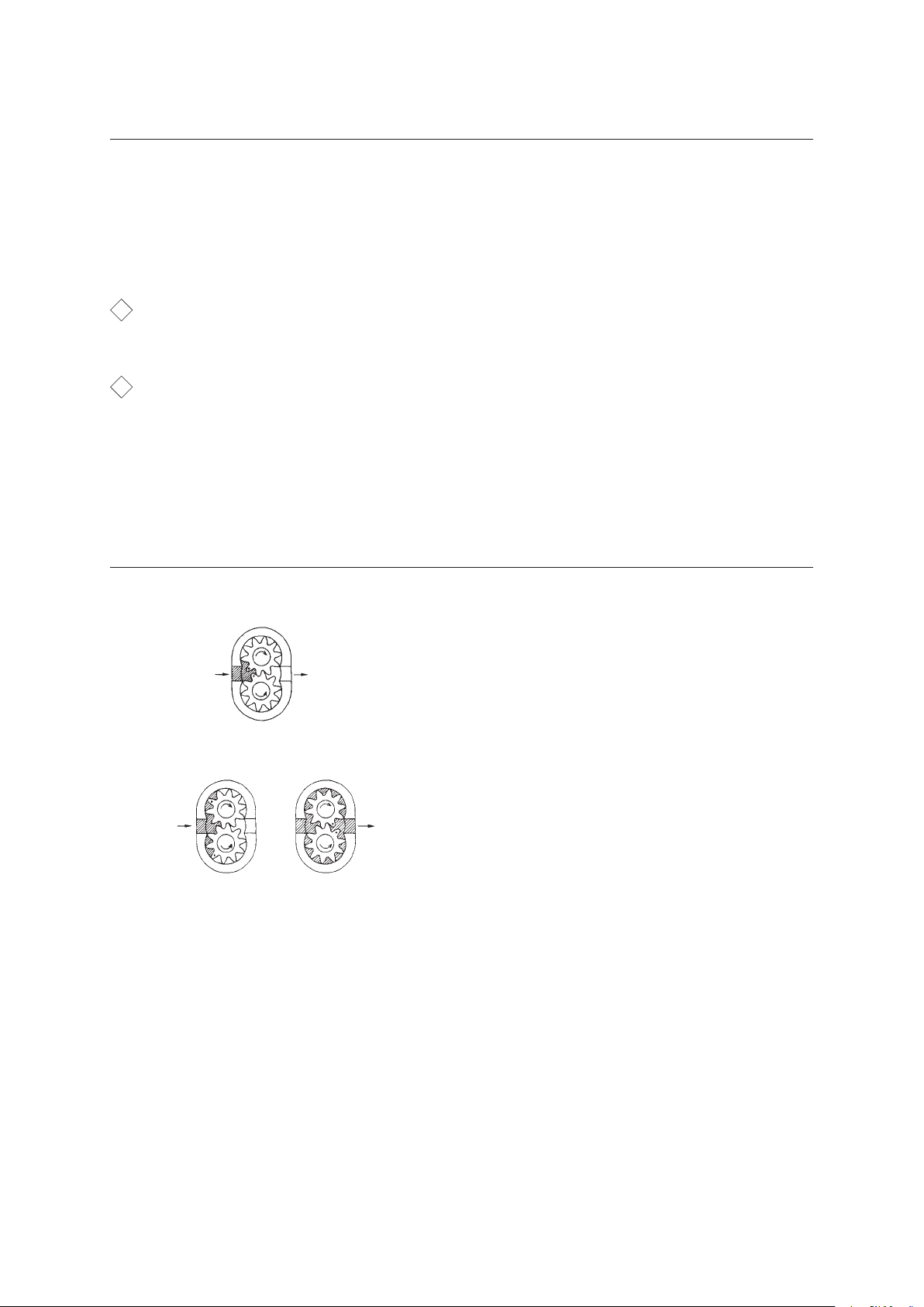
The Iwaki Magnet Gear Pump comprises a
pair of gears driven by a magnet coupling
and casing in which the gears are fitted
exactly. (Fig. A)
Liquid introduced from the IN side feeds
into the grooves between the teeth of the
gears and is transferred to the OUT side by
rotation of the gears. (Fig. B)
This liquid is forced out of the grooves
between the gear teeth by meshing of the
gears. (Fig. C)
— 4 —

PumpIdentificationCodes
③
MDG - M4 S 6 B 115 H
① ② ③ ④ ⑤
① Represents the temperature range and viscosity limit of the liquid to be
handled.
S : Tem p er a tur e ............ b e tw e en 0 an d 5 0ºC
Vis co s ity .................. b e l ow 3 0mP a·s
T : Tem p er a tur e ............ b e tw e en 0 an d 9 5 ºC
Vis co s ity .................. b e l ow 8 0mP a·s(100 W mo tor)
below 200mPa·s(150W mo tor)
② Represents the m ax imu m discha rge pressu re.
6 : 0.6MPa
③ Connection
B : 1/4NPT
④ Li ne volta ge
115 : AC115V single phase
220 : AC220 ~ 240V single phase
⑤ Non-standard specif ication code
Without code : Equipped with a 100W motor
H : Equipped with a 150W motor
— 5 —
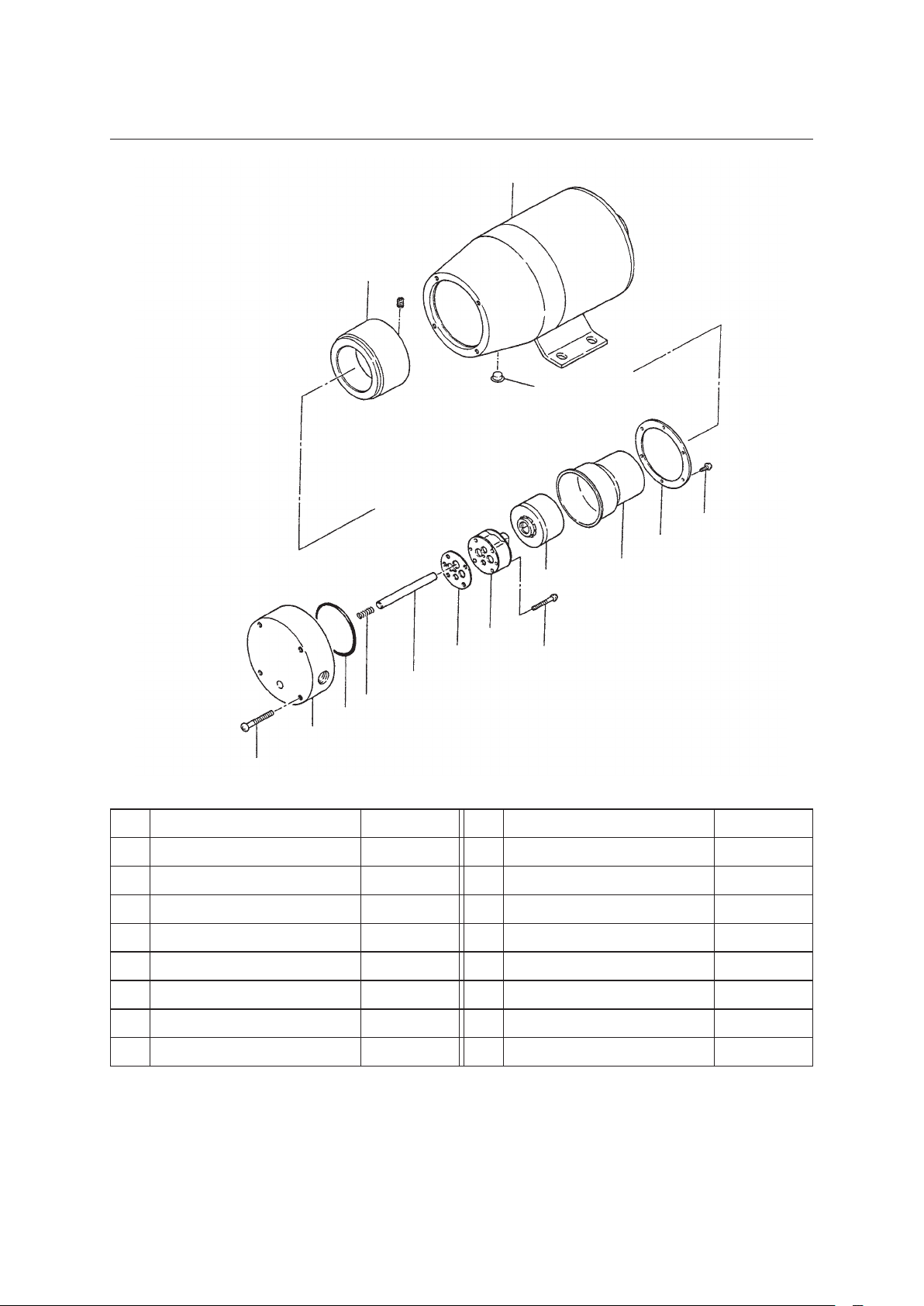
NamesofPartsandStructure
④
1
4
25
28
7
6
5
47
10
9
20
11
19
29
No. Name Number No. Name Number
1 Motor 1 19 Pump body 1
4 Driving magnet assy 1 set 20 Shaft spring 1
5 Rear casing 1 25 Cap 1
6 Magnet capsule 1 28 Screw M3×10 6
7 Mounting plate 1 29 Screw M4×35 4
9 Driving gear shaft 1 30 Screw M3×25 4
10 Gasket 1 47 Gear case unit 1 set
11 O ring 1
30
— 6 —

Precautionarymeasures
Highly viscous
⑤
1
Do not operate the pump dry.
The pump should not be operated
dry or while the suction side is
closed. This will wear out the gears
and bearings.
2
Range of liquid temperatures
The pump can be used with liquids
in the following temperature range.
The performance will change
depending on the temperature of the
liquid.
● Type S : 0 ~ 50ºC
liquid
● Type T : 0 ~ 95ºC
In case the liquid being handled is
a solvent, the gears may swell to
force the pump to stop, in the worst
case. For further information,
please contact us.
3
Liquid viscosity
Highly viscous liquid cannot be
transferred.
● Type S : up to 30mPa·s
● Type T : 80mPa·s(with a 100W
motor)
200mPa·s(with a 150W
motor)
— 7 —

4
Do not use the pump for transferring
Slurry liquid
slurry liquid or liquid which begins
to crystallize when stationary.
5
Do not splash water on the motor.
This may cause an electric leak or
burning.
6
Do not cover the motor unit tightly
with a cover, etc. Avoid operating
the pump at an ambient temperature
above 40ºC. The relative humidity
should be below 85%. Do not splash
water on the motor. It may cause an
electric leak or damage by fire.
— 8 —

Installation,PipingandWiring
⑥
Flooded suction
■
Installation
1
Choose a place which has an
ambient temperature below40°C
and a relative humidity lessthan
85%, and is convenient for
maintenance and checking. The
pump must not be installed
outdoors without suitable
protection.
2
To prevent dry running, install the
pump in a position lower than the
surface of the liquid in the tank on
Priming method
(In case the pump chamber is wet)
①There is no liquid in the suction piping
(This is not allowed for the T type).
0.3m
②There is liquid inside the suction piping.
the suction side (Flooded suction).
3
In case it is necessary to install an
S type pump in a position in which
the inlet of the pump remains
higher than the liquid surface (a
suction lift), refer to the
illustrations opposite. In this
position, the pump does not suck if
the pump chamber is not wet.
(The T type pumps do not function
on a suction lift.)
5m
— 9 —

4
For fixing the pump, use M6 small
screw. In the event floor on which
the pump is installed is resonant and
causes a loud noise, fix the pump
with rubber mountings.
■
Piping
1
In order to reduce the friction
resistance of liquid, the piping
should be as short and with as few
bends as possible.
2
The inlet and outlet joints of the
pump should be completely sealed
with sealing tape, etc. To prevent
them from sucking air. If sealing is
incomplete on the suction side, in
particular, air is sucked in and the
performance of the pump is lowered.
3
For connection, use a thick hose
which can withstand pump pressure.
Since the hose on the suction side,
particularly, tends to be crushed by
sucking force, the use of for example,
a Teflon hose is recommended. (In
the case of hot liquid, particular care
should be taken.)
■
Wiring
1
Use proper wiring connections. Wiring should be carr ied out in accordance
with the technical standa rd of electric installation and interior wir ing
regulations, referring to the opposite diagram.
2
Make sure to include a ground wire or a ground terminal i n the wi r ing.
● Rated Electric Current Value 50/60Hz
Model of Pump Rated Voltage (V) Rated Current (A)
MDG-M4[S/T]6B115 115 1.5 / 1.7
MDG-M4[S/T]6B220
220 ~ 240
MDG-M4T6B220H 1.4 / 1.5
— 10 —
0.70 / 0.84

Operation
⑦
■
NotesonOperation
1
Dry running is strictly prohibited. This will damage the inside of the pump.
2
The pump should not be operated with closed valves. If this happens, the bearing
will abnormally worn away.
3
In case liquid which solidifies or causes precipitation is handled, the pump should
be flushed clean when it is out of operation.
4
In cold weather, the pump should be kept warm so as not to be frozen.
5
When operation is restarted after having been stopped for a long time, the same
points as in starting up should be confirmed.
■
Startingup
The following items must be checked when starting up the pump.
No. Item Remarks
● Conrm piping and electrical wiring,
Conrmation of piping,
1
wiring and voltage
2 Conrmation of valves
Conf irmat ion of liquid
3
in pump
4 Starting up
referring to descriptions in piping and wiring
sections.
● Confirm that power voltage is appropriate.
● Valves on suction side and discharge side
should be fully opened.
● When S type pump is used for suction lift,
prime pump sufficiently. T ty pe pumps cannot
be used for suction lifting. Fill piping with
liquid before starting operation.
● After confirming items 1~3 above, start
operation.
● During operation, watch for items listed in
following section.
— 11 —

■
NotesonDuringOperation
The following points must be checked while the pump is in operation. If something
abnormal occurs, stop the operation immediately and take proper measures by
referring to the section ‘‘Causes of Trouble and Troubleshooting’’ (Page 16). In case
the pump still cannot be restored to normal condition, please contact your supplier.
No. Check Point Remarks
Is pump transferring
1
liquid properly?
Is there abnormal noise
2
or vibration?
Is liquid leaking or air
3
being sucked out from
joints of pump?
● Whether liquid is transferred.
● Whether suction and discharge pressures are at
normal levels.
● If pump does not function normally,
abnormal noise or vibration tends to be
generated.
● Base on which pump is mounted sometimes
becomes resonant, increasing noise. If
separation of pump from base decreases
noise, anti-vibration measure such as
anti-vibration rubber should be mounted.
● Clamp connections more tightly.
● If many air bubbles are found in discharged
liquid, air is being sucked out. Examine
piping and clamp connection more tightly.
Is temperature of pump
unit surface, motor
4
surface, etc., abnormally
high?
● Pump unit surface temperature is same as
that of liquid handled.
● Temperature of motor surface is within
about 40°C above ambient temperature.
Sometimes it is too hot to touch, but it is
normal if temperature is within this range.
— 12 —

MaintenanceandInspection
⑧
■
DailyInspection
1
Pay attention to the operating condition, referring to ‘‘Notes on Operation During
Operation’’. When any of the consumable parts reaches its replacement time or the
performance is noticeably lowered, substitute the gear case unit and the driving
gear shaft with new ones.
■
ConsumableParts
No. Part Number Raplacement Time
47
9
10 Gasket 1 at every maintenance
The above replacement periods have been estimated based on the length of time in
which the initial flow rate of clear water at normal temperature under a pressure of
0.5MPa loweres by 20%.
Gear Case
Unit
Driving
Gear
shaft
1 set
5,000 hours
1
— 13 —

DisassemblingandReassembling
⑨
Pump unit
Screw
Motor
■
DisassemblingProcedure
1
Unscrew 4 screws (29) to detach the pump unit from the motor unit.
2
Unscrew the screws (28) and remove the mounting plate (7), rear casing (5) and
magnet capsule (6) in this order.
3
Unscrew the screws (30) and remove the gear unit (47), gasket (10), drive gear
shaft (9) and shaft spring (20) in this order.
4
Remove the O ring (11).
● Put the dismantled parts in a clean place. Take care that they do not get scratched.
Particular care is required for the magnet capsule (6) which contains powerful
magnets and easily attracts iron powder, etc. Its storage should be chosen
carefully.
— 14 —

■
ReassemblingProcedure
Follow the disassembling steps in reverse, while attending to the following points.
1
Position the gasket (19) corresponding to the gear case u nit (47) as il lustr ated.
2
In at taching the gear un it (47), tighten the small screws (30) uniformly.
(Clamping torque : 1N·m)
3
If the O r i ng is flawed, replace it with a new one.
4
When the life of any of the consumable parts expires, replace the gear case
unit (47), gasket (10) a nd d r ive gear shaft (9) simultaneously.
gasket(10)
gear case unit(47)
— 15 —

CausesofTroubleandTroubleshooting
⑩
Causes
Troubles
Motor
Motor start
not increase
but rpm does
Motor stops
Liquid
cannot be
pumped up
Magnet
Too much
started.
cannot be
current is
generated.
and excess
while in
operation.
cient.
is insuf-
or pumping
coupling
comes off.
noise or
vibration.
Liquid leaks.
Contact is bad or broken somewhere in wiring.
Motor malfunctions. (Break malfunctioning of capacitor,etc.)
Thermal protector activated by overload.
Earth leakage circuit breaker activated by leak.
Dry running.
Air gets in through inlet port.
Inlet pipe is crushed.
Pressure in inlet portion is lowered to saturated vapor pressure of liquid.
Plug is out of socket.
○
○
○
○
○
○
○
○
○
○
Viscosity of liquid handled is too high.
○
○
Foreign matter sticks to gears.
Gear is damaged.
Magnet capsule hits rear casing.
Gears are locked because liquid temperature is too high.
Seal is damaged.
Bolt is loosened.
Valve is closed.
○
○
○
○
○
○
○
○
○
○
○
○
○
○
High resistance of piping.
Performance of pump lowered by decrease in liquid temperature.
○
○
○
Insert plug into socket.
Examine and repair defective part.
Countermeasure
Repair or replace.
Conrm pump is lled with liquid.
Inspect wiring and motor,and repair or replace.
Lower viscosity of liquid handled and/or discharge pressure.
Open valve.
Tighten bolt.
Replace gear.
Lower viscosity.
Substitute with crush-proof pipe.
Disassemble and remove foreign matter.
Take necessary steps to prevent air from getting in.
Lower either liquid temperature or piping resistance.
Replace seal.
Increase thickness of seal.
Alter piping to reduce resistance.
Disassemble and repair or replace parts.
— 16 —
Raise liquid temperature or change specication.

PerformanceandSizes
⑪
■
Performance
Motor Specications
Rated
Current
(V)
φ
115
φ
φ
115
φ
(A)
1.5/1.7
0.70/0.84
1.5/1.7
0.70/0.84
1.4/1.5 150/180
Rated
Output
(W)
100
Model of Pump
MDG-M4S6B115L
MDG-M4S6B220
MDG-M4T6B115L
MDG-M4T6B220
MDG-M4T6B220H
Diameter
1/4NPT
Maximum
Flow rate
(ℓ/min)
4/4.8
3.8/4.6 8.00
Maximum
Discharge
Pressure
(MPa)
0.6
Attainable
Degree of
Vacuum
kPa (abs.)
Rated
Voltage
1
5.33
1
220~240
1
1
220~240
〔Note〕 1. Above is the performance on a test of clean water at 25ºC.
(The discharge changes depending on the temperature of liquid handled.
Further i nformat ion will be supplied on request.)
2. The pumps can be used in an ambient temperature between 0 and 40ºC.
Type
2P
Induction
Motor
Capacitor
Run
Type
Weight
(kg)
7.9
8.2
3. Maximum operat ing noise is 60dB or below.
(1 m away from the front of pump, A scale)
— 17 —

■
OuterSizes
● Models MDG-M4
E
40 107 89
242
□
2-Rc1/4
OUTIN
122.5
65
120122
110
130
● Models MDG-M4
E
40 107
119
239
□H
120
2-Rc1/4
OUTIN
132.5
65
89
110
130
— 18 —

RepairService
⑫
■
Repair
In case something unusual comes to your notice while you are using the pump, stop
operation immediately and check whether anything is out of order. (Refer to the
chapter on ‘‘Causes of Trouble and Troubleshooting’’.)
1
For repair work, please contact us or the dealer with whom you placed your order.
2
Before requesting repair, peruse this instruction manual again and recheck the
product.
3
When you request repair, the following information is needed:
① Model code and manufacturing number.
② Period of use and conditions under which the product has been used.
③ Details of the problem.
In the event you return your pump, please ship it only after thoroughly washing the
inside to prevent residual liquid from flowing out in transit, which is very dangerous.
— 19 —

Australia IWAKI Pumps Australia Pty. Ltd.
Austria IWAKI EUROPE GmbH
Belgium IWAKI Belgium n.v.
China IWAKI Pumps (Shanghai ) Co., Ltd.
China
China
China
IWAKI Pumps (Guangdong) Co., Ltd.
GFTZ IWAKI Engineering & Trading (Guangzhou)
GFTZ IWAKI Engineering & T rading (Beijing )
Denmark IWAKI Nordic A/S
Finland IWAKI Suomi Oy
France IWAKI France S.A.
Germany IWAKI EUROPE GmbH
Holland
IWAKI Europe GmbH, Netherlands Branch
Hong Kong IWAKI Pumps Co., Ltd.
Indonesia
IWAKI Singapore (Indonesia Branch)
IWAKI CO.,LTD. 6-6 Kanda-Sudacho 2-chome Chiyoda-ku Tokyo 101-8558 Japan
TEL : (61)2 9899 2411 FAX : 2 9899 2421
TEL : (49)2154 92540 FAX : 2154 9254 48
TEL : (32)1367 0200 FAX : 1367 2030
TEL : (86)21 6272 7502 FAX : 21 6272 6929
TEL : (86)750 3866228 FAX : 750 3866278
TEL : (86)20 8435 0603 FAX : 20 8435 9181
TEL : (86)10 6442 7713 FAX : 10 6442 7712
TEL : (45)48 24 2345 FAX : 48 24 2346
TEL : (358)9 2745810 FAX : 9 2742715
TEL : (33)1 69 63 33 70 FAX : 1 64 49 92 73
TEL : (49)2154 9254 0 FAX : 2154 9254 48
TEL : (31)74 2420011 FAX : 2154 9254 48
TEL : (852)2 607 1168 FAX : 2 607 1000
TEL : (62)21 690 6606 FAX : 21 690 6612
TEL:(81)3 3254 2935 FAX:3 3252 8892(http://www.iwakipumps.jp)
Italy
IWAKI Europe GmbH, Italy Branch
Korea IWAKI Korea Co.,Ltd.
Malaysia IWAKIm Sdn. Bhd.
Norway IWAKI Norge AS
Singapore IWAKI Singapore Pte. Ltd.
Spain
IWAKI Europe GmbH, Spain Branch
Sweden IWAKI Sverige AB
Switzerland IP Service SA
Taiwan IWAKI Pumps Taiwan Co., Ltd.
Taiwan
IWAKI Pumps Taiwan (Hsin-chu) Co., Ltd. TEL : (886)3 573 5797 FAX : (886)3 573 5798
Thailand IWAKI (Thailand) Co.,Ltd.
U.K. IWAKI Pumps (UK) LTD.
U.S.A. IWAKI AMERICA Inc.
Vietnam IWAKI pumps Vietnam Co.,Ltd.
( )Country codes
TEL : (39)0444 37111 5 FAX : 0444 335350
TEL : (82)2 2630 4800 FAX : 2 2630 4801
TEL : (60)3 7803 8807 FAX : 3 7803 4800
TEL : (47)23 38 49 00 FAX : 23 38 49 01
TEL : (65)6316 2028 FAX : 6316 3221
TEL : (34)93 37 70 198 FAX : 93 47 40 991
TEL : (46)8 511 72900 FAX : 8 511 72922
TEL : (41)26 674 9300 FAX : 26 674 9302
TEL : (886)2 8227 6900
FAX : 2 8227 6818
TEL : (66)2 322 2471 FAX : 2 322 2477
TEL : (44)1743 231363 FAX : 1743 366507
TEL : (1)508 429 1440 FAX : 508 429 1386
TEL : (84)613 933456 FAX : 613 933399
T367-3 '15/04
 Loading...